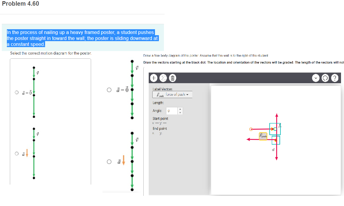
39 draw a free-body diagram of the poster. assume that the wall is to the right of the student.
For parts c) through e), assume the coefficient of kinetic friction between the box and the wall is µk = 0.30. c) [ 4 points ] Draw a free-body diagram for the box when the pole makes an angle of θ with the vertical. Describe each force present in your free-body diagram. d) [ 7 points ] Use Newton's 2nd Law to find an expression for the ... diagram for one object, there is an opposite force vector that appears in the free-body diagram for another object. An example involving two blocks on a table is shown in Fig. 4.1. If a person applies a force F to the left block, then the two free-body diagrams are shown (assume there is no friction from the table).
free body diagrams always lead to the correct answer. These question seem relatively ... If I wanted to draw a FBD in which the only ... C) blocks 2 and 3 D) blocks 3 and 4 E) blocks 1 and 2 Mechanics Lecture 6, Slide 18. In the diagram to the right: - the normal force of 4 on 3 is 40N, - the weight of 3 is 50N - the frictional force of 4 on 3 ...

Draw a free-body diagram of the poster. assume that the wall is to the right of the student.
Solution a). Free Body Diagram The box is the small blue point. In the diagram below, W is the weight of the box, N the normal force exerted by the inclined plane on the box, F a is the force applied to have the box in equilibrium and F s the force of friction opposite F a. b) The box is at rest, hence its acceleration is equal to 0, therefore the sum of all forces acting on the box is equal ... Assume that the wall is to the right of the student. In the process of nailing up a heavy framed poster, a student pushes the poster straight in toward the wall ...1 answer · 1 vote: Here, the free body diagram for the given system for a given poster is as follows: Wall N W- mg From the above diagram, F is the applied force vector, ... 1 answerDraw a free-body diagram of the poster. Assume that the wall is to the right of the student. In the process of nailing up a heavy framed poster, a student ...
Draw a free-body diagram of the poster. assume that the wall is to the right of the student.. B) Draw a free-body diagram of the poster. Assume that the wall is to the right of the student. Draw the vectors starting at the black dot. The location and orientation of the vectors will be graded. The length of the vectors will not be graded. (Correct answer is F push vector pointing right, n vector pointing left, and fk vector pointing up ... and F = 18.0 N. Draw a separate free-body diagram for each block and find (a) the acceleration of the blocks, (b) the resultant force on each block, and (c) the magnitudes of the contact forces between the blocks. 4) The assembly in the Right Figure is used to calculate the acceleration of a given system. An observer on the To draw a free body diagram, start by sketching a simple representation of the body you want to make the diagram of, like a square to represent a box. Next, draw arrows on the shape that show the forces acting on the object. For example, draw a downward arrow to signify the weight of the object, since gravity pulls the object down. Then, draw lines for the other forces, such as a sideways ... The beam is uniform, weighs 200 N, and is 6.00 m long; the goodies weigh 80.0 N. (a) Draw a free-body diagram of the beam. (b) When the bear is at x = 1.00 m, find the tension in the wire and the components of the reaction force at the hinge.
The coefficient of kinetic friction between the sled and the snow, as well as that between the sled and the penguin, is 0.20. (a) Draw a free-body diagram for the penguin and one for the sled, and identify the reaction force for each force you include. Determine (b) the tension in the cord and (c) the acceleration of the sled. Figure P4.64. 65. Draw A Free-body Diagram Of The Poster. Assume That The Wall Is To The Right Of The Student. This problem has been solved! See the answer. In the process of nailing up a heavy framed poster, a student pushes the poster straight in toward the wall; the poster is sliding downward at a constant speed. Draw a free-body diagram of the poster. Assume that the wall is to the right of the student ... A free-body diagram is a diagram that depicts the type and the direction of all the forces acting upon an object. The following descriptions and their accompanying free-body diagrams show the forces acting upon an object. For each case, indicate which force(s) are doing work upon the object. Then calculate the work done by these forces. Free-Body. Diagram. Forces Doing Work. on the Object ... Again assume the wall is frictionless. A free-body diagram is shown in Fig. 9-63. We know at the point of slipping that F Gx (See diagram above) is just equal to the friction force, where the normal force is F Gy (The upward force exerted by the ground on the ladder - see diagram above.) So, applying the formula for friction:
The wall of the ride is the source of the centripetal force. Part B Answer: Centripetal force = (mv^2/r) Centripetal force = ((55.0 kg)*(10.0 m/s)^2)/3.30 m Centripetal force = 1670 N Part C Answer: In order to help me solve this, I drew a free body diagram and realized that the normal force was not vertical, but horizontal. Therefore, it ... Draw a free-body diagram of the poster. Assume that the wall is to the right of the student. In the process of nailing up a heavy framed poster, a student ...1 answer · 0 votes: 18 no NAI 1 XANB * This pis the correct FBD. Petose the change is in the direction of NA The correct direction should be downward. Because Consider Moments ... To set up the equilibrium conditions, we draw a free-body diagram and choose the pivot point at the upper hinge, as shown in panel (b) of (Figure). Finally, we solve the equations for the unknown force components and find the forces. Figure 12.17 (a) Geometry and (b) free-body diagram for the door. (a) Draw a free body diagram for the beam (b) When the bear is at x = 1 m, find the tension in the wire and the components of the force exerted by the wall on the left end of the beam. t cw = t ccw if it balanced. 700*1 + 200*3 + 80*6 = T sin60 ° * 6
Draw a free body diagram of the poster Assume that the wall is to the right of the student Draw the vectors starting at the black dot. Question: Problem 4.60 In the process of nailing up a heavy framed poster, a student pushes the poster straight in toward the wall; the poster is sliding downward at a constant speed. Select the correct motion ...
A free-body diagram of the situation is depicted at right. ... A picture hangs on the wall suspended by two strings, as shown in the figure . The tension in string 1 is 1.7 N. 31. Picture the Problem: The free-body diagram for the contact point between the two strings is depicted at right. Strategy: The horizontal components of the string ...
2. The object in the diagram below is on a fixed frictionless axle. It has a moment of inertia of I = 50 kgm2. The forces acting on the object are F1 = 100 N, F2 = 200 N, and F3 = 250 N acting at different radii R1 = 60 cm, R2 = 42 cm, and R3 = 28 cm. Find the angular acceleration of the object.

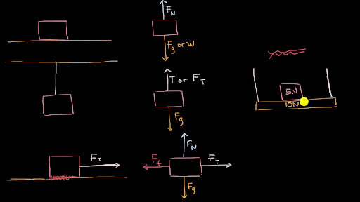
A free body diagram models the forces acting on an object. The object or 'body' is usually shown as a box or a dot. The forces are shown as thin arrows pointing away from the centre of the box or ...

3. Draw a free-body diagram for each object identified in step 2. a. Assuming that the object can be modeled as a particle, you can represent it by a large dot. Do not include other objects (such as a surface the object may be rest-ing on or a rope pulling on it) in your free-body diagram. b.
A student draws the flawed free-body diagram shown in Figure P4.52 to represent the forces acting on a golf ball that is traveling upward and to the right a very short time after being hit off the tee. Air resistance is assumed to be relevant. Identify the errors in the diagram, then draw a correct free-body diagram for this situation.
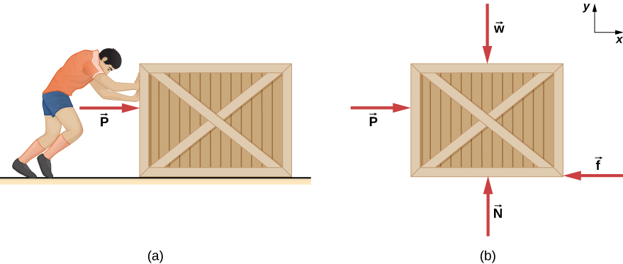
Draw a free-body diagram of the poster. Assume that the wall is to the right of the student. In the process of nailing up a heavy framed poster, a student pushes the poster straight in toward the wall; the poster is sliding downward at a constant speed.

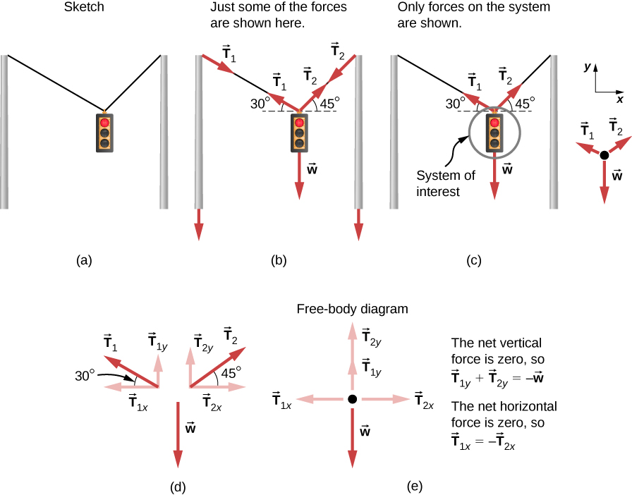
Some problems contain multiple force vectors acting in different directions on an object. Be sure to draw diagrams, resolve all force vectors into horizontal and vertical components, and draw a free-body diagram. Always analyze the direction in which an object accelerates so that you can determine whether F net = m a Fnet=ma or F net = 0. Fnet=0.
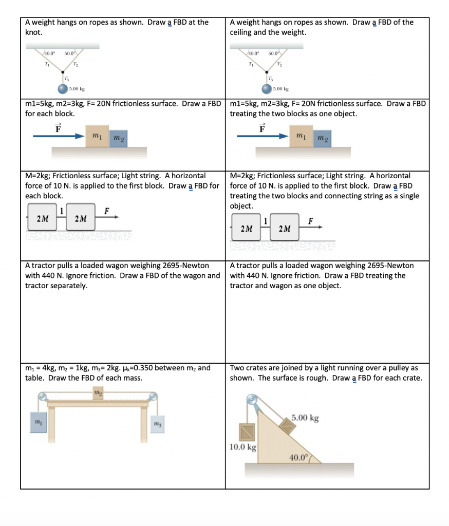
b) Draw a free-body diagram (FBD) of all forces acting on block 2 (M 2). Use this to determine the magnitude and direction of the friction force f k,2, acting on block 2. Calculate the coefficient of kinetic friction, µ k, between surfaces of block 2 and incline. In diagram below the forces and acceleration are dented by the solid black arrows.
The mass of the box is 0.80 kg, and the spring has a spring constant of 59 N/m. The coefficient of static friction between the box and the table on which it rests is μs = 0.74. (a) Draw the free-body diagram showing the forces that act on the box.

Draw three clear free-body diagrams for the three masses. Do not draw in all the forces on a single diagram. That gets far too confusing! For the 4.0 kg mass and its motion, take the downward direction to be positive. F net = w - T l = m a m g - T l = m a (4.0 kg) (9.8 m/s 2) - T l = (4.0 kg) a

To better understand how to draw free-body diagrams using the 3 steps, let's go through several examples. Example 1. A box is pushed up an incline with friction which makes an angle of 20 ° with the horizontal. Let's draw the free-body diagram of the box. The first step is to sketch what is happening: 20 ° Push Friction. The next step is to look at the sketch, and enumerate all the forces to ...
It is fixed to the wall at C. Solution The problem can be solved by considering segment AB, which does not involve the support reactions at C. Free-Body Diagram.The x, y, z axes are established at B and the free-body diagram of segment AB is shown in Fig. 1-8b.The resultant force and moment components at the section are assumed to act in

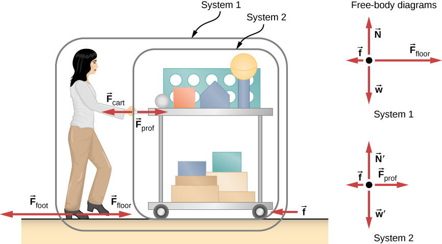
Figure 5.32 (a) The free-body diagram for isolated object A. (b) The free-body diagram for isolated object B. Comparing the two drawings, we see that friction acts in the opposite direction in the two figures. Because object A experiences a force that tends to pull it to the right, friction must act to the left. Because object B experiences a component of its weight that pulls it to the left ...

Draw a free-body diagram of the elevator. Tension goes straight up the y axis. Weight goes straight down with a slightly smaller arrow. Net force arrow goes up to the right under the x axis. small arrow. ... A 3.2 kg flagpole extends from a wall at an angle of 25° from the horizontal. Its center of gravity is 1.6 m from the point where the ...
Draw a free-body diagram of the poster. Assume that the wall is to the right of the student. In the process of nailing up a heavy framed poster, a student ...

Draw a free-body diagram of the poster. Assume that the wall is to the right of the student. In the process of nailing up a heavy framed poster, a student ...1 answer · 0 votes: Fo G1

Draw a picture of the situation. Show the object—the system—and everything in the environment that touches the system. Ropes, springs, and surfaces are all parts of the environment. Consider a system at the time. Locate every point where the environment exerts contact forces on the object.

5.7 Drawing Free-Body Diagrams. To draw a free-body diagram, we draw the object of interest, draw all forces acting on that object, and resolve all force vectors into x- and y-components. We must draw a separate free-body diagram for each object in the problem.

An example of a free-body diagram is shown at the right. T he free-body diagram above depicts four forces acting upon the object. Objects do not necessarily always have four forces acting upon them. There will be cases in which the number of forces depicted by a free-body diagram will be one, two, or three. There is no hard and fast rule about the number of forces that must be drawn in a free ...
1 answerDraw a free-body diagram of the poster. Assume that the wall is to the right of the student. In the process of nailing up a heavy framed poster, a student ...
Assume that the wall is to the right of the student. In the process of nailing up a heavy framed poster, a student pushes the poster straight in toward the wall ...1 answer · 1 vote: Here, the free body diagram for the given system for a given poster is as follows: Wall N W- mg From the above diagram, F is the applied force vector, ...
Solution a). Free Body Diagram The box is the small blue point. In the diagram below, W is the weight of the box, N the normal force exerted by the inclined plane on the box, F a is the force applied to have the box in equilibrium and F s the force of friction opposite F a. b) The box is at rest, hence its acceleration is equal to 0, therefore the sum of all forces acting on the box is equal ...


0 Response to "39 draw a free-body diagram of the poster. assume that the wall is to the right of the student."
Post a Comment