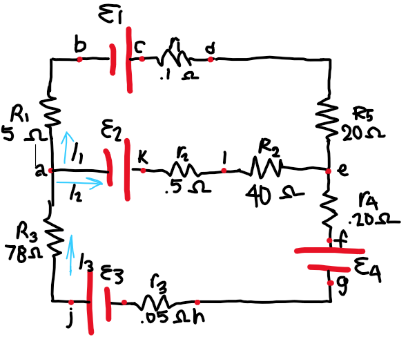
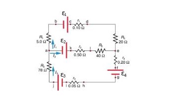
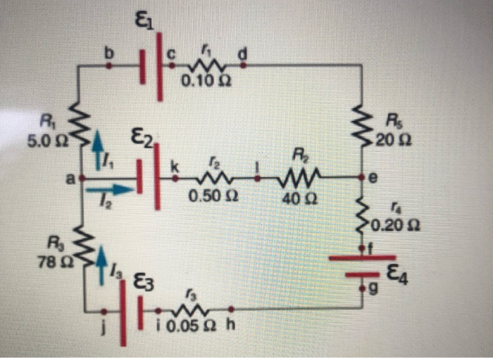
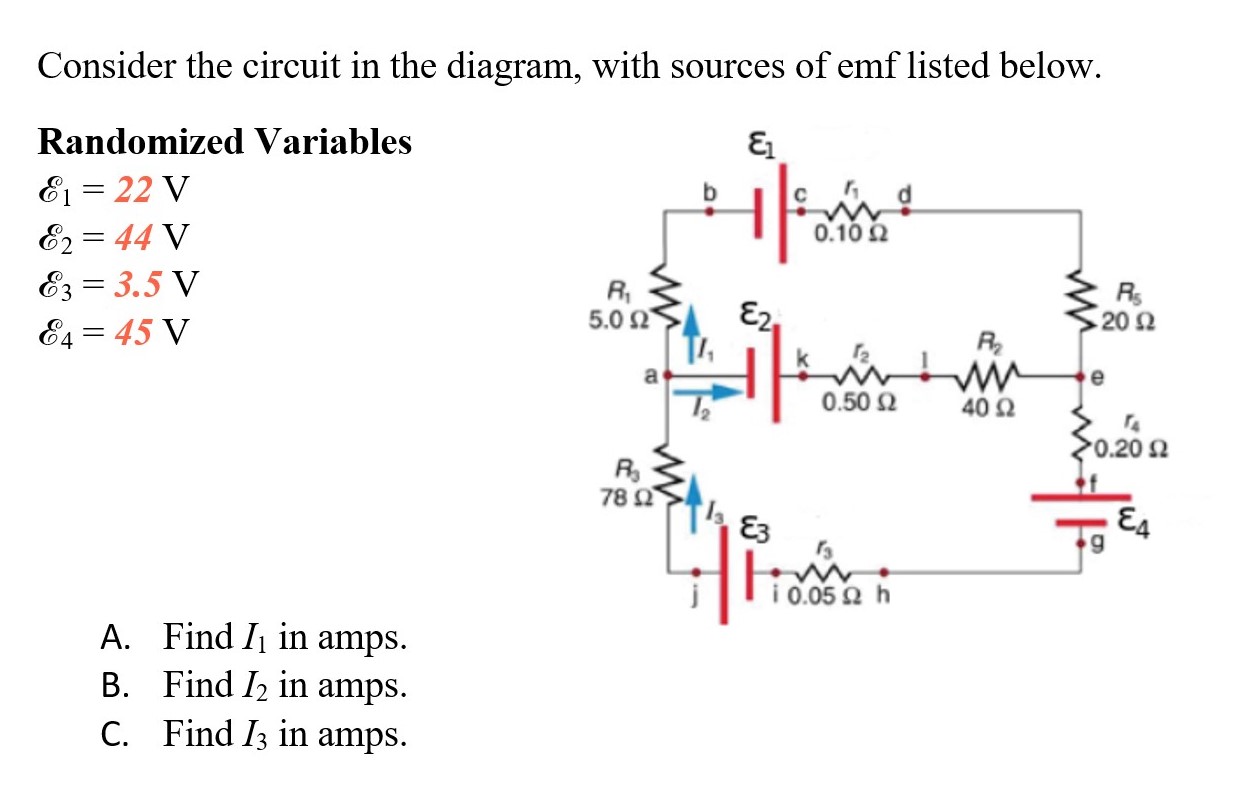
39 consider the circuit in the diagram, with sources of emf listed below.
(b) The circuit diagram of the two batteries and the load resistor, with each battery modeled as an idealized emf source and an internal resistance. When voltage sources are in series, their internal resistances can be added together and their emfs can be added together to get the total values. Answer to: Consider the circuit in the diagram with in the diagram with sources of emf listed below Randomized variable E 1 = 25 v E 2 = 46v ...
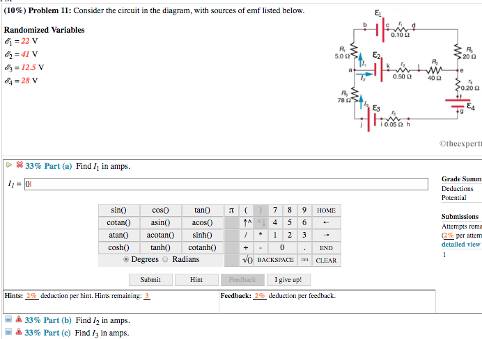
Question: (9%) Problem 6: Consider the circuit in the diagram, with sources of emf listed below Randomized Variables 81-29 V 0.1 R, 20Ω 83-6.5 V 84-43 V 0.50 Ω 40Ω 020 Ω 78 Ctheexpertta.c Li 33% Part (a) Find 11 in amps. 33% Part (b) Find 12 in amps. 33% Part (c) Find 13 in amps.

Consider the circuit in the diagram, with sources of emf listed below.
Solution for (6%) Problem 16: Consider the circuit in the diagram, with sources of emf listed below. Randomized Variables 0.10 2 E1 = 22 V E2 = 44 V Ez = 3.5 V… Consider the battery in the figure. The voltage of the battery is defined as the difference in electric potential between its positive and negative terminals: i.e., the points and , respectively.As we move from to , the electric potential increases by volts as we cross the emf, but then decreases by volts as we cross the internal resistor. The voltage drop across the resistor follows from Ohm ... Consider the circuit in the diagram with in the diagram with sources of emf listed below randomized variable e 1 25 v e 2 46v. Find the voltage drop across the 10 ohm resistor. A the number of state variables required to describe the dynamic circuit behavior b list a set of state variables that could be used to determine circuit behavior c ...
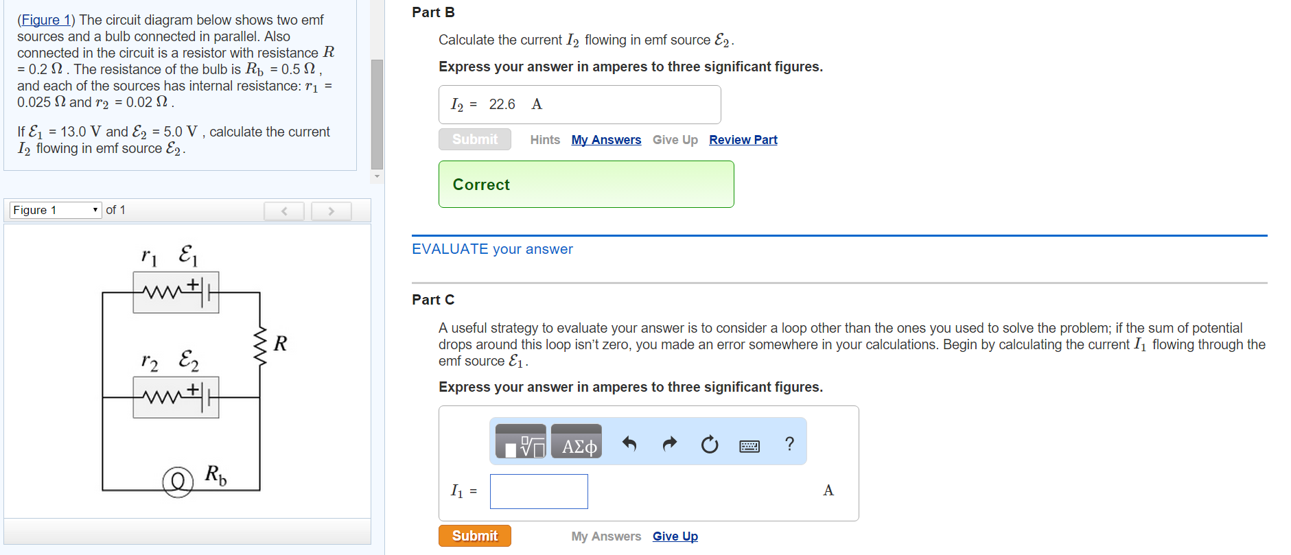
Consider the circuit in the diagram, with sources of emf listed below.. Consider the Circuit In the Diagram with sources Of Emf Listed Below. training ueeneee104a solve problems in d c australian government department of education and training training gov au magnetic shielding materials emf safety superstore circuit breaker shield decorative magnetic shielding a circuit breaker box or fuse box in the bedroom living room kitchen or other living space can The initial velocity of the ball is 20 m/s Ð 408 ABOVE HORIZONTAL. How far above or below its original level will the ball strike the opposite wall? Fig. 2-8 We have vix 20 m=s cos 408 15:3 m=s viy 20 m=s sin 408 12:9 m=s Consider ®rst the horizontal motion. Consider the circuit in the diagram, with sources of emf listed below. Randomized Variables Ac„° 1 = 29 V Ac„° 2 = 41 V Ac„° 3 = 4.5 V Ac„° 4 = 35 V Part (a) Find I 1 in amps. Part (b) Find I 2 in amps. Part (c) Find I 3 in amps. The circuit diagram below shows two emf sources and a bulb connected in parallel. Also connected in the circuit is a resistor with resistance R = 0.2 . The resistance of the bulb is Rb = 0.5 , and each of the sources has internal resistance: r1 = 0.025? and r2 = 0.02 ? .
(b) The circuit diagram shows the shows battery as an emf source and an internal resistor. The two emf sources have identical emfs (each labeled by ) connected in parallel that produce the same emf. Consider the Kirchhoff analysis of the circuit in (Figure) (b). Problem: Consider the circuit in the diagram, with sources of emf listed below.Randomized Variablesℰ1 = 21 Vℰ2 = 49 Vℰ3 = 9.5 Vℰ4 = 39 Va) Find I1 in amps.B) Find I2 in amps.C) Find I3 in amps. This photo about: Consider the Circuit In the Diagram with sources Of Emf Listed Below, entitled as Electrical Engineering Archive November 01 2014 Consider The Circuit In The Diagram With Sources Of Emf Listed Below - also describes Electrical Engineering Archive November 01 2014 and labeled as: ], with resolution 1958px x 1457px Consider the circuit in the diagram with sources of emf listed below. The resistance of the bulb is rb 05 ohms and each of the sources has internal resistance. The circuit diagram below shows two emf sources and a bulb connected in parallel. Randomized variables varepsilon1 29 v varepsilon2 41 v. D 33 part c find 3 in amps.
Academia.edu is a platform for academics to share research papers. Problem 6: Consider the circuit in the diagram, with sources of emf listed below Randomized Variables EI-25 V & 49 V 0.102 5.0 Ω 20Ω R2 0.50 Ω 40Ω 4 31 V 0.20 Ω Ra 9 ¡0.05 Ω h Otheexpertta.com Part (a) Find /1 in amps. . tan( cos(0) cotan0asin) acos(0 sin() 4 5 6 *1 23 0 atan()acotan( sinh() cosh)tanh) cotanh O Degrees O Radians BACKSPACE CLEA Submit Hint I give up! Consider the circuit shown in the diagram below where. Consider the circuit in the diagram with sources of emf listed below. The sum of all potential changes around a closed loop is zero junction rule. Homework statement consider the circuit shown in the diagram below for r1 5 ω r2 8 ω r3 8 ω r4 8 ω and v0 80 v. Find i2 in amps. Find i3 in ... A K.Sawhney-A course in Electrical and Electronic Measurements and Instrumentation
Circuits Rs R Ig Is I R Rs A Chapter 27 R V R E I Ppt Download
Consider the circuit in the diagram with sources of emf listed below. Consider the circuit in the diagram with sources of emf listed below. Show more 1 consider the circuit in the diagram below in which r 10 ω. With resolution 1584px x 1379px. Ohm S Law Electric Circuits Siyavula Solved 10 Problem 11 Consider The Circuit In The Diag

State Of Charge Estimators Considering Temperature Effect Hysteresis Potential And Thermal Evolution For Lifepo4 Batteries Xie 2018 International Journal Of Energy Research Wiley Online Library
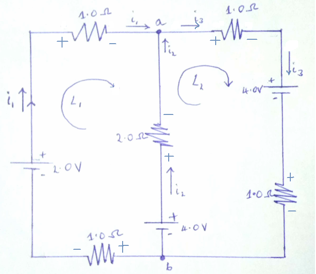
2. The source that maintains the constant currentin a closed circuit is called a source of "emf." a) One can think of such a source as a "charge pump" =⇒ forces electronstomove in adirection oppositetheE-field, hence current, inside a source. b) The emf, E, of a source is the work done per unit charge =⇒ measured in volts. c) A ...
Solved The Circuit Diagram Below Shows Two Emf Sources And A Chegg Com
Consider the circuit in the diagram, with sources of emf listed below: E1= 27V E2=41V E3=7.5V E4=39V Find I1, I2, I3 in amps Ο.10 8, 5.0 Ω 20 Ω 0.50 Ω 20 Ω 78 Ω 10.05 Ω h Review A circuit contains a source of constant voltage V and two resistors connected in parallel,...
Sshi Based Zero Quiescent Power Control For The Electromagnetic Energy Harvester
(7%) Problem 3: Consider the circuit in the diagram, with sources of emf listed below, ca 0.10 0 Randomized Variables E = 22 V 5.0 20 0 EL = 42 V [T, KyHe 1 0.50 40 a . E3 = 6.5 V a E4 = 38 v 0.20 0 78 a ji 05 a h Otheexpertta.com A 33% Part (a) Find I1 in amps. a 33% Part (b) Find 12 in amps.
Electronics Free Full Text Electromagnetic Field Based Wpt Technologies For Uavs A Comprehensive Survey Html
The in the with of emf listed randomized variables 6 29 v 502 47 85 45 78 q a. Consider the circuit in the diagram with sources of emf listed below. I know the top one is stronger so the current is traveling in a counter clockwise manner but dont know the technique when there are two emf sources for solving the magnitude of the current.
Wright Edu
a. In a space below draw a diagram showing all the elements connected In one electrical circuit that can provide the maximum rate of heat produced. Use two meters in your circuit. they will help to measure the heat rate The battery has an emf of 12 V and an internal resistance of 0.5 Q and each heating coil has a resistance of 17.3 Q
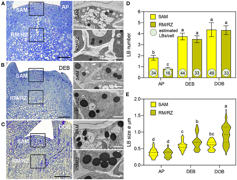
Frontiers Lipid Body Dynamics In Shoot Meristems Production Enlargement And Putative Organellar Interactions And Plasmodesmal Targeting Plant Science
design a circuit so that the device will operate properly when the circuit is connected across a battery of emf 24 volts and negligible internal resistance. Within the dashed-line box in the diagram to the right, draw the circuit using the symbol for the device and the appropriate symbol for each 3-ohm resistor.

The Circuit Diagram Below Shows Two Emf Sources And A Bulb Connected In Parallel Also Connected Homeworklib
8/9/2017 The Expert TA | Human-like Grading, Automated! 6/17 Problem 5: Consider the circuit in the diagram, with sources of emf listed below. Randomized Variables 1 = 26 2 = 49 3 = 2.5 4 = 25 Part (a) Find I 1 in amps. V V V V I 1 = 4
Andritz Com
Enter the email address you signed up with and we'll email you a reset link.

Wireless Power Transfer And Telemetry For Implantable Bioelectronics Yoo 2021 Advanced Healthcare Materials Wiley Online Library
Consider the circuit shown below. The terminal voltage of the battery is (a) Find the equivalent resistance of the circuit. (b) Find the current through each resistor. (c) Find the potential drop across each resistor. (d) Find the power dissipated by each resistor. (e) Find the power supplied by the battery.

Regulation Of Stem Cell Fate Using Nanostructure Mediated Physical Signals Chemical Society Reviews Rsc Publishing Doi 10 1039 D1cs00572c
Electrical and Electronic Principles and Technology 3rd ed by John Bird.pdf
Repository Its Ac Id
Questions 14-15 refer to the following diagram that shows part of a closed electrical circuit. 14. The electrical resistance of the part of the circuit shown between point X and point Y is (A) 4/3 (B ) 2 (C) 4 (D) 6 15. When there is a steady current in the circuit, the amount of charge passing a point per unit of time is

Theoretical And Experimental Investigations On Optimization Of The Received Power Of A Monopole Antenna Iopscience
Jun 12, 2018 · Consider the circuit in the diagram with sources of emf listed below. The four resistors have resistances of and calculate the rate at which heat is being generated in the resistor r4. The source that maintains the constant currentin a closed circuit is called a source of emf a one can think of such a source as a charge pump forces electronstomove in adirection oppositethee field hence current inside a source. Consider the circuit in the diagram with sources of emf listed below.
Solved Consider The Circuit In The Diagram With Sources Of Chegg Com
Apr 30, 2018 · The circuit diagram below shows two emf sources and a bulb connected in parallel. Randomized variables ac 1 29 v ac 2 41 v ac 3 45 v ac 4 35 v. Consider the two loads in the circuit below load brushless dc bldc motor with arduino part 2 circuit the circuit diagram below is a concept that should work with any microprocessor or a specialized driver ic that is able to produce the correct image for find the values of i and v for the circuits shown in the figure.
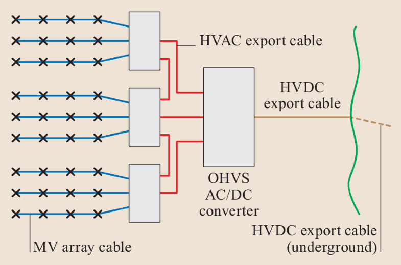
Underground Cables Springerlink
Consider the circuit in the diagram, with sources of emf listed below. Randomized variables: \Epsilon_1 = 22 V, \Epsilon_2 = 49V, \Epsilon_3=7.5V, \Epsilon_4 = 45 V. a) Find I_1 in amps, b) Find I ...
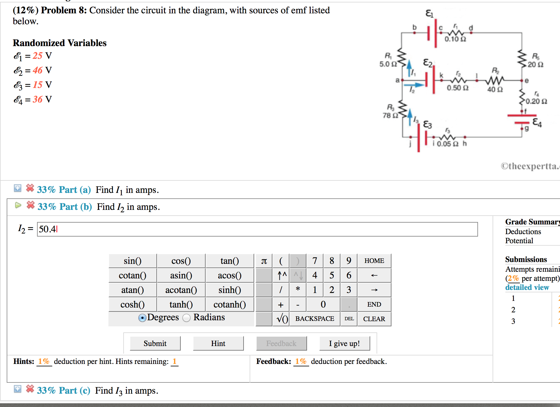
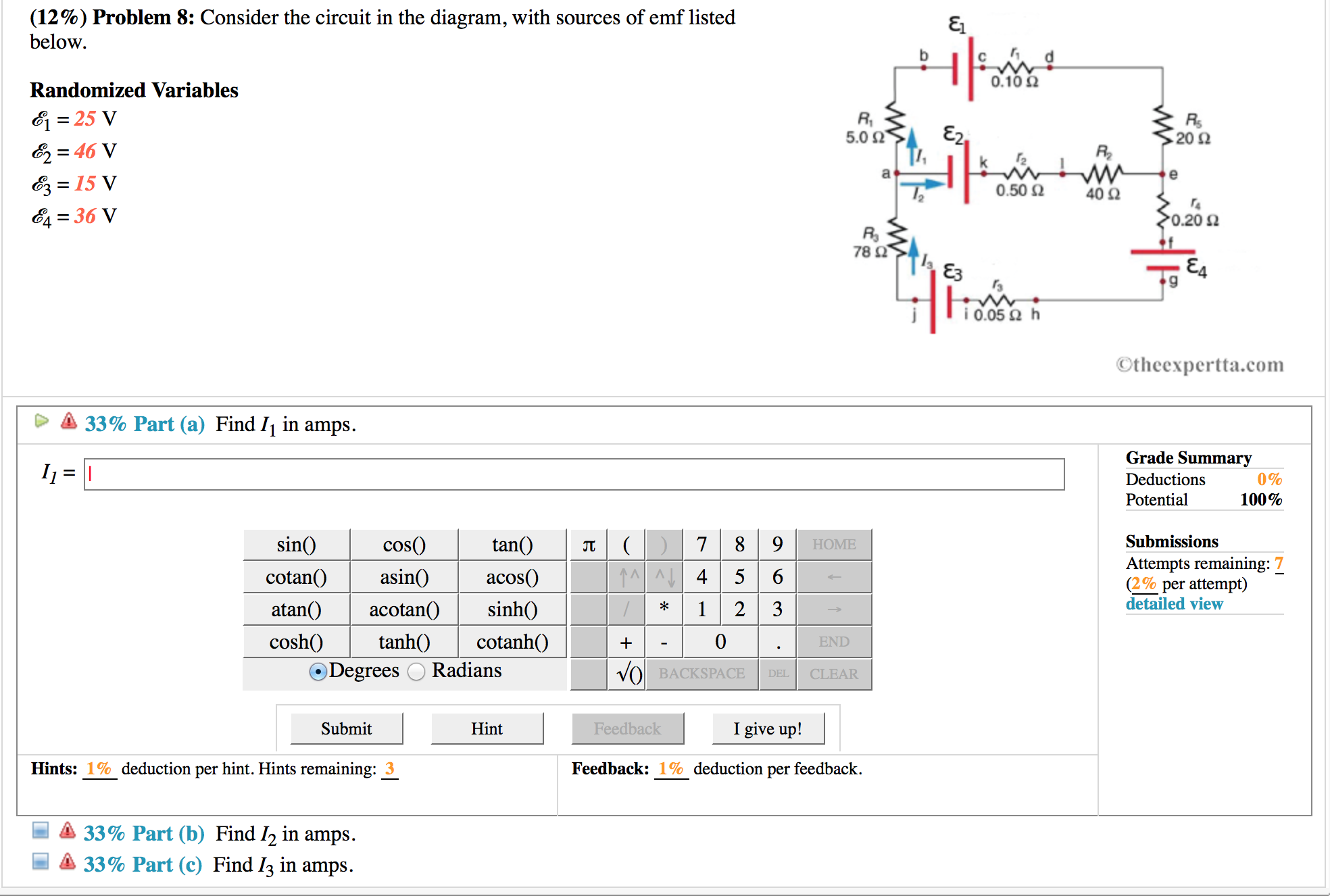
Solved 12 Problem 8 Consider The Circuit In The Diagram Chegg Com
Part b find i 2 in amps. Consider the circuit in the diagram with sources of emf listed below. Consider the circuit in the diagram with in the diagram with sources of emf listed below randomized variable e 1 25 v e 2 46v. Randomized variables ℰ1 29 v ℰ2 41 v ℰ3 95 v ℰ4 31 v 33 part a find i1 in amps.
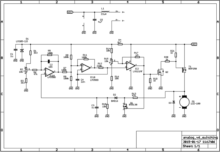
Ab 026 Sensorless Speed Stabiliser For A Dc Motor Precision Microdrives
Consider the circuit in the diagram with in the diagram with sources of emf listed below randomized variable e 1 25 v e 2 46v. Find the voltage drop across the 10 ohm resistor. A the number of state variables required to describe the dynamic circuit behavior b list a set of state variables that could be used to determine circuit behavior c ...
Consider The Circuit In The Diagram With In The Diagram With Sources Of Emf Listed Below Randomized Variable E 1 25 V E 2 46v E 3 15v E
Consider the battery in the figure. The voltage of the battery is defined as the difference in electric potential between its positive and negative terminals: i.e., the points and , respectively.As we move from to , the electric potential increases by volts as we cross the emf, but then decreases by volts as we cross the internal resistor. The voltage drop across the resistor follows from Ohm ...
Sensitivity To Electricity Temporal Changes In Austria Bmc Public Health Full Text
Solution for (6%) Problem 16: Consider the circuit in the diagram, with sources of emf listed below. Randomized Variables 0.10 2 E1 = 22 V E2 = 44 V Ez = 3.5 V…
Wireless On Demand Drug Delivery Nature Electronics
Solved Consider The Circuit In The Diagram With Sources Of Chegg Com

10 Problem 10 Consider The Circuit In The Diagram With Sources Of Emf Listed Below 5 023 E2 Randomized Variables 28 V E2 43 V Ez 11 V E 41 V 02 Me 400 78 22 Tea W 10 050 H
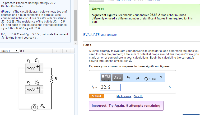
Solved To Practice Problem Solving Strategy 26 2 Kirchhoffs Chegg Com

Keithley Low Level Measurements Handbook 7th Edition Tektronix

Consider The Circuit In The Diagram With Sources Of Emf Listed Below Randomized Variables Epsilon 1 22 V Epsilon 2 49v Epsilon 3 7 5v Epsilon 4 45 V A Find I 1 In Amps B

Keithley Low Level Measurements Handbook 7th Edition Tektronix
Infineon Com

Consider The Circuit In The Diagram With Sources Of Emf Listed Below Randomized Variables Varepsilon 1 29 V Varepsilon 2 41 V Varepsilon 3 4 5 V Varepsilon 4 35 V Study Com

Solved 7 Problem 5 Consider The Circuit In The Diagram Chegg Com
The Circuit Diagram Below Shows Two Emf So Clutch Prep
Solved 10 Problem 11 Consider The Circuit In The Chegg Com
Solved Consider The Circuit In The Diagram With Sources Of Chegg Com

Sshi Based Zero Quiescent Power Control For The Electromagnetic Energy Harvester
Erepository Uwks Ac Id
Answered Consider The Circuit In The Diagram Bartleby

Consider The Circuit In The Diagram With Sources Of Emf Listed Below Randomized Variables Varepsilon 1 29 V Varepsilon 2 41 V Varepsilon 3 4 5 V Varepsilon 4 35 V Study Com
Teknologielektromedismandalawaluya Ac Id
Sustainability Free Full Text A Review On Battery Modelling Techniques Html

Imaging Nodal Knots In Momentum Space Through Topolectrical Circuits Nature Communications
0 Response to "39 consider the circuit in the diagram, with sources of emf listed below."
Post a Comment