36 truss free body diagram
Draw a Free Body Diagram (FBD) of the entire truss cut loose from its supports and find the support reactions using the equations of equilibrium (we will see that for some truss structures this step is not always necessary); 2. Draw a FBD of a truss joint that has no more than two unknowns and use the two equations of equilibrium to find the two unknown truss member forces; 3. Draw a FBD of a ... A truss is one of the major types of engineering structures which provides a practical and economical solution for many engineering constructions, especially in the design of bridges and buildings that demand large spans. ... joint's free body diagram to be in tension
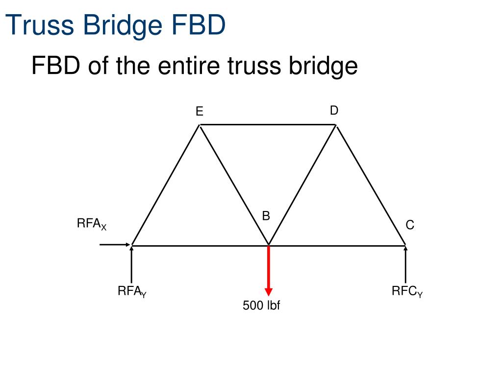
The free-body diagram of the entire truss indicates that the forces at the end supports are identical to what they were for the case of the beam. Important points about the forces in the members … which are pushing or pulling on each of the ...

Truss free body diagram
1. Draw a free-body diagram of the entire structure and determine the reactions (if r = 3). 2. Draw free-body diagrams for all members (assume tensile forces in all members) and all joints. 3. Set up the equilibrium equations for each joint and solve them one joint at a time, begin with those that have at most two unknowns. 4. Fig.1: Free Body Diagram for Truss. Please observe in the above picture, FBD of the whole truss is drawn so the unnecessary member details have not been shown. Also observe the actual reactions at P and Q has been replaced by reaction forces in the FBD. Typically in plane truss, joint at P is of hinge joint type and at Q is of roller (sliding ... Free Body Diagram Questions and Answers. Get help with your Free body diagram homework. Access the answers to hundreds of Free body diagram questions that are explained in a way that's easy for ...
Truss free body diagram. In a truss, it is assumed that the forces along the elements converge at the nodes of the structure. This fact allows us to use a free body diagram to find the acting forces values. By definition, a free body diagram (FBD) is a representation of an object with all the forces that act on it. No examples are done in this video. This really shows you what method of joints and method of sections actually are. The free-body diagram of any joint is a concurrent force system in which the summation of moment will be of no help. Recall that only two equilibrium equations can be written $\Sigma F_x = 0$ and $\Sigma F_y = 0$ This means that to solve completely for the forces acting on a joint, we must select a joint with no more than two unknown forces involved. This can be started by selecting a joint ... In this activity you will calculate reaction and member forces for the truss system illustrated below. It is essential to follow each step within the procedure to ensure proper calculations and free body diagrams. Calculate External Reaction Forcesx and y Reaction Force at Pin A and y Reaction Force at Roller C
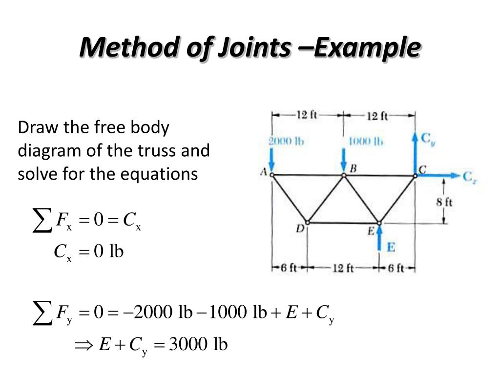
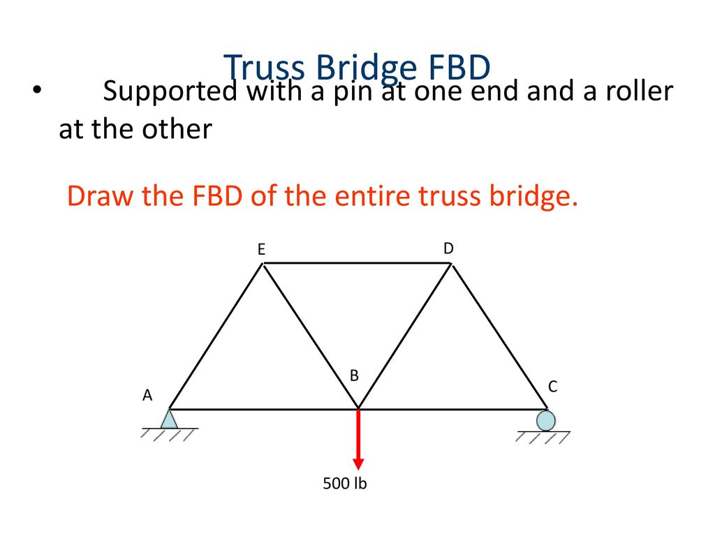
Calculate the reactions at the supports of Frame and Truss - statically determinate and statically indeterminate, automatically calculate bending moment and shear force of Frame and Truss ... To get the numerical values of the diagrams and the detailed text of the calculation, you need to Get an Access Code (detailed report example) Draw the free-body diagram for the truss. A is a pin and B is a rocker. (Part A) Draw the vectors starting at the black dots. The location and orientation of the vectors will be graded. The length of the vectors will not be graded. Part B. Draw the free-body diagram for the beam. A is a pin. Draw the vectors starting at the black dots. • Based on a free-body diagram of the entire truss, solve the 3 equilibrium equations for the reactions at E and C. • Joint A is subjected to only two unknown member forces. Determine these from the joint equilibrium requirements. • In succession, determine unknown member forces at joints D, B, and E from joint equilibrium requirements. • All member forces and support reactions are ... Truss - Example Problem. Draw the free-body diagram. The summation of forces and moment about H result in ()()()()() xHx Hx yHyI HI I Hy. 0 3 kips 3 kips 3 kips 3 kips
Trusses: Equilibrium, free body diagrams and method of joints forces for the truss i. Method of Joints ii. Method of Sections iii. Method of Force Resolution MEMBER FORCES • Suitable to be used to determine all the member forces in the truss • In this method, every joint will be analysed by drawing the Free Body Diagram, limiting the unknown values to TWO only. The objective of truss analysis is to determine the reactions and member forces. The methods used for carrying out the analysis with the equations of equilibrium and by considering only parts of the structure through analyzing its free body diagram to solve the unknowns. The method of sections: This method uses free-body-diagrams of sections of the truss to obtain unknown forces.For example, if one needs only to find the force in BC, it is possible to do this by only writing two equations. First, draw the free body diagram of the full truss and solve for the reaction at A by taking moments about D.Next draw the free body diagram of the section shown and take ...
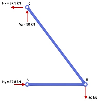
Two Bar Truss With Load
After drawing the free body diagram, we will check the given truss for determinacy. We will have to check the given truss with the equation as mentioned below to secure the information whether the given truss problem could be solved by using the principle of equilibrium or equations of static equilibrium or not.
Ppt Method Of Joints Example Powerpoint Presentation Free Download Id 3027153
The most elementary 3D space truss structure is the tetrahedron. The members are connected with ball-and -socket joints. Simple space trusses can be obtained by adding 3 elements at a time to 3 existing joints and joining all the new members at a point. ... of the machine as a free -body. ...

Truss Geometry And Free Body Diagram Download Scientific Diagram
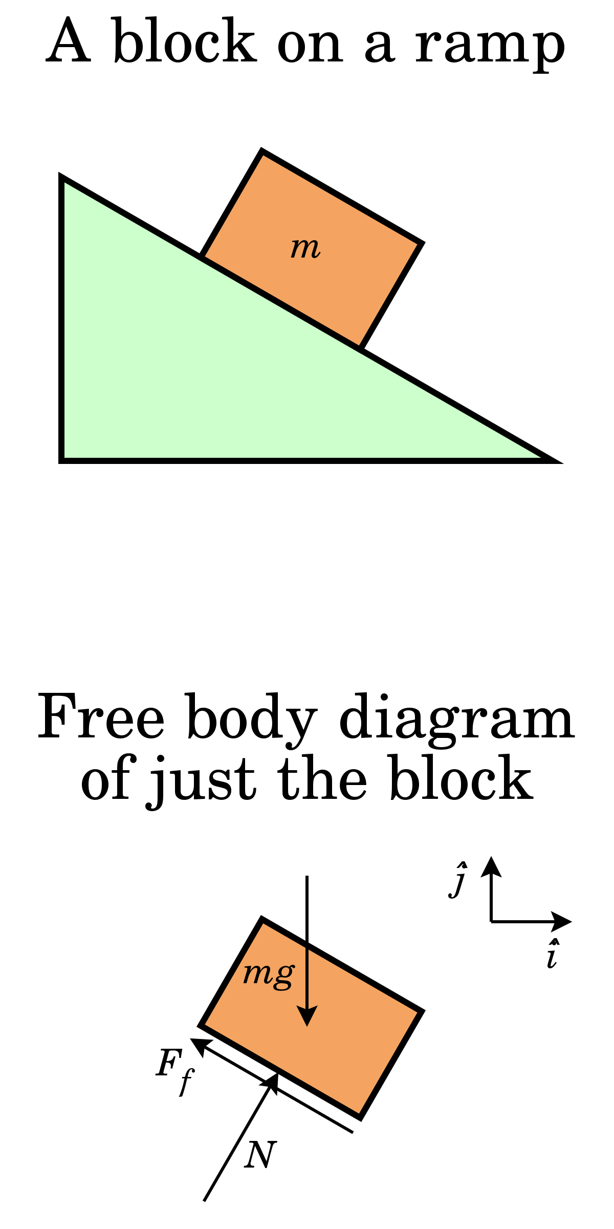
A free-body diagram is a diagram that clearly indicates all forces acting on a body, in this case the body being the truss. As an example, consider this crate suspended from two cords. The forces exerted at point A are the force of tension from the cord on the left, the force of tension from the cord on the right and the force of the weight of the crate due to gravity pulling down. These ...
Analysis Of Structures
the entire truss and determine all the support reactions using the equations of equilibrium. 2. Draw the free-body diagram of a joint with one or two unknowns. Assume that all unknown member forces . act in tension (pulling the pin) unless you can determine by inspection that the forces are compression loads. 3.

Pinned Truss Freebody Diagram Fbd Stress Ebook Llc
∑ ↑+ 0 = ⇒ − + = 4 1 0 y Ay ⇒ Αy = 3 kΝ ∑ 0 = ⇒ − + = 1 0 x Ax ⇒ Αx = 1 kΝ . Having calculated the reactions, we draw the free body diagram of the truss and start analyzing the joint equilibrium, where, concurrent are only two unknown forces.

Draw The Free Body Diagram Of The Truss Determine A Why Is There Two 6kn 2m When Summing Moments About Point A B Should The A X Be Negative Because It Has To Face The
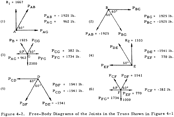
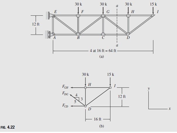
The free-body diagram of the right portion of the truss, which is the easiest to analyze, is shown in the following figure: 20. Equations of Equilibrium: We will apply the moment equation about point 0 in order to eliminate the two unknowns F FG and FcD.

Free Body Diagram Of Truss Analogy Approach For Overlaid Beams Download Scientific Diagram
≡ involves cutting the truss into two portions (free body diagrams, FBD) by passing an imaginary section through the members whose forces are desired. Desired member forces are determined by considering equilibrium of one of the two FBD of the truss. 23 Method of sections can be used to determine three unknown member forces per FBD since all three equilibrium equations can be used. Method of ...

Trusses And Frames
1.Draw Free Body Diagram of Truss 2.Determine external reactions by applying equilibrium equations to the whole truss 3.Perform the force analysis of the remainder of the truss by Method of Joints. Structural Analysis: Plane Truss Method of Joints • Start with any joint where at least one known load exists and where not more than two unknown forces are present. FBD of Joint A and members AB ...
Trusses Frames And Machines Analysis Of Statically Determinate Trusses
The free-body diagram of the truss as a whole is used for the calculation of reactions, and another set of free-body diagrams is used for the calculation of member forces. We will discuss the latter case in a later section. Let us now develop the free body diagram of a truss for the calculation of its support reactions. The nine-bar truss shown ...

Calculating The Truss Member Forces Pdf
Space Truss: Example Using Scalar equations of equilibrium at joints D and C will give: Joint B: Draw the Free Body Diagram Scalar equations of equilibrium may be used at joint B ME101 - Division III Kaustubh Dasgupta 6

The Analysis Of Trusses Docsbay
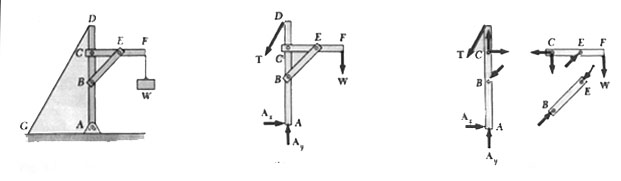
• A free body diagram of the complete frame is used to determine the external forces acting on the frame. • Internal forces are determined by dismembering the frame and creating free-body diagrams for each component. • Forces between connected components are equal, have the same line of action, and opposite sense.
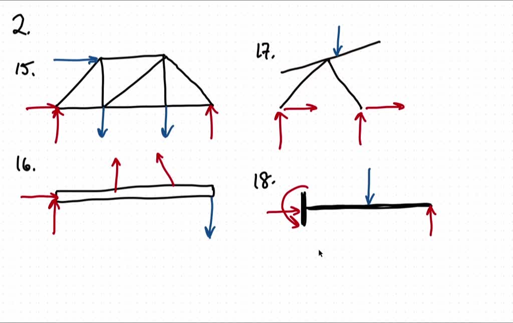
Solved Draw The Free Body Diagram For The Following Problems A The Truss In Prob 5 15 B The Beam In Prob 5 16 C The Man And Load In Prob 5 17 D The Beam In
Transcribed image text: NOTE: This is a multi-part question. Once an answer is submitted, you will be unable to return to this part. Consider the given structure with P=64 kN. 4.5 m ΡkΝ OE 3.2 m - 6 m - 6 m 2 12 of 2 Next > Required information Draw the free body diagram of the truss, joint E joint D. and joint C.
Gaussian Reduced Eschelon Form
Consider the two bar truss again, shown below as a free body diagram. Free body diagram of a 2-bar truss. The joint resolution method requires us to evaluate the sum of the forces meeting at a joint. These forces can be resolved into two orthogonal (mutually perpendicular) directions allowing us to evaluate two equations of force equilibrium. Thus we have two equations from which we can ...

For The Truss Shown Below 1 Draw A Free Body Diagram And Determine The Reactions At Homeworklib
Free Body Diagram Questions and Answers. Get help with your Free body diagram homework. Access the answers to hundreds of Free body diagram questions that are explained in a way that's easy for ...
Forces And Free Body Diagrams Ppt Download
Fig.1: Free Body Diagram for Truss. Please observe in the above picture, FBD of the whole truss is drawn so the unnecessary member details have not been shown. Also observe the actual reactions at P and Q has been replaced by reaction forces in the FBD. Typically in plane truss, joint at P is of hinge joint type and at Q is of roller (sliding ...
Iitg Ac In
1. Draw a free-body diagram of the entire structure and determine the reactions (if r = 3). 2. Draw free-body diagrams for all members (assume tensile forces in all members) and all joints. 3. Set up the equilibrium equations for each joint and solve them one joint at a time, begin with those that have at most two unknowns. 4.

Builder S Engineer 2013

Mechanics Map Method Of Joints
Truss Analysis Tutorial Method Of Joints And Sections Degreetutors Com
Ppt Free Body Diagrams Powerpoint Presentation Free Download Id 3812066
Trusses Engineering Library

What Is A Truss A Structure Composed Of Members Connected Together To Form A Rigid Framework Usually Composed Of Interconnected Triangles Members Carry Ppt Video Online Download
Free Body Diagram Wikipedia
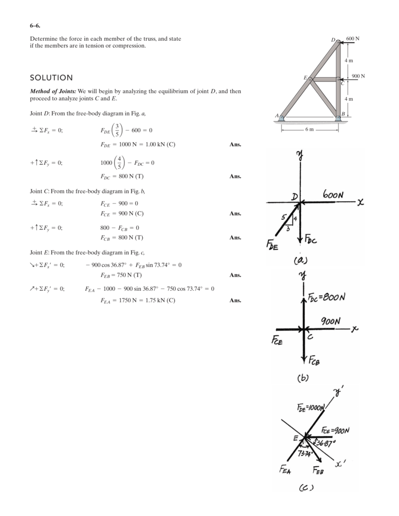
Solution

This Structure Called A Truss Has A Pin Support At A And A Roller Support At B And Is Loaded By Two Forces Determine The Reactions At The Supports Strategy Draw A
En3a Hw7

Free Body Diagrams Method Of Joints Concurrernt Truss Nodes Multiple Ways Engineering Physics Series Module 3s Book 1 Cherchuk R N Ebook Amazon Com

Truss Free Body Diagram 1 Define Truss And Rules For Fbd Youtube
Truss Analysis Tutorial Method Of Joints And Sections Degreetutors Com
1

Port Or Al Fr F Am Es B Rangka Batang Trusses C Machines Pdf Download Gratis
Plane Trusses By The Method Of Sections Problems And Solutions Civil Engineering

Part A The Truss Is Supported By A Pin At A And A Roller At B Figure 1 Draw The Free Body Diagram Of The Truss Draw The Vectors Starting At The Black Dots

Determine The Force In Each Member Of The Truss By Method Of Joints

Principles Of Engineering At Rmhs A Brief Introduction To Some New Key Concepts
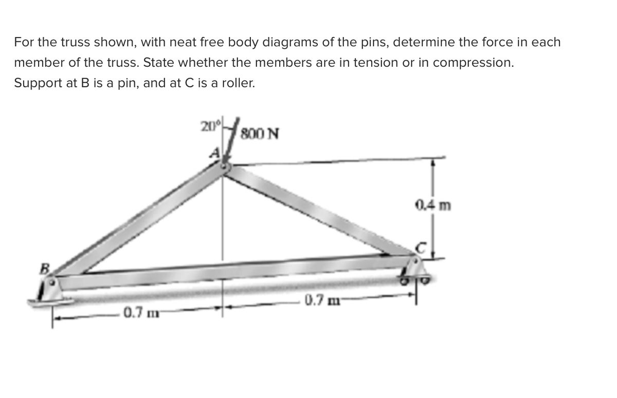
Answered For The Truss Shown With Neat Free Bartleby
0 Response to "36 truss free body diagram"
Post a Comment