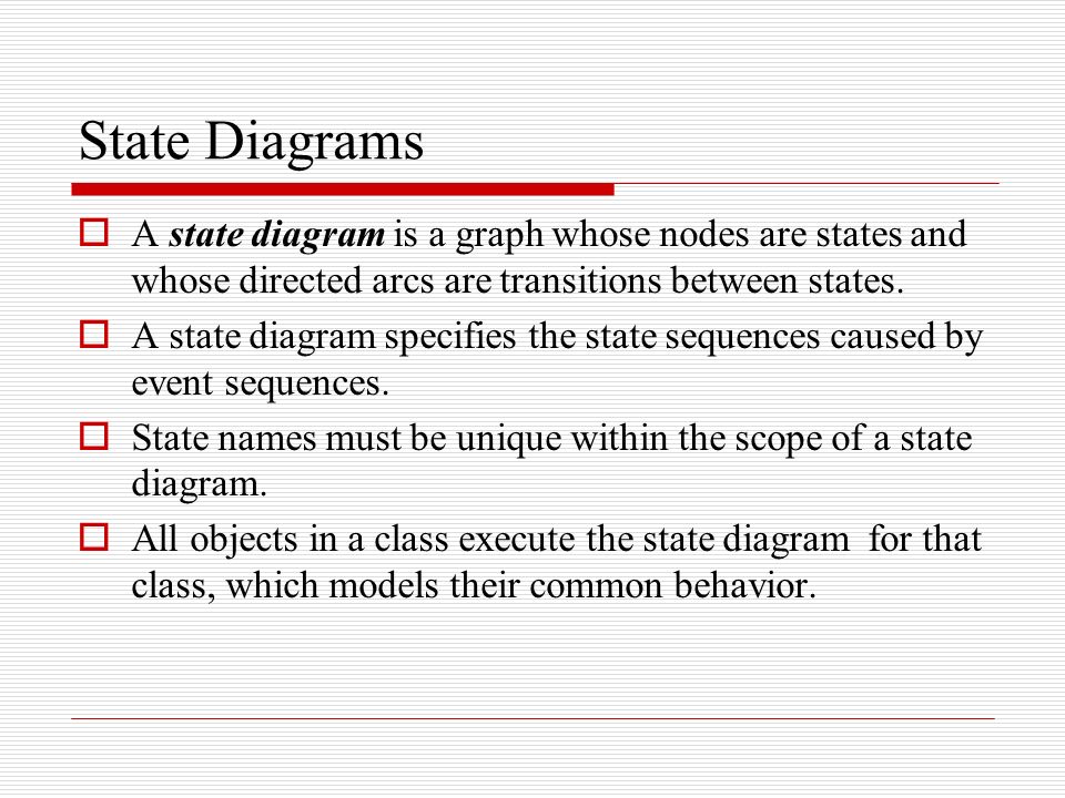
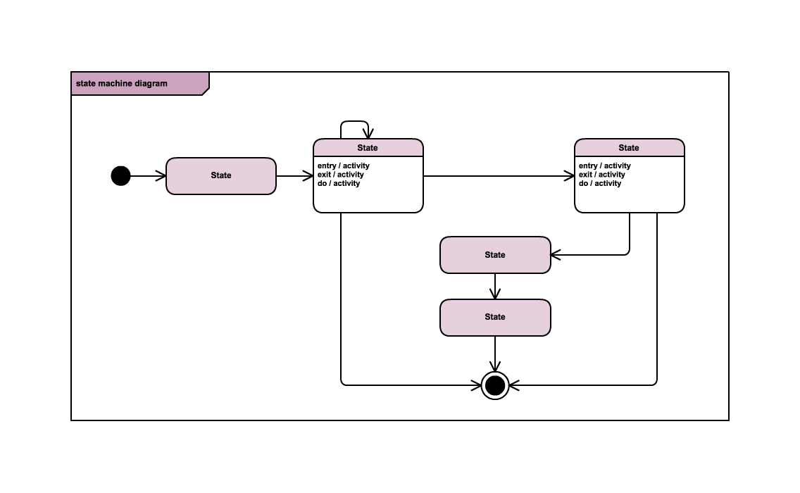
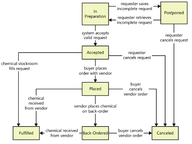
36 in a state transition diagram, the states appear as rounded rectangles with the state names inside.
In a state transition diagram,the states appear as rounded rectangles with the state names inside. Posted on. July 15, 2021 by quizs. A transition between one state into another state occurs because of some triggered event. To draw a state diagram in UML, one must identify all the possible states of any particular entity. The purpose of these UML diagrams is to represent states of a system. States plays a vital role in state transition diagrams.
In a state transition diagram, the circle to the left is the final state. False In a state transition diagram, the states appear as rounded rectangles with the state names inside.

In a state transition diagram, the states appear as rounded rectangles with the state names inside.
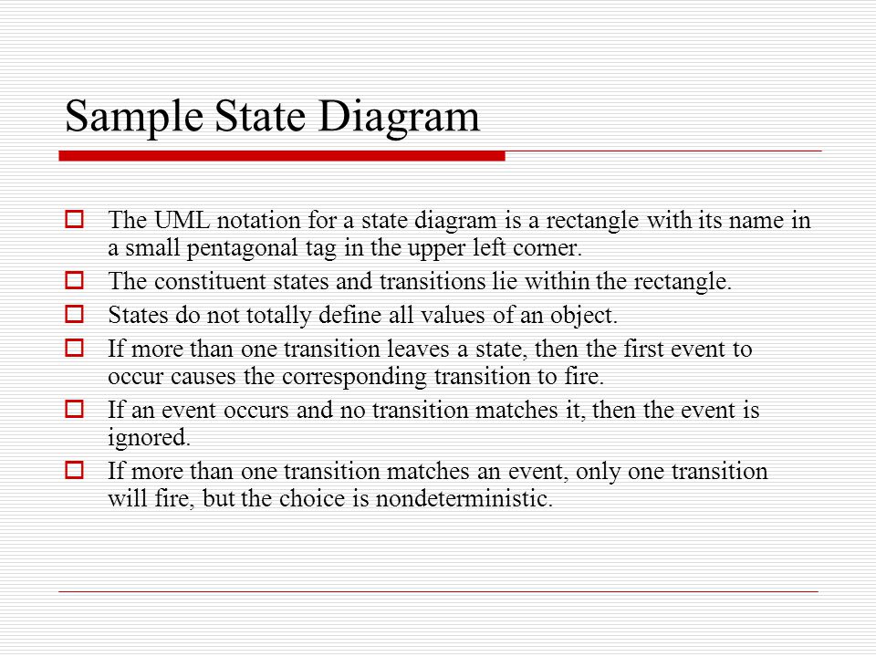
Packages appear as rectangles with small tabs at the top. The package name is on the tab or inside the rectangle. ... From each state comes a complete set of transitions that determine the subsequent state. States are rounded rectangles. Transitions are arrows from one state to another. ... Our diagram has two self-transition, one on Getting ... From each state comes a complete set of transitions that determine the subsequent state. Hide image. States are rounded rectangles. Transitions are arrows from one state to another. Events or conditions that trigger transitions are written beside the arrows. Our diagram has two self-transition, one on Getting SSN and another on Getting PIN. In a state transition diagram, the states appear as rounded rectangles with the state names inside. True In a sequence diagram, a message is identified by a narrow vertical shape that covers the lifeline.
In a state transition diagram, the states appear as rounded rectangles with the state names inside.. In a state transition diagram, the states appear as rounded rectangles with the state names inside. T 22. In a state transition diagram, the circle to the left is the final state. F 23. A class diagram resembles a horizontal flowchart that shows the actions and events as they occur. F 24. Finite state machines and their corresponding state-transition diagrams (or state diagrams for short) are the formal mechanism for collecting such fragments into a whole. State diagrams are simply directed graphs, with nodes denoting states, and arrows (labelled with the triggering events and guarding conditions) denoting transitions. The UML uses a set of symbols to represent graphically the ____ within a system. ... In a state transition diagram, the states appear as rounded rectangles ... The UML state diagrams are directed graphs in which nodes denote states and connectors denote state transitions. For example, Figure 1 shows a UML state diagram corresponding to the computer keyboard state machine. In UML, states are represented as rounded rectangles labeled with state names.
In a state transition diagram, the states appear as rounded rectangles with the state names inside. True In a sequence diagram, a message is identified by a narrow vertical shape that covers the lifeline. In a state transition diagram, the states appear as rounded rectangles with the state names inside. True False. True. A _____ is a visual summary of several related use cases within a system or subsystem. a. use case matrix b. use case description c. use case diagram d. use case schema. Use Case Diagram. A(n) _____ represents the steps in a specific business function or process. a. data flow ... Harry J. Rosenblatt · 2013 · ComputersIn a state transition diagram, the states appear as rounded rectangles with the state names inside. The small circle to the left is the initial state, ... All possible states must be documented in the state transition diagram. State appear as rounded rectangles with the state names inside.
What is the State transition Diagram? When we write our program in Object-oriented programming, then we need to take classes and objects. Objects change their states during different functions/actions performed on objects. In a state transition diagram, the states appear as rounded rectangles with the state names inside. ◦All possible states must be documented in the state transition diagram ◦States appear as rounded rectangles with the state names inside. State Transition Diagrams • Fancy version of a DFA • Shows the possible states of the object and the transitions that cause a change in state - i.e. how incoming calls change the state • Notation - States are rounded rectangles - Transitions are arrows from one state to another. Events or In a state transition diagram, the states appear as rounded rectangles with the state names inside. True. Inheritance enables an object, called a _____, to derive one or more of its attributes from a parent. child. A _____ is a command that tells an object to perform a certain method. message. A _____ graphically documents a use case by showing the classes, the messages, and the timing of the ...
State Machine Diagram In Uml What Is Statechart Diagram
- A betting round occurs, followed by dealing 3 shared cards from the deck. - As shared cards are dealt, more betting rounds occur, where each player can fold, check, or raise. - At the end of a round, if more than one player is remaining, players' hands are compared, and the best hand wins the pot of all chips bet so far.
State Diagrams A State Diagram Is A Graph Whose Nodes Are States And Whose Directed Arcs Are Transitions Between States A State Diagram Specifies The Ppt Video Online Download
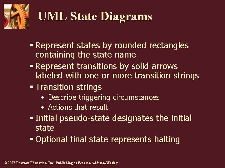
Activity Diagram: Example 55. State Transition Diagrams • Fancy version of a DFA • Shows the possible states of the object and the transitions that cause a change in state - i.e. how incoming calls change the state • Notation - States are rounded rectangles - Transitions are arrows from one state to another.

All Diagram Objects Creately
User input in the state diagram editor. Response in the state diagram. Description. Focus on a composite state. The composite state is editable. You can edit the name through two single clicks on the name. You can add outgoing transitions via the command icons that are shown above the state. The size of the composite state is adjustable.
Uml State Diagrams 2007 Pearson Education Inc Publishing
States are denoted with rectangles with rounded corners. Each rectangle is labeled with the name of the state. And transitions are marked with arrows that link one state to another, showing how the states change. You’ll find a run through of the most popular symbols below. Composite state (also known as a ‘nested state’) This refers to a state that encompasses various sub-states, which ...

Activity Diagram Activity Diagram Symbols Examples And More
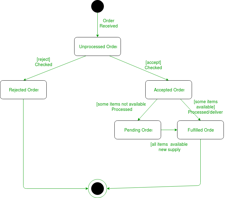
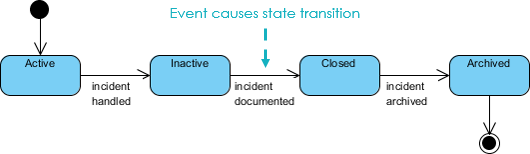
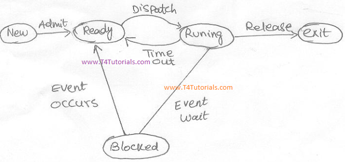
5/16/2015 12 FIGURE 6-33 An example of a state transition diagram for a bank account State Transition Diagrams Shows how an object changes from one state to another, depending on events that affect the object All possible states must be documented in the state transition diagram States appear as rounded rectangles with the state names inside CIS 2321 Summer 2015 FIGURE 6-34 An activity diagram ...
4 State Transitions Diagrams
In a state transition diagram, the states appear as rounded rectangles with the state names inside. asked Aug 11, 2019 in Computer Science & Information Technology by phviking11 Answer the following statement true (T) or false (F)

In A State Transition Diagram The States Appear As Rounded Rectangles With The Course Hero
Fals e ANSWER: True RATIONALE: In a state transition diagram, the states appear as rounded rectangles with the state names inside. POINTS: 1 DIFFICULTY: Moderate REFERENCES: 193 QUESTION TY PE: True / False HAS VARIABL ES: False LEARNING OB JECTIVES: SAD.12e.06.09 - Demonstrate use of the UML to describe object- oriented systems, including use ...
2
All possible states must be documented in the state transition diagram. - Ex. bank account can be opened as NEW then changed to ACTIVE or EXISTING, then be CLOSED or FROZEN - states appear as rounded rectangles with state names inside - filled circle represents start of workflow - encircled filled circle represents end state: Term. Activity Diagrams: Definition. resembles a horizontal ...
Wcw Cs Ui Ac Id
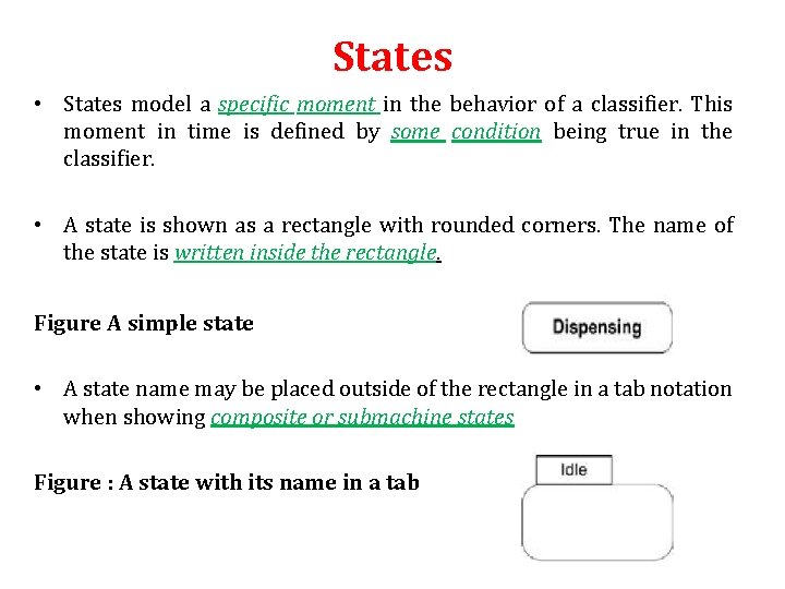
Simple state is shown as a rectangle with rounded corners and the state name inside the rectangle. Simple state Waiting for Customer Input. Optionally, state may have state name placed inside an attached name tab. The name tab is a rectangle, usually resting on the outside of the top side of a state. Simple state may have compartments. The compartments of the state are: name compartment ...

All Diagram Objects Creately
From each state comes a complete set of transitions that determine the subsequent state. Hide image. States are rounded rectangles. Transitions are arrows from one state to another. Events or conditions that trigger transitions are written beside the arrows. Our diagram has two self-transition, one on Getting SSN and another on Getting PIN.
Unified Modeling Language Uml State Diagrams Geeksforgeeks
Activity diagrams show the flow of control and activities as rounded rectangles. Activities are typical action states - states that transit automatically to the next state after the action is complete. The filled-in circle represents the start of the activity diagram where the flow of control starts.

Sparx Eu State Machine Diagram
NOTES: most Stateflow charts use a mixture of State diagrams and Flow Charts ... Conditions appear as labels for the transition, enclosed in square brackets ([ ]). 10 Terms: Transition Notation A transition is characterized by its label. The label can consist of an event, a condition, a condition action, and/or a transition action. The ? character is the default transition label. Transition ...
1
State-Transition Diagram Components. There are two major components for this diagram: States, Changes of State, and Conditions and Actions. · System States are represented by rectangles. States are the sets of circumstances or attributes characterizing a person or thing at a given time.

Software Engineering Mr Ahmad Al Ghoul
To move/reshape a transition, first select it, then some small rectangles will appear along the arc. Select and move the rectangles to move/reshape the arc. 11.2.7 Slave Processes of States In an FSM, each state may be associated with a slave process. This slave process could be a subsystem of any other Ptolemy domain or be another FSM Galaxy.
2
In a state transition diagram, the states appear as rounded rectangles with the state names inside. actor In a use case, an external entity, called a(n) _____, initiates a use case by requesting the system to perform a function or process.
A Simple Guide To Drawing Your First State Diagram With Examples Cacoo
Question 82 Complete Mark 1.00 out of 1.00 Flag question Question text In a state transition diagram, the states appear as rounded rectangles with the state names inside. Select one: True False

Pseudostates An Overview Sciencedirect Topics
In a state transition diagram, the states appear as rounded rectangles with the state names inside. True In a sequence diagram, a message is identified by a narrow vertical shape that covers the lifeline.

Uml 2 State Machine Diagrams An Agile Introduction
From each state comes a complete set of transitions that determine the subsequent state. Hide image. States are rounded rectangles. Transitions are arrows from one state to another. Events or conditions that trigger transitions are written beside the arrows. Our diagram has two self-transition, one on Getting SSN and another on Getting PIN.

Cse 403 Lecture 9 Uml State Diagrams Reading Ppt Download
Packages appear as rectangles with small tabs at the top. The package name is on the tab or inside the rectangle. ... From each state comes a complete set of transitions that determine the subsequent state. States are rounded rectangles. Transitions are arrows from one state to another. ... Our diagram has two self-transition, one on Getting ...

Uml 2 State Machine Diagrams An Agile Introduction

State Diagrams Everything To Know About State Charts

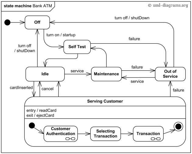
Design Elements Bank Uml State Machine Diagram Design Elements Uml State Machine Diagrams Uml State Machine Diagram Template State Diagram Symbola

Uml State Machine Komputer Telekomunikasi 1 3073 P2k Unhamzah Ac Id

State Machine Diagram Uml 2 Tutorial Sparx Systems
State Diagrams A State Diagram Is A Graph Whose Nodes Are States And Whose Directed Arcs Are Transitions Between States A State Diagram Specifies The Ppt Download
Uml State Diagrams With Draw Io Draw Io

Statechart Diagram Staruml Documentation
All You Need To Know About State Diagrams

Practical Uml
Unit 4 Behavioral Diagrams P P Mahale Behavioral
State Transition Diagram With Example In Software Engineering T4tutorials Com
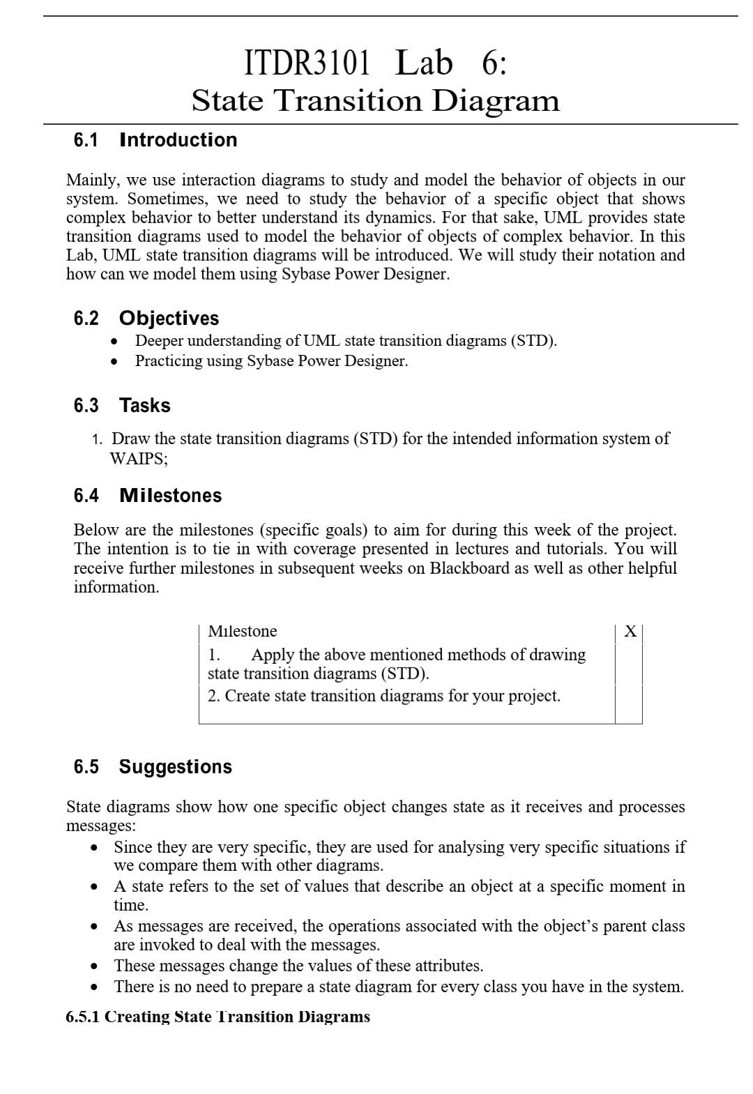
Solved Itdr3101 Lab 6 State Transition Diagram 6 1 Chegg Com
A Simple Guide To Drawing Your First State Diagram With Examples Cacoo

An Introduction To State Diagrams Business Analyst Learnings

In A State Transition Diagram The States Appear As Rounded Rectangles With The Course Hero
Modeling System States State Transition Diagrams And State Tables By Karl Wiegers Analyst S Corner Medium
0 Response to "36 in a state transition diagram, the states appear as rounded rectangles with the state names inside."
Post a Comment