40 ttt diagram for eutectoid steel
Iron Carbon Ttt Diagram - schematron.org ttt diagram is a plot of temperature versus the logarithm of time for a steel alloy of the complete isothermal transformation diagram for an iron-carbon alloy.c metastable equilibrium diagram and ttt diagrams for plain carbon hypoeutectoid, eutectoid and hypereutectoid steels m s (a) fe-fe 3 c metastable phase diagram (b) ttt diagram for … TTT diagram for steel, eutectoid steel - LearnMech TTT Diagram For Eutectoid Steel ( Isothermal Transformation Diagram ) Time-Temperature-Transformation (TTT) diagram or S-curve refers to only one steel of a particular composition at a time, which applies to all carbon steels. This diagram is also called as C-curve isothermal (decomposition of austenite) diagram and Bain's curve.
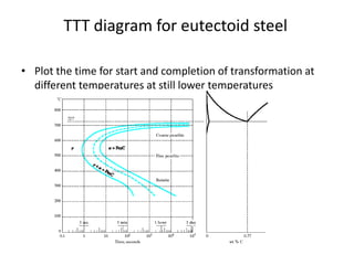
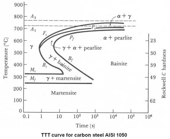
TTT Diagrams: Introduction and Limitations | Material ... As shown in complete TTT diagram for eutectoid steel in figure above approximately 550°C-600°C, austenite transforms completely to pearlite. Below this range up to 450°C, both pearlite and bainite are formed. Finally, between 450°C and 210°C, the reaction product is bainite only.

Ttt diagram for eutectoid steel
Hypoeutectoid Steel - an overview | ScienceDirect Topics TTT diagrams for (a) eutectoid, (b) hypoeutectoid, and (c) hypereutectoid steels. (b) and (c) show (dashed lines) the C-curves for the formation of primary α and Fe 3 C, respectively. Note that as the carbon content increases, both M s and M F decrease. Solved 1. Using the TTT diagram for Eutectoid Steel ... Using the TTT diagram for Eutectoid Steel, specify the constituents and their approximate percentages of a small specimen subjected to the following time-temperature treatments. All begin with a completely Austenized specimen: - Rapidly cool to 650°C, hold for 100 seconds, then quench to room temperature. Austenite - an overview | ScienceDirect Topics If austenite is allowed to transform just below 996 K, the reaction product, as predicted by the Fe–Fe 3 C phase diagram, is the α−Fe+Fe 3 C eutectoid. This eutectoid constituent is known as pearlite and consists of alternate platelets of ferrite (α-Fe) and cementite (Fe 3 C), the former being the continuous phase.
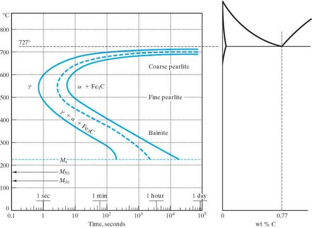
Ttt diagram for eutectoid steel. PDF Lecture 19: Eutectoid Transformation in Steels: a typical ... A sample of the eutectoid composition is cooled from a single-phase region (γ) to a temperature (T) below the eutectoid temperature (T E). The following diagram shows a part of the iron-carbon phase diagram. Concentrations C 1, C 2, C 3, C 4are various equilibrium ( stable as well as metastable ) concentrations of carbon. c α C Fe-C diagram - SlideShare Nov 18, 2013 · Iron–Carbon Phase Diagram • In their simplest form, steels are alloys of Iron (Fe) and Carbon (C). • The Fe-C phase diagram is a fairly complex one, but we will only consider the steel and cast iron part of the diagram, up to 6.67% Carbon. 3. Fe – C Equilibrium Diagram 4. What is the eutectoid composition? TTT curve of eutectoid steel superimposed on iron carbon phase diagram. The curve is prepared by heating steel samples to the austenitizing temperature of 1,550°F (845°C). These samples are then quenched to a set of temperatures below 1,300°F (700°C). Phase Diagrams, TTT plots & CCT diagrams | beng-project Iron-Iron Carbide Phase Diagram - Callister. Austenite is a polymorph of iron, in a face centred cubic (FCC) structure. Carbon is relatively soluble in this phase (up to 2% C at 1100°C). It is therefore found in mild carbon steel above the eutectoid temperature of 727°C. As it cools, the austenite transforms into the much less carbon soluble ...
The TTT Diagram for Eutectoid Steel - Making Things Fast ... We'll examine the lead-tin phase diagram and look at its practical applications as an example of making something slowly. Then we'll evaluate the TTT diagram for eutectoid steel, and compare diffusional to diffusionless transformations with the TTT diagram, monitoring how we make things rapidly. Lesson ten is a brief history of semiconductors. TTT Diagram for Eutectoid Steel | TTT Phase diagram ... #modimechanicalengineeringtutorials, #mechanicalmagicmechanicallearningtutorials,Welcome to My YouTube Channel MODI MECHANICAL ENGINEERING TUTORIALS.This ch... Ttt diagram for eutectoid steel(bainite, spherodite ... TTT DIAGRAM FOR EUTECTOID STEEL(BAINITE, SPHERODITE, MARTENSITE) 4PRESENTED BY DARSHIT DESAI. BAINITE • The microstructure of bainite consists of ferrite and ... PDF T-t-t Diagram for Eutectoid Steel TTT Diagram For Eutectoid Steel ( Isothermal Transformation Diagram ) Time-Temperature-Transformation (TTT) diagram or S-curve refers to only one steel of a particular composition at a time, which applies to all carbon steels. This diagram is also called as C-curve isothermal (decomposition of austenite) diagram and ain's curve.
TTT diagram of Hypoeutectoid and Hypereutectoid steels ... TTT diagram of hypoeutectoid and hypereutectoid steels Time Temperature Transformation (TTT) of Austenite ... Compare TTT diagrams for hypoeutectoid, eutectoid and the hypereutectoid steels in Fig. 3.6. The incubation period is maximum (critical cooling rate is slowest) in eutectoid steel. M s temperatures are uniformly decreasing in the whole range of carbon. Bainitic part is uniformly shifted to the right. (b) Effect of Alloying Elements: PDF Time-Temperature-Transformation (TTT) Curves eutectoid steel cooled from austenite phase at 800 c ,then cooled as (ttt diagram ) as below , find the final structure if cooling path as following : 1- rapid cooling to (350 c) and hold to( 104sec) , then rapid cooling to room temperature . 2- rapid cooling to (650 c) and hold to( 20 sec) , then, rapid cooling to )400 c) and hold at … Ttt Diagram For Eutectoid Steel - schematron.org Ttt Diagram For Eutectoid Steel. It graphically describes the cooling rate required for the transformation of austenite to pearlite, bainite or martensite. • TTT diagram also gives. TTT diagram is a plot of temperature versus the logarithm of time for a It is also called isothermal transformation diagram. Pearlite.
TTT Diagram... - Metallurgical and Materials Engineering, FPI ...
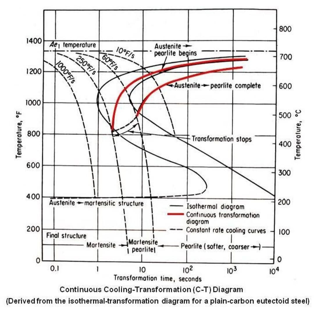
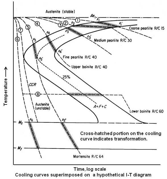
PDF Continuous Cooling Transformation (CCT) Diagrams TTT diagram ( ) of eutectoid steel t' ... required to nucleate pearlite as per TTT diagram in Fig. 8. But material has spent t 1 timing at higher than T 1 temperature in case of continuous cooling and incubation period at higher temperature is much more than t 1. The nucleation condition

Continuous cooling transformation - Wikipedia
PDF Time-temperature- Transformation Diagram TTT Diagram On the other hand, TTT diagram is a more practical diagram. It shows what structures can be expected after various rates of cooling. It graphically describes the cooling rate required for the transformation of austenite to pearlite, bainite or martensite. TTT diagram also gives the temperature at
![TTT diagram for 4340 [10]. 1% ferrite at 150 s, 1% pearlite ...](https://www.researchgate.net/profile/Magnus-Ahlfors/publication/316873142/figure/fig4/AS:668797056868361@1536465052581/TTT-diagram-for-4340-10-1-ferrite-at-150-s-1-pearlite-at-2000-s-and-99-pearlite-at.jpg)
TTT diagram for 4340 [10]. 1% ferrite at 150 s, 1% pearlite ...
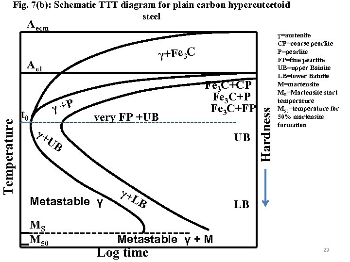
PDF TTT & CCT Diagram Part 2 Lect-6 - University of Technology ... hypoeutectoid steel and by cementite in hypereutectoid steel. Schematic T TT diagrams for eutectoid, hypoeutectoid and hyper eutectoid steel are shown in Fig.", Figs. 7(a)-(b) and all of them together along with schematic Fe-Fe3C metastable equilibrmm are shown in Fig. 8.

Time Temperature Transformation (TTT) Diagrams - ppt download
TTT diagram of eutectoid steel and martensitic transformation TTT diagram SMALL ARMS FACTORY (MINISTRY OF DEFENSE) THE NATURE OF MATERIALS Lionel Wolberger. Test 2 Polymer Notes sad asad. Diffusion guest5497e1. Diffusion Jose Surendran. AieeeChemistry 2005 ... TTT diagram of eutectoid steel and martensitic transformation 1.
![TTT diagram for 0.65 % carbon steel [3] | Download Scientific ...](https://www.researchgate.net/profile/Novan-Tofany/publication/257378538/figure/fig1/AS:669039516991514@1536522859947/TTT-diagram-for-065-carbon-steel-3.png)
TTT diagram for 0.65 % carbon steel [3] | Download Scientific ...
TTT Diagram of steel in Material science - Materials Today Mar 29, 2020 · Presented above is the TTT-diagram for eutectoid steel. For each composition, there will be a slight variation in diagram curves. TTT diagram of steel indicates the time-temperature and transformation curve. This means transformation is dependent upon time, temperature, and cooling mechanism. Difference between phase diagram and TTT diagram of ...

TTT Diagram Example | Engineering Materials
The Iron Carbon Phase Diagram Due time, however, means millennia and more at room temperature for plain carbon steel. Cementite, in other words, is a very long-lived metastable phase under normal conditions. It thus makes sense to use it for something that is not a true phase diagram for purists, but that sane normal folks will call "phase diagram" anyway.

TTT Diagrams: 1. The Basic Idea
PDF Time Temperature Transformation (TTT) Diagrams It is also called isothermal transformation diagram Definition: TTT diagrams give the kinetics of isothermal transformations. 2 Determination of TTT diagram for eutectoid steel Davenport and Bain were the first to develop the TTT diagram of eutectoid steel. They determined pearlite and bainite portions whereas Cohen later modified and included M
TTT diagram
Eutectoids - an overview | ScienceDirect Topics TTT diagrams for (a) eutectoid, (b) hypoeutectoid, and (c) hypereutectoid steels. (b) and (c) show (dashed lines) the C-curves for the formation of primary α and Fe 3 C, respectively. Note that as the carbon content increases, both M s and M F decrease.

TTT curves for (A) UNS G41400 (SAE/AISI 4140) steel (0.37-wt ...
TTT diagram - SlideShare Complete TTT (isothermal transformation) diagram for eutectoid steel. 38. Time Temperature Transformation (TTT) Diagram • Below A1 , austenite is unstable, i.e., it can transform into pearlite, bainite or martensite. • The phases finally formed during cooling depend upon time and temperature.

Constant temperature transformation TTT curves :: Total ...
酸化スケールの相変態挙動とその ... - Nippon Steel Produced TTT diagram for the bilayer scale of Fe 3 O 4 and FeO : Scale remains initial structure, : Fe 3 O 4 precipitations are generated from the Fe 3 O 4 /FeO interface, : Eutectoid structure of Fe 3 O 4 and ferrite appears, : Granular Fe 3 O 4 precipitations are generated from the inside of the FeO, : Granular Fe 3 O 4

File:TTT diagram-20201211-constant cooling rate ...
TTT diagram indicates time, temperature and transformation of Explanation: TTT Diagram: The rate of phase transformation also depends upon the temperature.; Temperature-time-transformation diagram (TTT), also known as isothermal transformation curves, are useful in planning heat treatments. The complete isothermal transformation diagram for an iron-carbon alloy of eutectoid composition A (austenite), B (Bainite), M (Martensite), P (Pearlite) is below:
Fe-Fe3C T-T-T Diagram | Metallurgy for Dummies
The TTT Diagram for Eutectoid Steel - Making Things Fast ... We'll examine the lead-tin phase diagram and look at its practical applications as an example of making something slowly. Then we'll evaluate the TTT diagram for eutectoid steel, and compare diffusional to diffusionless transformations with the TTT diagram, monitoring how we make things rapidly. Lesson ten is a brief history of semiconductors.
TTT/CCT Hesaplamaları – JMatPro
PDF EXPERIMENT 6 HEAT TREATMENT OF STEEL eutectoid ... Steel with a 0.78 wt% C is said to be a eutectoid steel. Steel ... (TTT) diagram shown in Figure 6-2. As a sample is cooled, the temperature will decrease as shown in curve #1. At point A, pearlite (a mixture of ferrite and cementite) will start to form from ... Isothermal transformation diagrams for SAE 1045 steel are shown in Figure 6-4. Heat ...
TTT diagrams Determination of TTT diagram for eutectoid steel
(PDF) SOLUTIONS MANUAL FUNDAMENTALS OF MODERN ... - Academia.edu solutions manual fundamentals of modern manufacturing: materials, processes, and systems second edition
T-T-T Diagram & Basics of Heat Treatment
Effect of Alloying elements in Steel, TTT diagram and ... Effect of Alloying elements in Steel, TTT diagram and Phase transformation diagram Metals , Steel Literature / March 30, 2020 September 14, 2021 It's a long-standing tradition to discuss the effect of alloying elements in steel to achieve better properties like Nickel make steel tougher and chromium makes steel harder.

Isothermal transformation diagram - Wikipedia
Austenite - an overview | ScienceDirect Topics If austenite is allowed to transform just below 996 K, the reaction product, as predicted by the Fe–Fe 3 C phase diagram, is the α−Fe+Fe 3 C eutectoid. This eutectoid constituent is known as pearlite and consists of alternate platelets of ferrite (α-Fe) and cementite (Fe 3 C), the former being the continuous phase.
Nucleation and Growth in a Eutectoid Steel
Solved 1. Using the TTT diagram for Eutectoid Steel ... Using the TTT diagram for Eutectoid Steel, specify the constituents and their approximate percentages of a small specimen subjected to the following time-temperature treatments. All begin with a completely Austenized specimen: - Rapidly cool to 650°C, hold for 100 seconds, then quench to room temperature.
EN380 Quiz #4 Solution
Hypoeutectoid Steel - an overview | ScienceDirect Topics TTT diagrams for (a) eutectoid, (b) hypoeutectoid, and (c) hypereutectoid steels. (b) and (c) show (dashed lines) the C-curves for the formation of primary α and Fe 3 C, respectively. Note that as the carbon content increases, both M s and M F decrease.
TTT diagrams for eutectoid and 4340 steel alloys
TTT & CCT Diagram Part 2 Lect-6

TTT Diagram of steel in Material science - Materials Today

Time Temperature Transformation Worksheet Problem

3. Below is a TTT diagram for hypereutectoid steel | Chegg.com

File:DiagrammeTTT.GIF - Wikimedia Commons
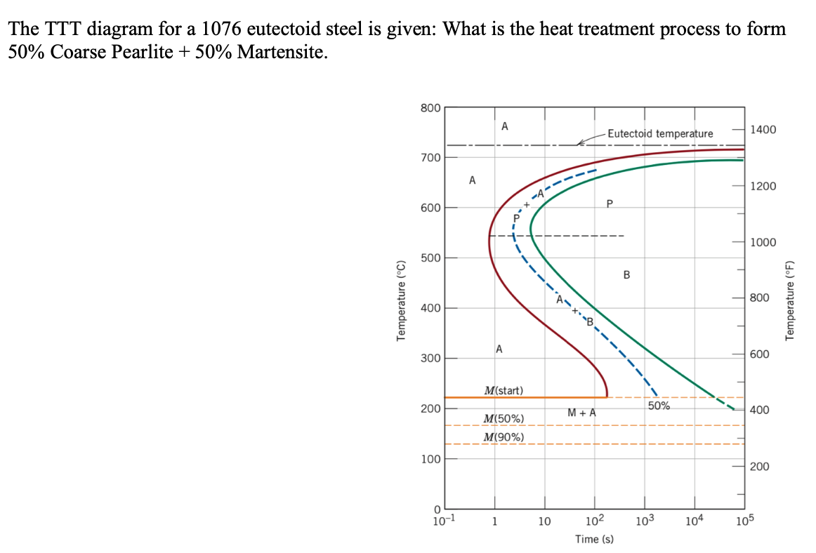
Answered: The TTT diagram for a 1076 eutectoid… | bartleby
Steels - An Introduction to Heat Treatment

TTT Diagrams - for Steel

Time Temperature Transformation (TTT Diagram) - PowerPoint Slides

TTT Diagram Basic - TTT diagram for steel, eutectoid steel
Practical Maintenance » Blog Archive » I-T Diagram and ...

TTT CURVE ~ MECHTECH GURU

TTT Diagrams: 1. The Basic Idea
Kinetics and Heat Treatments in Metals

TTT Diagram of steel in Material science - Materials Today
Practical Maintenance » Blog Archive » I-T Diagram and ...
Martensite point
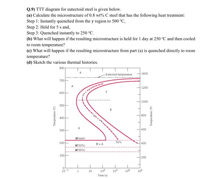
Solved Q.9) TTT diagram for eutectoid steel is given below ...
Time Temperature Transformation TTT Diagrams R Manna Assistant
Answered: 3.The TTT diagram of a plain carbon… | bartleby

15n20 ttt diagram? Bainite questions - Metallurgy and other ...
0 Response to "40 ttt diagram for eutectoid steel"
Post a Comment