39 4 point fft butterfly diagram
DIT-FFT - 4 point Butterfly diagram |dsp\dtsp | Видео Butterfly diagram for 4-point DFT (DIT-FFT)Подробнее. dit fft example -(Decimation In Time Fast Fourier Transform)Подробнее. Decimation In Time FFT(DIT), Letus Learn to draw Butterfly Diagram for FFTПодробнее. Inverse Fft Butterfly Diagram inverse discrete fourier transform-fft algorithm# # Ifft# Hello friends, in this video we will discuss about calculating 4 and 8 point idft ... In this lecture we will understand the problem on 4 point IDFT using DIT FFT in digital signal processing Follow EC Academy on ...
4 Point Fft Butterfly Diagram - Wiring Diagram Source 4 point fft butterfly diagram . In the context of fast fourier transform algorithms a butterfly is a portion of the computation that combines the results of smaller discrete fourier transforms dfts into a. The equations are taken from the textbook on digital signal processing by proakis et al.

4 point fft butterfly diagram
PDF AN2768, Implementation of a 128-Point FFT on the MRC6011 Device The Fast Fourier Transform (FFT) is an efficient way to compute the Discrete-time Fourier Transform (DFT) by exploiting symmetry and periodicity in FFT butterflies are normally performed sequentially. However, the MRC6011 device has 16 processors that can perform 16 simultaneous butterflies. 64 Point Radix-4 FFT Butterfly Realization using FPGA | TechRepublic The Fast Fourier Transform (FFT) and Inverse Fast Fourier Transform (IFFT) play vital role in signal processing. The single butterfly needs 12 complex adders and 3 complex multipliers. The proposed Radix-4 FFT processor is realized on VHDL platform using vertex FPGA. JAND Download - L&H Scientific Publishing Volume 4 (2015) Volume 3 (2014) Volume 2 (2013) Volume 1 (2012) Journal of Applied Nonlinear Dynamics | | | | ...
4 point fft butterfly diagram. PDF A VLSI design of a radix-4 floating point FFT butterfly. Block Diagram of a Floating Point. module. To compute the cyclic plane in near real time, the multipliers and adders must be extremely fast. Chapter 3 describes the design of FFTs and cyclic spectrum analyzers in terms of number of FFT butterflies, multipliers and adders. Fast Fourier Transform - an overview | ScienceDirect Topics Fast fourier transform (FFT) is one of the most useful tools and is widely used in the signal processing [12, 14].FFT results of each frame data are listed in figure 6.From figure 6, it can be seen that the vibration frequencies are abundant and most of them are less than 5 kHz. Also, the HSS-X point has greater values of amplitude than other points which corresponds with the … fft-implementation-on-fpga-using-butterfly-algorithm-IJERTV4IS020424 shown as butterfly diagram in Figure 3. Figure 4. Butterfly diagram for 8-point DIF FFT. 4. Implementation To implement the computation of 2 FFTs. Modeling and hardware description of FFT approaches such as Butterfly algorithms by VHDL were introduced and the realization of them on... PDF Figure 2. Butterfly diagram for a 8-point DIT FFT Figure 1. Butterfly diagram for 8-point DFT with one decimation stage. Applying the same decomposition technique again to divide two N/2-points DFTs into four N/4-point Figure 4. Butterfly diagram for 8-point DIF FFT. 4. Implementation. To implement the computation of butterfly with C54x.
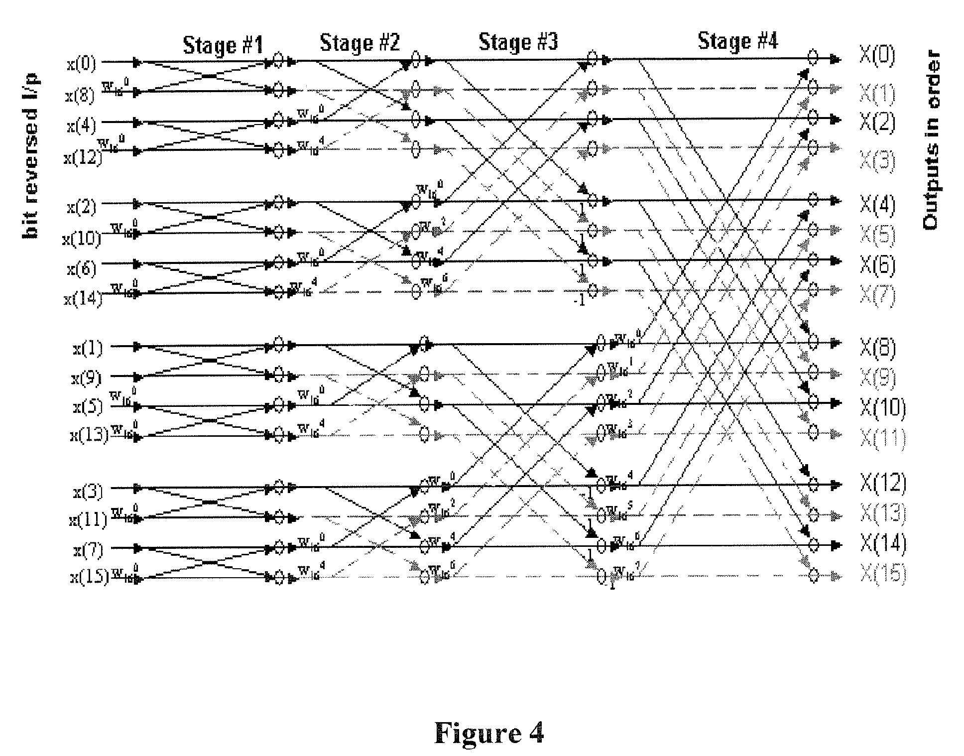
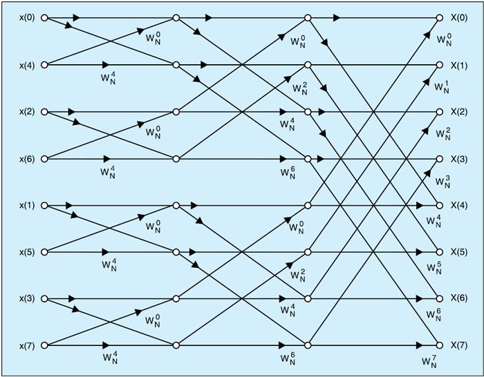
DERIVATION OF THE RADIX-2 FFT ALGORITHM | Chapter Four. The FFT's well-known butterfly pattern of signal flows is certainly evident, and we see the further shuffling of the input data in Figure 4-3. FFT implementation of an 8-point DFT as two 4-point DFTs and four 2-point DFTs. Moving right along, let's go one step further, and then we'll be finished with... PDF Mixed-Signal and DSP Design Techniques, Fast Fourier Transforms The fast fourier transform (FFT) vs. the discrete fourier transform (dft). In the simplified bottom diagram, the multiplications are indicated by placing the multiplier over an arrow, and Fast fourier transforms. The FFTs discussed up to this point are radix-2 FFTs, i.e... Butterfly diagram for 4-point DFT (DIT-FFT) Опубликовано: 2017-05-11 Продолжительность: 12:02 Building of the Butterfly diagram for a 4 point DFT using the Decimation in time FFT algorithm. Reference: The equations are taken from the textbook on Digital Signal Processing by Proakis et al. FFT butterfly input index - Signal Processing Stack Exchange In that diagram of a $16$ point FFT For stage 2: 0 butterflies with 4, 8 butterflies with 12, and so on. Of course stage 2's inputs are stage 1's outputs. My hope is that for each stage of the FFT, I can just have a simple counter going from $0$ to $N-1$ (FFT length $N$), and I can do very inexpensive...
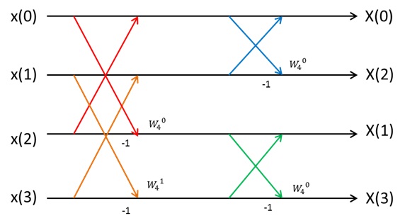
Butterfly diagram for 4-point DFT (DIT-FFT) // WIKI 2 This article is about butterfly diagrams in FFT algorithms; for the sunspot diagrams of the same name, see Solar cycle. This diagram resembles a butterfly (as in the morpho butterfly shown for comparison), hence the name, although in some countries it is also called the hourglass diagram. Butterfly diagram for 4-point DFT (DIT-FFT) - YouTube Building of the Butterfly diagram for a 4 point DFT using the Decimation in time FFT algorithm. Reference: The equations are taken from the textbook on... Figure 8: 4-Point FFT butterfly using Decimation-in-Time. The arrows... Download scientific diagram | 4-Point FFT butterfly using Decimation-in-Time. The arrows indicate a weighting by an appropriate twiddle factor, and the complex addition denoted by the '+'. from The basic 4-point FFT [6] is illustrated in Figure 8 for the decimation-in-time implementation. ... How the FFT works This simple flow diagram is called a butterfly due to its winged appearance. The butterfly is the basic computational element of the FFT, transforming two complex points into two other complex points. Figure 12-7 shows the structure of the entire FFT. The time domain decomposition is accomplished...

The Fourier Transform Part XIV – FFT Algorithm | The Mobile ...
With Fixed Values Slider Range [LJQNRI] You can verify this by viewing the IPD value in the registry found here:Computer\HKEY_USERS\S-1-5-21-830549709-2298230702-1299955731-1001. index: The thumb label's index to format. The smallest value is to the left, the largest to the right. Sets the lower bound of the slider. 23 3⁄16 11 1⁄4 PBQD3 —. Slider Range & Value Arrays.

Computing Inverse DFT (IDFT) using DIF FFT algorithm - IFFT
Design of area and power efficient Radix-4 DIT FFT butterfly unit... In this work, power efficient butterfly unit based FFT architecture is presented. The butterfly unit is designed using floating-point fused arithmetic units. A low power and area efficient pipelined FFT processor using higher radix architecture and folding transformation is presented, which has a simple...
Fast Fourier Transform (FFT)
PDF There are many ways to decompose an FFT | Radix 4, DIT Butterfly 442. FFT Dataflow Diagram. • This is also seen in the FFT in its growth by r times in a radix-r butterfly, and logrN stages in the entire transform: r ^ (logrN) = N. • Thus, the FFT processor requires careful scaling. - Floating point number representation.
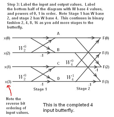
FFT: Constructing a 4 Input Butterfly Diagram
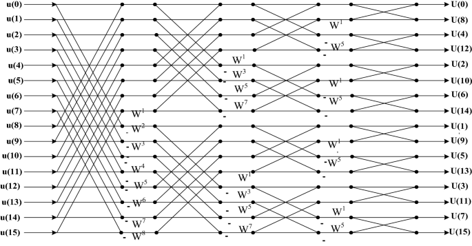
PDF Thesis Figure 2: Butterfly flow diagram for a 16 point FFT. Because of the similarity between the four twiddle factor multiplications necessary to compute a dual-butterfly and a general complex multiplication, a trick to reduce the operation count in the latter computation can also be exploited.

Butterfly diagram - Wikipedia
4 Point Dif Fft Butterfly Diagram This topic is 4 point DIF FFT from the chapter Fast Fourier Transform which has 4 point DIF FFT problems. Building of the Butterfly diagram for a 4 point DFT using the Decimation in time FFT algorithm.

Figure 1 from 64 Point Radix-4 FFT Butterfly Realization ...
PDF A Block Floating Point Implementation for an N-Point FFT on the... Figure 1. Diagram of Fixed-Point Representations − Integer and Fractional. Floating-point arithmetic consists of representing a number by way of two The basic radix-2 butterfly computation in the DIT FFT algorithm is shown in Figure 4 where both the input and twiddle factors are complex values.

radix 4 4-point FFT butterfly diagram | Download Scientific ...
GitHub - akhilwadhwa22/4-and-8-Point-FFT-using-Verilog... Implemented the butterfly diagram of 4-point and 8-point DIT (Discrete in Time) Fast Fourier Transform (FFT) using Verilog.

Length-4, DIT radix-2 FFT | Download Scientific Diagram
Fast fourier transform- butterfly diagrams by virginia menezes A butterfly diagram is a portion of the computation that combines the results of smaller discrete Fourier transforms (DFTs) into a larger DFT, or vice versa (breaking a larger DFT up into subtransforms). Why the Name 'BUTTERFLY'? 4-POINT FFT BUTTERFLY DIAGRAM.
DERIVATION OF THE RADIX-2 FFT ALGORITHM | Chapter Four. The ...
PDF Fig.5.1: Block Diagram of 8 point FFT using 3 stage Butterfly Units In Fast Fourier transform algorithms, a butterfly structure is a part of a calculation that jointly the outcome of compact discrete Fourier transforms (DFTs) during a massive DFT, or conversely (demolition a massive DFT above during sub transforms).
ELEG--305: Digital Signal Processing
FFT: Constructing a 4 Input Butterfly Diagram An FFT is a DFT, but is much faster for calculations. The whole point of the FFT is speed in calculating a DFT. The N Log N savings comes from the fact that there are two multiplies per Butterfly. In the 4 input diagram above, there are 4 butterflies. so, there are a total of 4*2 = 8 multiplies.
Butterfly diagram - Wikipedia
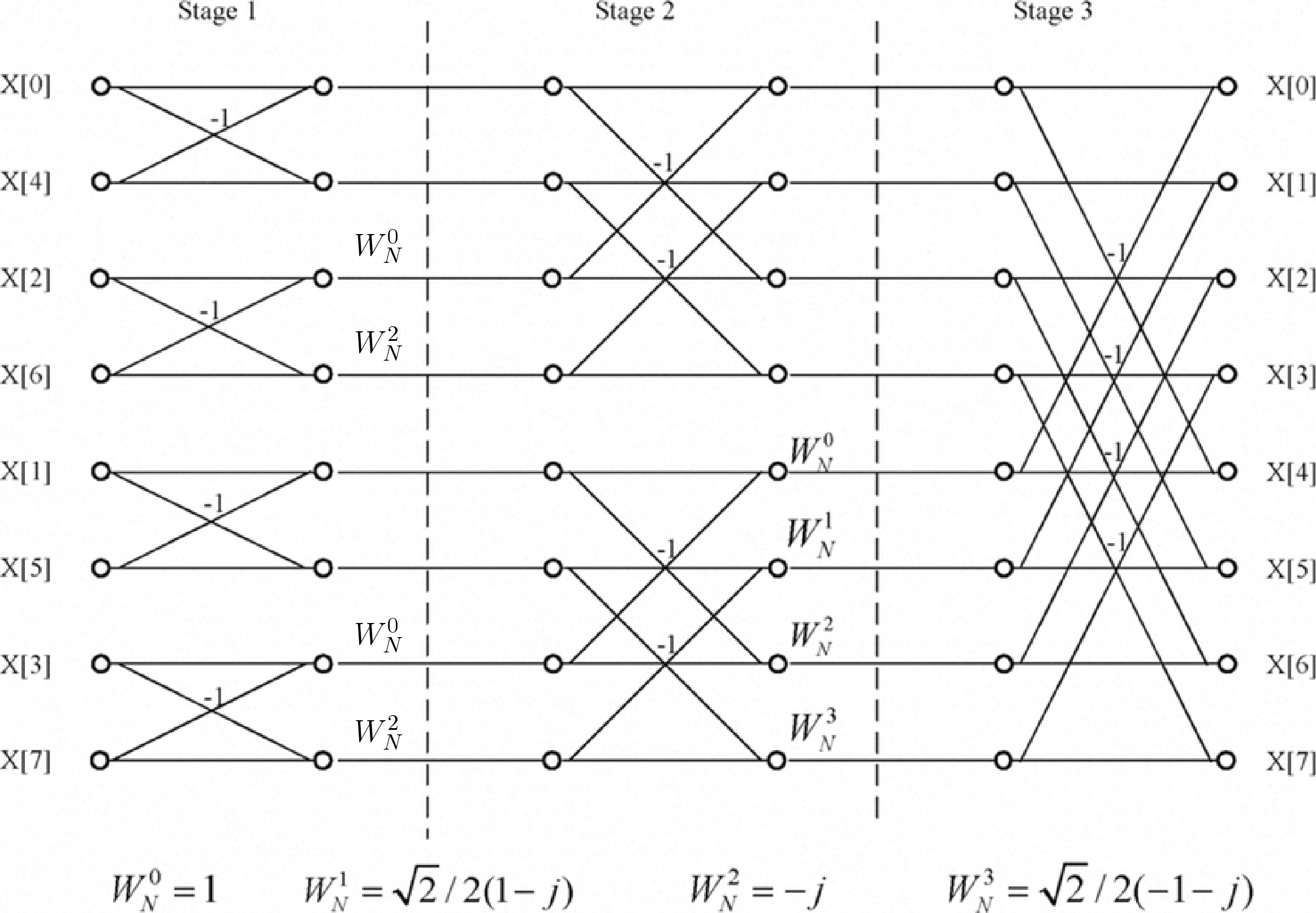
PDF Fast Fourier Transforms The radix-2, DIT FFT Butterfly Kernel on the DSP96002. DSP56156 architectural block diagram. This gives rise to the flow diagram of a DIT fast Fou-rier transform (FFT) as shown in Figure 3-5, which represents a complete 8-point FFT computation.

Figure 3 from FPGA Implementation of 256-Bit, 64-Point DIT ...
Fast Fourier Transform (FFT) Fast Fourier Transform (FFT). In this section we present several methods for computing the DFT efficiently. In view of the importance of the DFT in various digital signal processing applications, such as linear filtering, correlation analysis, and spectrum analysis, its efficient computation is a topic that has...
Fast Fourier Transform (FFT)
High Resolution Single-Chip Radix II FFT Processor for... | IntechOpen FFT processor with burst I/O architecture utilizes Radix II butterfly calculation to execute the arithmetic structure. In spite of Radix IV with burst I/O processor, which the input Figure 11 illustrates the main block diagram of the 1024‐point Radix II floating‐point parallel pipeline (FPP) FFT processor in detail.
Realtime GPGPU FFT Ocean Water Simulation
4 Point Fft Butterfly Diagram - Wiring Site Resource The whole point of the fft is speed in calculating a dft. The radix 4 dif fft divides an n point discrete fourier transform dft into four n...
Fast Fourier Transform. How to implement the Fast Fourier ...
Design FFT circuit | Lib4U | 6-2. Level2: [16,64, 128-point FFT] 1. Purpose The Fourier transform has been widely used in the field of digital signal processing. Figure 4: 4 points FFT circuit block diagram. In figure 3, butterfly processing element that is shown red line make be corresponding to red block in figure 4. Another butterfly processing element is same.
Chapter 4: Fast Fourier Transforms
JAND Download - L&H Scientific Publishing Volume 4 (2015) Volume 3 (2014) Volume 2 (2013) Volume 1 (2012) Journal of Applied Nonlinear Dynamics | | | | ...
Fast Fourier Transform Dr Yvan Petillot FFT Algorithms ...
64 Point Radix-4 FFT Butterfly Realization using FPGA | TechRepublic The Fast Fourier Transform (FFT) and Inverse Fast Fourier Transform (IFFT) play vital role in signal processing. The single butterfly needs 12 complex adders and 3 complex multipliers. The proposed Radix-4 FFT processor is realized on VHDL platform using vertex FPGA.
Computing FFT Twiddle Factors - Rick Lyons
PDF AN2768, Implementation of a 128-Point FFT on the MRC6011 Device The Fast Fourier Transform (FFT) is an efficient way to compute the Discrete-time Fourier Transform (DFT) by exploiting symmetry and periodicity in FFT butterflies are normally performed sequentially. However, the MRC6011 device has 16 processors that can perform 16 simultaneous butterflies.
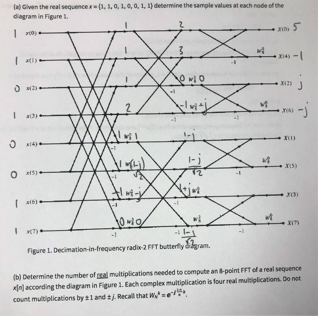
Solved (a) Given the real sequencex f1, 1, 0, 1, 0, 0, 1, 1 ...
Fast Fourier Transform Dr Yvan Petillot FFT Algorithms ...
FFT butterfly input index - Signal Processing Stack Exchange
Solved] Draw the butterfly line diagram for 8-point FFT ...
![wiki:signal_processing:fft [Weber's Wiki]](https://hkn.illinois.edu/wiki/_media/wiki:signal_processing:fft3.png)
wiki:signal_processing:fft [Weber's Wiki]
LSI Design Contest

Decimation-in-time (DIT) Radix-2 FFT - Digital Signal ...

The Fast Fourier Transform (and DCT too…) - ppt video online ...
LECTURE NOTES ON DIGITAL SIGNAL PROCESSING III B.TECH II ...
FPGA Implementation of 8-Point FFT - Digital System Design

Decimation in Frequency FFT (DIFFFT)for N=4
DERIVATION OF THE RADIX-2 FFT ALGORITHM | Chapter Four. The ...

Fast Fourier Transform and C Code Using the Octave GNU Tool
Implementation of Fast Fourier Transform Using C++ ...

The Fourier Transform Part XII – FFT 4 | The Mobile Studio
Implementation of 16-Point Radix-4 FFT Algorithm

4 The basic 4-point DFT building block. | Download Scientific ...
Rethinking the FFT
The Fast Fourier Transform — EG-247 Signals and Systems
An Efficient FPGA Architecture for Reconfigurable FFT ...

The FFT: As a Set of Filter Banks
0 Response to "39 4 point fft butterfly diagram"
Post a Comment