37 open center hydraulic valve diagram
Hydraulic Spool Valve Diagram - Valves Spool Diagram Hydraulic directional spool valve is a relative motion between the valve spool and valve housing, used for controlling fluid-flow direction of actuator motion (movement), select alternative hydraulic oil control circuits, achieve logic control function. The hydraulic spool valves target is to reach different mechanical movement of actuator ... Open and Closed Center Hydraulic Systems - Muncie Power Products Within an open center system, as the pump turns flow is generated and then directed back to the tank through a central passage within the directional control valve. When one of the directional control valve’s spools is stroked, the flow is focused toward a load and pressure is created. Once the pressure exceeds the load, the load moves and the hydraulic work is executed.
L245DT Hydraulic Questions | OrangeTractorTalks ... You do not want a closed center valve, that will blow the pump/ lines every time. You must have an open center valve for it to work. One line off the block (most likely right side of tractor) will be the power in to the FEL valve, then the left side fitting will be the return of fluid to the three point and pressure relief valve.
Open center hydraulic valve diagram
Four-port three-position directional control valve - MATLAB Description. The 4-Way Directional Valve block represents a directional control valve with four ports and three positions, or flow paths. The ports connect to what in a typical model are a hydraulic pump (port P), a storage tank (port T), and a double-acting actuator (ports A and B).Fluid can flow from the pump to the actuator via path P-A or P-B and from the actuator to the tank via path A-T ... Closed Center Conversion - Cross MFG This option provides for conversion from open center to closed center by blocking the open center flow passage with the closed center plug as shown. It may be used in any standard Cross SA or BA valve featuring the conversion plug/power beyond machining in the BYD port. The valve may also be ordered already converted to closed center. US4470260A - Open center load sensing hydraulic system ... The FIGURE is a schematic diagram of an open center, load sensing hydraulic system including a priority-flow control valve. DETAILED DESCRIPTION OF THE PREFERRED EMBODIMENT Referring to the FIGURE, an open center, load sensing hydraulic system 10 is shown which controls the steering of a vehicle, for example, an agricultural or industrial tractor.
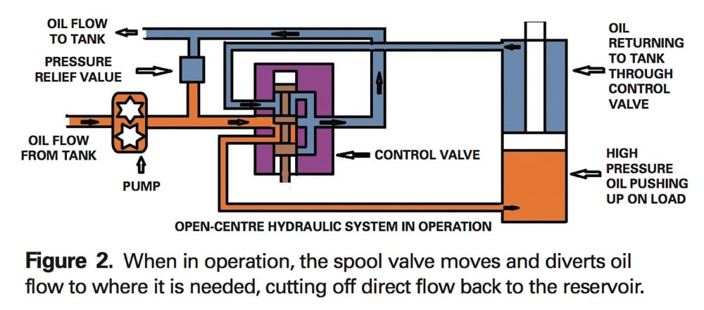
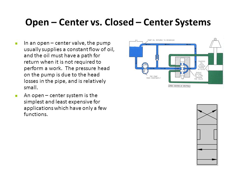
Open center hydraulic valve diagram. GF Central Plastics - GF Piping Systems The complete range of GF Central Plastics products and services supports many applications in the gas, water, and energy sectors. This includes a vast HDPE piping system that contains pipe, conventional fusion, and electrofusion fittings and equipment. Basic Diagrams and Systems - Engineering Library In the preceding chapters, you learned about hydraulic and pneumatic fluids and components of fluid power systems. While having knowledge of system components is essential, it is difficult to understand the interrelationships of these components by simply watching the system operate. The knowledge of system interrelation is required to effectively troubleshoot and maintain a fluid power system. Diagrams provided in applicable technical publications or drawings are a valuable aid in understanding the operation of the system and in diagnosing the causes of malfunctions. This chapter explains the different types of diagrams used to illustrate fluid power circuits, including some of the symbols that depict fluid power components. Included in this chapter are descriptions and illustrations denoting the differences between open-center and closed-center fluid power systems. The last part of the chapter describes and illustrates some applications of basic fluid power systems. Hydraulic System on 4230 - TractorByNet look here. jd432 hydraulic system diagram - Google Search more info. " Summary The Power Beyond hydraulic system is used as a pressure/flow source for additional functions equipped with independent flow control valves. For example, planter vacuum motors, spray pumps, lift cylinders. Use Power-Beyond when: Tractor SCV control is not needed. Implement control valve requires external load sense ... Basic Hydraulic Open Center System Schematic Basic Hydraulic Open Center System Schematic. Hydraulic and Pneumatic Knowledge Fluid Power Equipment. Basic Hydraulic Open Center System Schematic. Open-Center System. In this system, a control-valve spool must be open in the center to allow pump flow to pass through the valve and return to the reservoir.
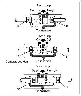
Intro to Directional Control Valves - LunchBox Sessions Positions. Most directional control valves are of a spool-type construction. The spool has lands and undercuts, housed within precision-machined casing. As the spool shifts, the lands and undercuts open and close flow paths. The example valve has 3 positions: center, straight through (P to A), and crossover (P to B). What is the difference between closed center and open ... Answer (1 of 7): Open Center refers to the open central path of the control valve, when valve is in neutral position. The hydraulic pump is continuous flow type. When valve is neutral then hydraulic fuid goes back to reservoir. As we move valve to (lets say extend actuator side) hydraulic path di... The Best Way to Read a Hydraulic Schematic - Mentored Engineer Avoid Using Tandem Center Valves in Series. Connecting Multiple Open Center Valves Using Power Beyond. Directional Control Valves – What Every Engineer Should Know. A Quick Guide to the Basics of Hydraulic Relief Valves and Filters. Valve Actuation. All positional valves need to be actuated to perform a function. We will start with mechanical ... Introduction to Valve Symbol Reading - LunchBox Sessions Hydraulic valves have a tendency to be the most complex components of a hydraulic system, and their schematic symbols are just as complex. ... A 4 port, 3 position, pilot operated, spring returned, open center valve A relief valve A 3 port, 2 position, pilot operated, spring returned valve A 3 port, 2 position, solenoid operated, spring ...
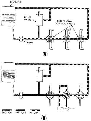
PDF Directional Control Valve Equipment for Front End Loaders The CV432 open center valve is a parallel circuit valve which is designed to operate in open center hydraulic systems up to pressures of 320 bar (4600 psi) and flow rates of up to 80 l/min (21 USG pm). The LS version of the CV432 is designed to operate with a Basic Hydraulic Open Center Series Connection System Schematic Hydraulic and Pneumatic Knowledge Fluid Power Equipment. Basic Hydraulic Open Center Series Connection System Schematic. Illustrated below, shows an open-center system with a series connection. Oil from a pump is routed to the three control valves in series. The return from the first valve is routed to the inlet of the second, and so on. Open and Closed Circuit Hydraulic Pump Systems 101 An open loop circuit is where the inlet to the hydraulic pump and the return flow on the hydraulic motor or actuator are connected to the hydraulic fluid reservoir. The system can include relief and other control valves that direct fluid to the actuators and then back into the reservoir. Open-center selector valve | Article about open-center ... A type of hydraulic selector valve used in an open-center hydraulic system that allows hydraulic fluid to flow from the pump to the reservoir when the selector valve is placed in neutral (i.e., when none of the actuating cylinders are receiving fluid under pressure). See open-center hydraulic system.
Understanding hydraulic systems - Grainews
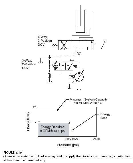
PDF C. Signature 12 - your mobile hydraulics source The most common type of hydraulic circuit is the par- allel circuit. Refer to the parallel circuit diagram. With all valve spools centered, the pump flow will return to tank at low pressure through the open center bypass. When a spool is actuated, the open center bypass is blocked and the inlet is connected to one of the work ports.

Open & Closed Center Systems | LunchBox Sessions
How to Connect Multiple Valves Using Power Beyond ... Open center or through center valves need to be connected in series using power beyond porting. Power Beyond allows unused flow to power multiple valve sets downstream. Power beyond also allows the designer to choose which valve sections are more important than another.
Steering Unit – Bosch Rexroth AG
PDF LS DIRECTIONAL CONTROL VALVES ... - Brand Hydraulics Co. Hydraulic Kick-out Adjustment - The SH & SHA models have an adjustable single hydraulic kick out preset to 800-1000 psi. The HHA model comes equipped with a double hydraulic kick out preset to 800-1000 psi. To adjust kick-out pressure: Locate jam nut, and set screw on the spool action cap. (Opposite valve's handle)

Open-center valves in mobile equipment - Part 2 | Power & Motion
How to configure mobile hydraulic valves using power beyond Figure 2. Connection of an additional open center DCV using the power beyond facility. Most mobile directional control valves can be made closed center by plugging the drilling between the pressure and tank galleries and leaving the power beyond port plugged (Figure 3). This means that if the existing valve is closed center, supplying pump flow ...

SDCF Series 1-Spool Monoblock Valve With Pressure Comp. Flow Control, 4-way 3-position, Open Center Friction Detent Spool, 0-12 GPM Flow Range
Valve Symbols | Tameson.com A 2/2 valve has two states (open/close) and is therefore represented by two adjacent squares. In each square is shown how the medium can flow between the ports. This is done with arrows, that indicate which ports are connected and what is the flow direction. Closed ports are indicated by a 'T'. To indicate which square is active when the solenoid is electrically energized, a little …
Closed Center Versus Open Center Hydraulics | Brendan Casey's ...
Orbital Valves - Orbital Valve Information - Hydraulic ... Orbital Valve Information. Steering unit designs / options. The type of steering unit of greatest interest to Off-Road Vehicles is the Open Center / Non Load Reaction. It is the simplest and most economical design, has all the features we typically need, and uses a fixed displacement pump. Non-Load Reaction.

Ospc-160 Open Center Hydraulic Steering Unit - China ...
Directional Control Valves | Hydraulic Valves - Surplus Center 1 Spool 10 GPM Chief 220906 DA Hydraulic Valve. Item Number: 9-12460 648 In Stock. Qty: $69.95. Quick View.
What is the use of a float centred 4/3 solenoid valve, and is ...
Hydraulics Systems Diagrams and Formulas - Cross MFG Winch. The diagram shows a winch powered by a hydraulic motor. The directional control valve with built-in relief features optional flow control to control the speed of the winch . The hydraulic pump and motor must be matched to the torque requirements of the winch.

Hydraulic machinery - Wikipedia
Instrumentation Abbreviations Table - Engineering Units Car Seal Open: CV: Control Valve – E – – E – E/I: EMF to Current Converter: ES: Electrical Switch: ESD: Emergency Shutdown Station: ESDV: Emergency Shutdown Valve – F – – F – FAL: Flow Alarm Low: FAH: Flow Alarm High: FAHH: Flow Alarm High For Level Above FAH: FAHL: Flow Alarm [High/Low] FALL: Flow Alarm Low For Level Below FAL: FC: Flow Controller: FC: …
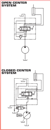
Open and Closed Center Hydraulic Systems
Open-center valves in mobile equipment - Part 2 | Power ... The analytical schematic for the full series, open-center valve under current discussion is shown in Figures 2 and 3. Figure 3. Analytical schematic shows spool of the first valve partially shifted in opposite direction to open flow path from the valve's P port to A port.

OVERCENTER VALVE FOR MOTORS MP-MR (OMP-OMR) DOUBLE ACTING ...
Basics of Directional-Control Valves | Power & Motion The valves in Fig. 3 are arranged to match the closed-center spool condition of the valve in Fig. 2. An open-center condition (Fig. 4), could be achieved simply by making all the binary valves normally open (NO) instead of normally closed. Likewise, tandem- and float-center configurations can be accomplished by using NO and NC binary valves.
完整PPT讲解 – 各种液压阀的工作原理与计算选择 | 静液压
open center valve - YouTube video explains the working principles of an open center spool valve.

OVERCENTER VALVE DOUBLE ACTING VBCD/A DE-FLV TYPE - Contarini
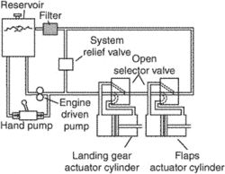
Aircraft Basic Hydraulic Systems and Hydraulic Power Systems An open center system is one having fluid flow, but no pressure in the system when the actuating mechanisms are idle. The pump circulates the fluid from the reservoir, through the selector valves, and back to the reservoir. [Figure 2] The open center system may employ any number of subsystems, with a selector valve for each subsystem.
Hydraulic/pneumatic power systems
How to Read P&ID Component & Valve Symbols [w/ Download] A piping and instrumentation diagram (P&ID) includes symbols for ball valves, communication lines, vessels and other components. Here’s how to read a P&ID. Skip to content. Search… Search. Sales: 603-244-7931 Company. Login; Selections 0; Series. Featured; Legacy; Performance Automation Series. Ideal for OEM and end-user automated valve applications …
Hydraulic Closed-Center Circuit with Load Sensing - Hydraulic ...
How to Convert 3-Function Loader Control Valve to Open ... This 3-function loader control valve (with float) is designed to work with 10 to 80 HP tractors without a cab, that have a front end loader with a grapple. L...

Hydraulic Open-Center System - Hydraulic & Process Valve
Hydraulic Solenoid Valve - How They Work | Tameson.com A hydraulic solenoid valve is a solenoid controlled directional valve used in a hydraulic system for opening, closing or changing the direction of flow of the liquid. The valve operates with a solenoid, which is an electric coil wound around a ferromagnetic core at its center. The valve consists of various chambers also called ports. The solenoid is used for sliding the spool …

Mechanical Hydraulic Basics Course, Lesson 23,Directional Control - Open Vs Closed Center
US4470260A - Open center load sensing hydraulic system ... The FIGURE is a schematic diagram of an open center, load sensing hydraulic system including a priority-flow control valve. DETAILED DESCRIPTION OF THE PREFERRED EMBODIMENT Referring to the FIGURE, an open center, load sensing hydraulic system 10 is shown which controls the steering of a vehicle, for example, an agricultural or industrial tractor.
✓ Solved: In an open-center hydraulic circuit, which of the ...
Closed Center Conversion - Cross MFG This option provides for conversion from open center to closed center by blocking the open center flow passage with the closed center plug as shown. It may be used in any standard Cross SA or BA valve featuring the conversion plug/power beyond machining in the BYD port. The valve may also be ordered already converted to closed center.

Basic Hydraulic Open Center Series Parallel Connection System ...
Four-port three-position directional control valve - MATLAB Description. The 4-Way Directional Valve block represents a directional control valve with four ports and three positions, or flow paths. The ports connect to what in a typical model are a hydraulic pump (port P), a storage tank (port T), and a double-acting actuator (ports A and B).Fluid can flow from the pump to the actuator via path P-A or P-B and from the actuator to the tank via path A-T ...

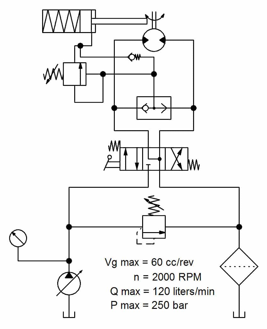
Hydraulic schematic of Steering Control Unit (Danfoss [9 ...
Open Center Sliding Spool Directional Control Valve ...

Hydraulic Closed Center System – Hydraulic Schematic ...

Hydraulic Four-Way Valves - CAT Hydraulic Troubleshooting
Hydraulic Symbology 201 – industrial directional valves
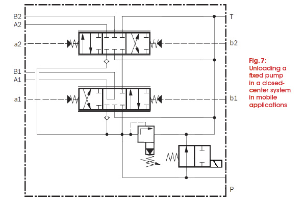
Energy-Saving Considerations and Fixed Pump Unloading - Fluid ...

Four-port three-position directional control valve - MATLAB
Open-center hydraulic system | Article about open-center ...

How to configure mobile hydraulic valves using power beyond
Hydraulic Servo Systems : Dynamic Properties and Control
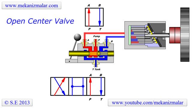
Open Center Valve

OVERCENTER VALVE DOUBLE ACTING VBCD/A DE TYPE - Contarini

Open-center valves in mobile equipment | Power & Motion

Aircraft Basic Hydraulic Systems and Hydraulic Power Systems

Hydraulic Closed-Center System - Hydraulic Repair Schematic
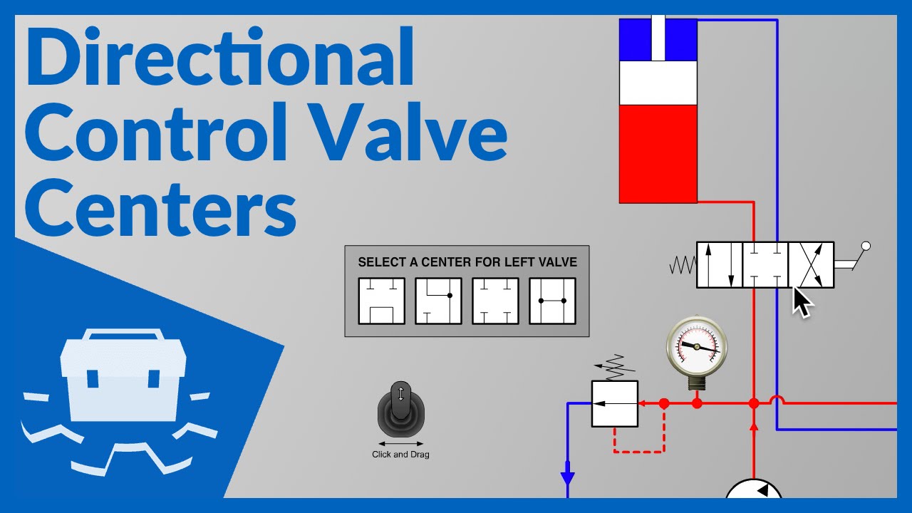
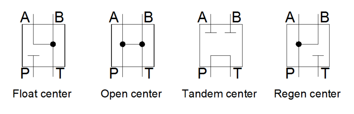
Directional Control Valve Centers

Four-way Open-center Hydraulic Valve – Hydraulic Schematic ...
Circuit to provide position control for double action ...
0 Response to "37 open center hydraulic valve diagram"
Post a Comment