37 mohr's three circle diagram
Some applications of the Mohr diagram for three ... The Mohr diagram for strain is rarely used in its full form, as a representation of three-dimensional strain. Recent attention has focused on various uses of the Mohr circle to express two-dimensional strain tensors. This contribution redescribes the Mohr diagram for three-dimensional strain and illustrates some new applications. Solved: For each of the plane stress states listed ... - Chegg Solutions for Chapter 3 Problem 15P: For each of the plane stress states listed below, draw a Mohr's circle diagram properly labeled, find the principal normal and shear stresses, and determine the angle from the x axis to σ1. Draw stress elements as in Fig. 3-1 lc and d and label all details.(a) σx = 20kpsi, σy = - 10kpsi, τxy = 8 kpsi cw(b) σx = 16kpsi, σy = 9kpsi, τxy = 5kpsi ccw ...
PDF Lecture 6 Mohr's Circle for Plane Stress which is the equation for a circle with centre (σ avg,0) and radius R. This circle is usually referred to as Mohr's circle, after the German civil engineer Otto Mohr (1835-1918). He developed the graphical technique for drawing the circle in 1882. The construction of Mohr's circle is one of the few graphical techniques still used in ...

Mohr's three circle diagram
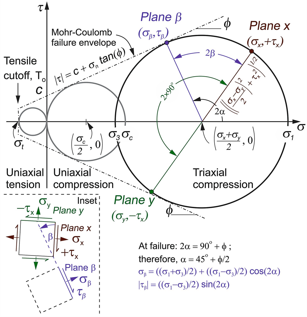
How To Construct A Mohr's Circle - Blog Stress Analysis With The Mohr's Circle: 7. Stress Analysis on Mohr's circle - To get normal and shear stress values at any plane theta, take angle 2φ in the Mohr's circle starting from diagonal of the circle and locate a peripheral point as as shown. Shear stress value will be on the y-axis and normal stress values will be on the x-axis. Mohr's circle in 3 dimensions | pantelisliolios.com In the general 3 dimensional case, for a given state of stress at a point, the Mohr circle diagram has three circles as shown in Fig. 1. Mohr's circle diagram is used frequently in conjunction with failure criteria like the Mohr-Coulomb failure criterion. Figure 1: In the three dimensional case there are three Mohr's circles. For each of the plane stress states listed below ... - YouTube Check out some Engineering Merchandise in our Store: you !!!For each of the plane stress s...
Mohr's three circle diagram. How to Draw a Mohr's Circle: 7 Steps (with Pictures ... Mark the points where the Mohr's Circle cuts the horizontal axis as G and H respectively (G being the farthest point on the axis and H the nearer or negative cutting point). 7. To find the values of the stress on a plane at any angle from the axis of the force, draw a radius CP at twice that angle, the angle being measured from the radius CE. ... Mohr's Circle Calculator - MechaniCalc The Mohr's Circle calculator provides an intuitive way of visualizing the state of stress at a point in a loaded material. See the reference section for details on the methodology and the equations used. Cannot display plot -- browser is out of date. Since the normal stresses on the element are equal and the shear stress is zero, the stresses ... PDF Mohr's Circle - Illinois Institute of Technology Mohr's Circle Equation •The circle with that equation is called a Mohr's Circle, named after the German Civil Engineer Otto Mohr. He also developed the graphical technique for drawing the circle in 1882. • The graphical method is a simple & clear approach to an otherwise complicated analysis. 3D Mohr's Circle - YouTube This video is about 3D Mohr's Circle
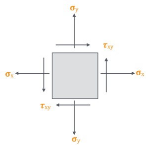
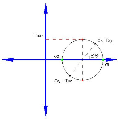
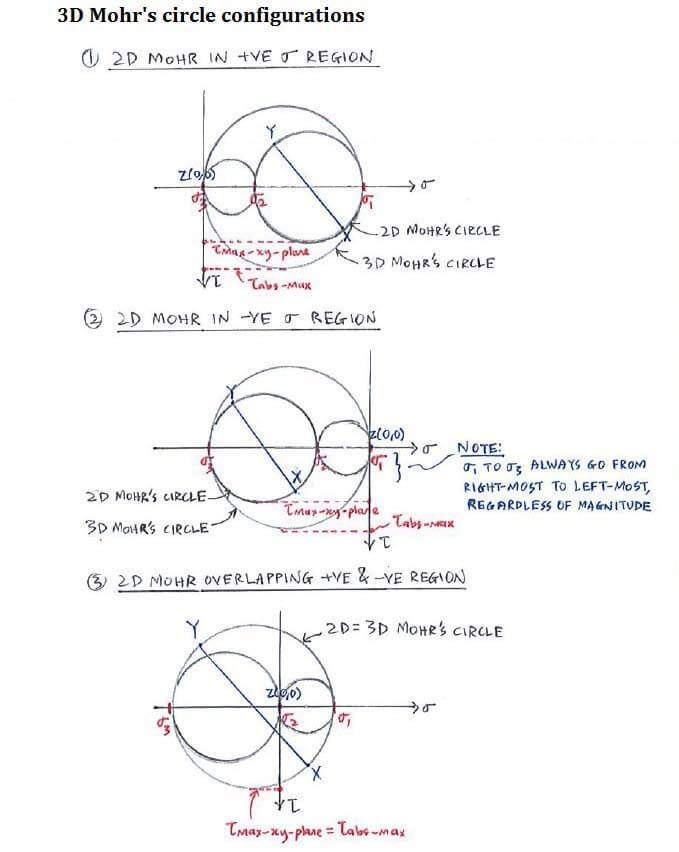
Mohr's Circle for Stress-Strain - Equations, 2D, Examples ... Mohr's circle is the graphical representation of the transformation law for Cauchy stress tensor. Mohr's Circle for 2D Stress In a two-dimensional state, three stress components namely - Normal stresses σx and σy and Shear stress τ xy give the stress tensor at any given point O. Fig. 3 Mohr's circle for 2D stress PDF Mohr's Circle in 3-D - Mercer University In plotting Mohr's circles for three-dimensional stress, the principal normal stresses are ordered so that -2 Œ3. Then the result appears as in Fig. 3—12a. The stress coordinates U, T for any arbitrarily located plane will always lie on the boundaries or within the shaded area. › 1000-engineering-mechanics1000 Engineering Mechanics MCQ (Multiple Choice ... - Sanfoundry Explanation: The three force theorem states that when three forces occur on a body, the force systems are in equilibrium, coplanar, and either concurrent or parallel. 8. Which of the following is the SI unit of force? PDF Mohrs Circle - MIT Step 3 • Begin the construction by doing the following: 1.Plot σ 11, - σ 12 as point A 2.Plot σ 22, σ 21 as point B 3.Connect A and B • Then complete the circle by doing Step 4: 4.Draw a circle of diameter of the line AB about the point where the line AB crosses the horizontal axis (denote this as point C) Extensional Step 4
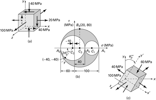
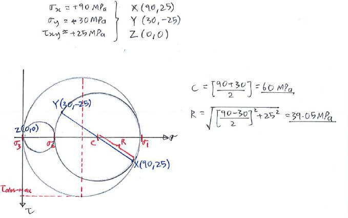
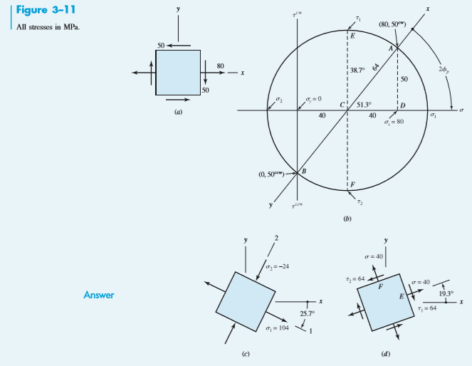
Mohr 3D circle calculator - Granit Eng See all the new course in 2021. Mohr circle calculation for a 3D stress. Use : Insert data related to the stress condition. Return of the distinctive values. Graphical visualization of Mohr circle. STRESS TENSOR DEFINITION. Solved: For each of the stress states listed below ... - Chegg Draw a complete Mohr's three-circle diagram and label all points of interest. ( a) σx = -80MPa, σy = -30MPa, τxy = 20MPa cw ( b) σx = 30MPa, σy = -60MPa, τxy = 30MPa cw ( c) σx = 40MPa, σz = -30MPa, τxy = 20MPa ccw ( d) σx = 50MPa, σz = -20MPa, τxy = 30MPa cw Step-by-step solution 98% (88 ratings) for this solution Step 1 of 5 a) Mohr's Circle on the App Store Mohr's Circle Graphs 4 Views Including: Mohr's Circle Diagram. Stress State Rotated to the Principal Stress Plane. Stress State Rotated to the Max Shear Stress Plane. Stress State Rotated to an arbitrary angle. Mohr's Circle Features: Universal App (Designed for both the iPhone and iPad) Share your results via a printout or email. The Mohr Circle The Mohr Circle Geologists and engineers calculate normal and shear stresses from the orientation and magnitude of two of the three principal stresses using the Mohr diagram. This diagram graphically illustrates in two dimensions the complex mathematical relationships between the components that make
Draw the three Mohr's circles that describe each of the ...
PDF Brannon Mohr's Circle and more circles Those who already know Mohr's circle may recall that an angle gets dou-bled when portrayed in Mohr's circle , which can be very confusing. Section 2 introduces a little known enhancement to Mohr's circle (namely, the Pole Po int) that rectifies this prob - lem. Some engineering applications of the 2D Mohr's circle are provided. Figure 1.1.

Mohr circle for strain. | Download Scientific Diagram
Mohr's Circles for 3-D Stress Analysis - Virginia Tech Mohr's Circles for 3-D Stress Analysis The 3-D stresses, so called spatial stress problem, are usually given by the six stress components s x , s y , s z , t xy , t yz , and t zx , (see Fig. 3) which consist in a three-by-three symmetric matrix (stress tensor): (16)
How To Construct A Mohr's Circle - Blog
Mohr's Circle - StructNotes Intro and Derivation Mohr's circle is a geometric representation of plane (2D) stress transformation and allows us to quickly visualize how the normal (σ) and shear (τ) stress components change as their plane changes orientation. German civil engineer Otto Mohr developed this method from the good ol' stress transformation equations.

RoyMech - Mohr's Circle
Rehydration: Diagram Mohr - Blogger Mohr's Circle In the equations that we derived for Mohr's circle, we measured the angle, q, as the angle between s1 and the normal to the fault plane. On the Mohr diagram, q is represented by measuring 2 q counter clockwise from the maximum normal stress, s1. In general, q will be approximately 60° so that the cos 2 q will be a negative number.

PDF) 3D Mohr diagram to explain reactivation of pre-existing ...
Mohr's Circle Calculator for Plane Stress and Plane Strain ... Mohr's circle is an easy way of visualizing the state of stress at a point in a loaded material. This calculator is currently in BETA testing mode. Currently only 2D Plane Stress is available, however 2D Plane Strain and 3D Plane Stress/Strain will be added later.

Using Mohr's Circle for Plane Strain - Vortarus Technologies LLC
en.wikipedia.org › wiki › Fracture_(geology)Fracture (geology) - Wikipedia The Mohr's Diagram shown, provides a visual example. For a given stress state in the earth, if an existing fault or crack exists orientated anywhere from −α/4 to +α/4, this fault will slip before the strength of the rock is reached and a new fault is formed.

Mohr circle diagram with the Mohr-Coulomb-Griffith failure ...
Mohr's circle - Wikipedia Mohr's circle is a two-dimensional graphical representation of the transformation law for the Cauchy stress tensor.. Mohr's circle is often used in calculations relating to mechanical engineering for materials' strength, geotechnical engineering for strength of soils, and structural engineering for strength of built structures. It is also used for calculating stresses in many planes by ...
1.15 Mohr's Circles in Three Dimensions | Advanced Mechanics ...
Mohr's circle explained | How to draw mohr's circle? Mohr's circle represents the graphical form of the transformation law. The mohr's circle is the easiest method for finding the principal stresses and normal stresses at various planes. Each point on the circumference of mohr's circle represents a certain plane which gives the value of normal stress and shear stress at that plane.

Mohr's Circle for 3D Stress Analysis
PDF Mohr's Circle for Plane Stress - University of Arizona Construct Mohr's circle as follows: 1. Determine the point on the body in which the principal stresses are to be determined. 2. Treating the load cases independently and calculated the stresses for the point chosen. 3. Choose a set of x-y reference axes and draw a square element centered on the axes. 4. Identify the stresses σ x, σ y, and ...

For each of the stress states listed below, find all three p ...
› calculatorsOnline Engineering Calculators, formulas and Tools Free ... Sprocket Pitch Diameter Formulas and Calculator The sprocket pitch diameter is an imaginary circle through which the chain pin centers move around the sprocket. Chain Length For Two Sprockets Formulas and Calculator It is sometimes necessary to fix the center-to-center distance of the sprockets to accommodate existing constraints or mechanical ...
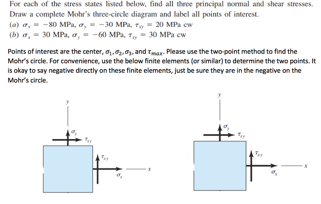
Solved For each of the stress states listed below, find all ...
en.wikipedia.org › wiki › Mohr–Coulomb_theoryMohr–Coulomb theory - Wikipedia Mohr's circle is used to determine which principal stresses will produce this combination of shear and normal stress, and the angle of the plane in which this will occur. According to the principle of normality the stress introduced at failure will be perpendicular to the line describing the fracture condition.

3D Mohr's Circle - File Exchange - MATLAB Central
Lecture 5: Mohr's Circle Summary Example - CosmoLearning This video shows a comprehensive workout on an example of Mohr's circle representing that how much rotation required for an element to reach at principle stresses conditions. Very first, the video gives an overview on the schematic diagram of a rectangular block section that experiences normal & shear stresses of certain values.

2D Mohr's Circle - File Exchange - MATLAB Central
Mohr's Circle Diagram Creation Calculation Example Mohr's circle is an important tool used for visualizing relations between normal stresses, maximum principal stresses, shear stresses and maximum shear stresses. Mohr circle diagram was developed by Christian Otto Mohr and it is used widely even now. We will see how to create a Mohr's circle if normal stresses and shear stresses are given.
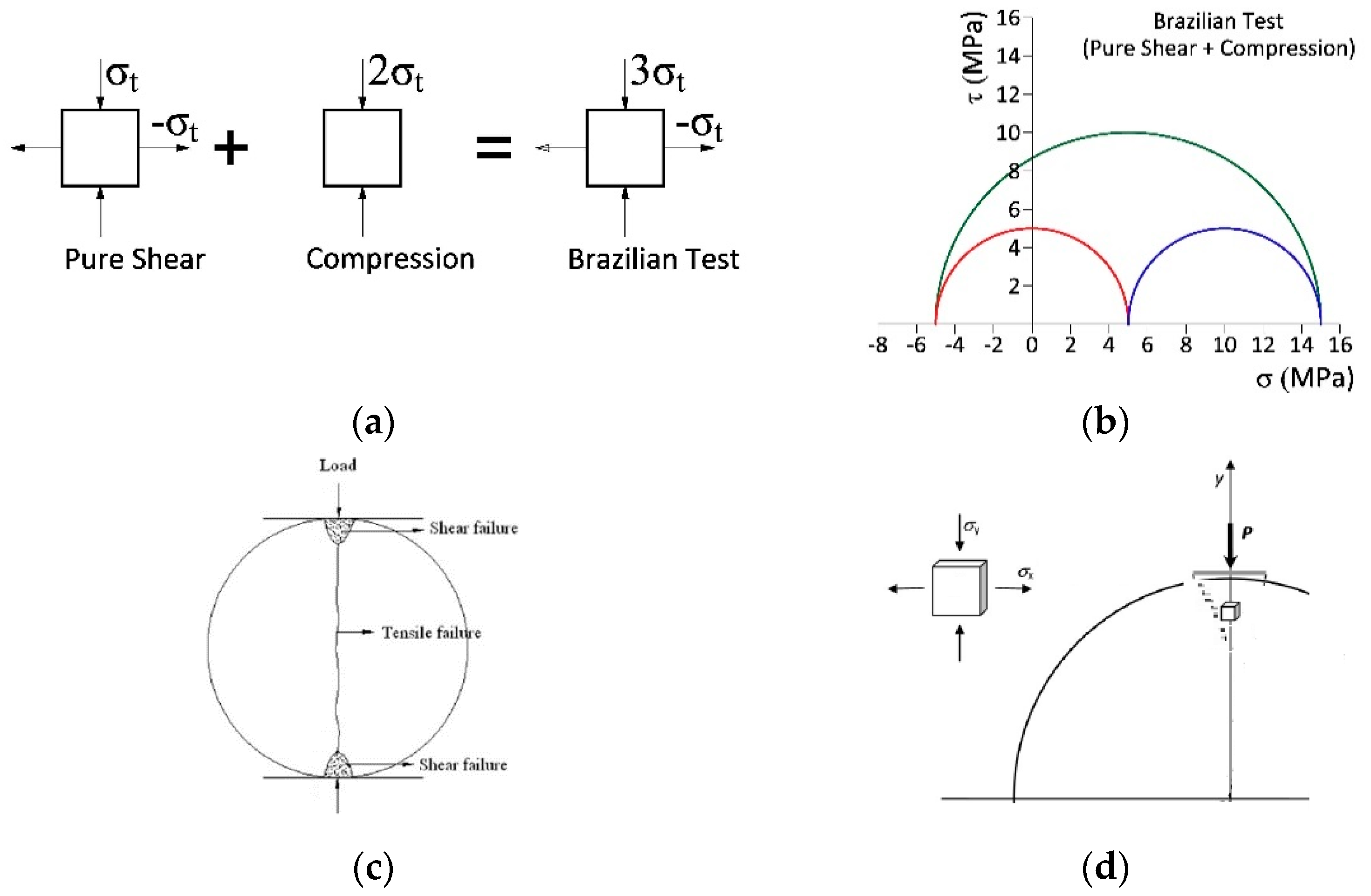
Crystals | Free Full-Text | Determination of Mohr-Coulomb ...
For each of the stress states listed below, find all three ... Draw a complete Mohr's three-circle diagram and label all points of interest. (a) \sigma_ {x}=-80 \mathrm {MPa}, \sigma_ {y}=-30 \mathrm {MPa}, \tau_ {x y}=20 \mathrm {MPa} \mathrm {cw} σx = −80MPa,σy = −30MPa,τ xy = 20MPacw (b) \sigma_ {x}=30 \mathrm {MPa}, \sigma_ {y}=-60 \mathrm {MPa}, \tau_ {x y}=30 \mathrm {MPa} \mathrm {cw} σx = 30MPa,σy

Mohr Circle Diagram Illustrating Envelope of Failure. The ...
Mohr's Circle - Roy Mech There are always three principal stresses - (though one of the principal stress may be zero). typical three dimensional mohr's circle diagrams are shown below.. Theory The following Trigometric relationships apply. Cos θ2=(1 + Cos (2θ) ) /2 Sin θ2=(1 - Cos (2θ) ) /2 Sin θCos θ= Sin (2θ) /2 Analysing the resulting stresses when rotating the axes
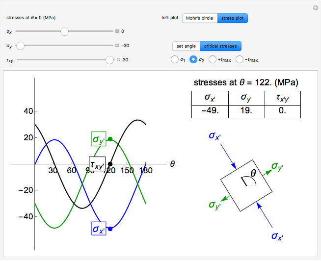
Mohr's Circle and Stress Transformations - Wolfram ...
For each of the plane stress states listed below ... - YouTube Check out some Engineering Merchandise in our Store: you !!!For each of the plane stress s...
Construction of a 3D Mohr diagram. Three families of ...
Mohr's circle in 3 dimensions | pantelisliolios.com In the general 3 dimensional case, for a given state of stress at a point, the Mohr circle diagram has three circles as shown in Fig. 1. Mohr's circle diagram is used frequently in conjunction with failure criteria like the Mohr-Coulomb failure criterion. Figure 1: In the three dimensional case there are three Mohr's circles.
Mohr's Circles for 3-D Stress Analysis
How To Construct A Mohr's Circle - Blog Stress Analysis With The Mohr's Circle: 7. Stress Analysis on Mohr's circle - To get normal and shear stress values at any plane theta, take angle 2φ in the Mohr's circle starting from diagonal of the circle and locate a peripheral point as as shown. Shear stress value will be on the y-axis and normal stress values will be on the x-axis.
Example | C7.4 3D Mohr's Circle and Abs. Max Shear Stress ...

Mohr's circle for the three-dimensional shear stress tensor ...
Mohr's Circle Diagram Creation Calculation Example

Mohr Circle Diagram Illustrating Envelope of Failure. The ...
Mohr's Circle and Stress Transformations - Wolfram ...
Mohr's Circle in 3-D
Mohr's Circle and Stress Transformations - Wolfram ...

Mohr circle representation of in situ effective stress ...
Solved (2D Mohr's circle) For each of the plane stress ...

Mohr Circles schematically showing the variation of effective ...

Mohr's circle - Wikipedia
Mohr Circle | SpringerLink

(32C) Example - Mohr's circle 3D

Draw Mohr's Circle using Excel Scatter chart – excelexplorer

Why Mohr-circle analyses may underestimate the risk of fault ...

For each of the stress states listed below, find all three p ...
Mohr's Circle in 3-D

Mohr's circle - Wikipedia
Example | C7.4 3D Mohr's Circle and Abs. Max Shear Stress ...
0 Response to "37 mohr's three circle diagram"
Post a Comment