37 timer relay wiring diagram
Having a map of your home's electrical circuits can help you identify the source of a problem. ADAMElectrical wiring. P3: Relay will turn ON for time OP after getting a trigger signal and then turn relay OFF.Module will reset and stop timing if it gets a trigger signal again during delay time OP. P4: Relay will turn OFF for time CL after getting a trigger sighal and then relay will turn ON for time OP.Relay will turn OFF after finish timing.
8 Pin Timer Relay Wiring Diagram | Basic Timer Connection And Function |Three Phase Main Distribution Board Wiring | 3 Phase Distribution MDB Box Wiring Diag...

Timer relay wiring diagram
Regardless of the type of time relay, as long as the timing time is equal to the set time, its output contacts will act to achieve the purpose of the timing control circuit. 4) For DC products, pay attention to wiring according to the circuit diagram and pay attention to the polarity of the power supply. 11 Pin Timer Relay Wiring Diagram. Author: Ryan Published Date: December 13, 2021 Comments: Leave a Comment on 11 Pin Timer Relay Wiring Diagram. Delay Timer With Push Button Timer Electrical Circuit Diagram 3 Way Switch Wiring. Star Delta Starter Wiring Diagram 3 Phase With Timer Electrical Online 4u Circuit Diagram Electrical Circuit Diagram ... 17 May 2021 — Here, you can see the terminal diagram of on delay timer in the below figure. ... Here, you can see total of eight terminals is there. A1 and A2 ...
Timer relay wiring diagram. The diagram above is the 5 pin relay wiring diagram. There are different kinds of relays for different purposes. It can be used for various switching. Relay can be the best option to control electrical devices automatically. 5 pin is compromised of 3 main pins and an SPDT (single pole double throw). 8 pin timer relay wiring diagram The electric timer allows a light point to be turned on from one or more places in the room, and to leave this light point on for an adjustable period of time. The control points are pushbuttons with indicator lights (in order to be able to locate them in the event of extinction). voltage, the time relay (t) Upon application of input begins. At the end of the time delay (t), the output is energized. Input voltage must be removed to reset the time delay relay & de-energize the output. The timer function #1 is ON DELAY, it allows to supply power after a period of time (t). There are two Timer’s wiring diagram ..... 5 2.1 Connecting 5amp timer ... During the circuit design with the timer relay and variety of timer configuration, questions such as
How To Wire Pin Timers – 8 Pin Relay Wiring Diagram. Wiring Diagram comes with several easy to stick to Wiring Diagram Directions. It is intended to aid all the common consumer in creating a proper system. These instructions will likely be easy to grasp and use. With this particular guide, you may be able to see how each and every component ... wire on Terminal 1, (See Diagram A). WIRING The # 950-1067 Timer/Relay may be used to replace either the 24 VAC input # 950-1060 or the 120 VAC input # 950-1065 Timer/Relays. The # 950-1067 is designed to accept either 24 VAC or 120 VAC control input signals on terminals 4 & 5. The control inputs are non-polarity sensitive. Install jumper wire between 7 and 8 to put 120V to timer relay. ... Why the 3-way switch diagram works... because the switch is ON full time. When the timer ... 17 May 2021 — Here, you can see the terminal diagram of on delay timer in the below figure. ... Here, you can see total of eight terminals is there. A1 and A2 ...
11 Pin Timer Relay Wiring Diagram. Author: Ryan Published Date: December 13, 2021 Comments: Leave a Comment on 11 Pin Timer Relay Wiring Diagram. Delay Timer With Push Button Timer Electrical Circuit Diagram 3 Way Switch Wiring. Star Delta Starter Wiring Diagram 3 Phase With Timer Electrical Online 4u Circuit Diagram Electrical Circuit Diagram ... Regardless of the type of time relay, as long as the timing time is equal to the set time, its output contacts will act to achieve the purpose of the timing control circuit. 4) For DC products, pay attention to wiring according to the circuit diagram and pay attention to the polarity of the power supply.

condenser fan motor not work | IH8MUD Forum

Wiring Diagram Of Timer Relay - RIAHSOSHI

Get Dayton Time Delay Relay Wiring Diagram Download

Wiring Diagram: 28 Solid State Timer Wiring Diagram

Get Dayton Time Delay Relay Wiring Diagram Download

Time Delay Relay Wiring Diagram Download | Wiring Diagram ...

Untitled (1960) // Lee Bontecou American, born 1931

woman in purple crew-neck top

American Steel & Wire Company, Worcester, Mass. (1912) // Herman Schervee American, born Norway, 1867–1923

55 Watt HID Wiring

Delay On Break Timer Wiring Diagram - Atkinsjewelry

110 To 220 Volt Wiring Diagram

20 Elegant Time Delay Relay Wiring Diagram

How to wire Pin timers

Timer Relay Wiring Diagram Gallery

Dayton Time Delay Relay Wiring Diagram A652
Solid State Timer Wiring Diagram - Hanenhuusholli
Orbit Pump Start Relay Wiring Diagram Awesome | Wiring ...

River City II: Geometry Study (n.d.) // Bertrand Goldberg American, 1913-1997

Potter Brumfield Relay Wiring Diagram | Free Wiring Diagram

Phase Controller Wiring / Phase Failure Relay Diagram ...

Simple Delay Timer Circuits Explained

selective focus grayscale photography of woman using phone while sitting at bench

Wiring In A Micro Switch Cleaver How Do I Wire A, DC Motor ...

Dayton Off Delay Timer Wiring Diagram Collection

I need a circuit with the following components: A: Pump â ...

Wiring Diagram 4 Pin Relay Fitfathers Me Fancy At Relay ...

12V Relay Wiring Diagram 8 Pin - Download Design 8 Pin ...

River City, Aerial Perspective (1979) // Bertrand Goldberg American, 1913–1997
60 Best Of Time Delay Relay Wiring Diagram

On Delay Timer Wiring Diagram - Wiring Diagram
Orbit Pump Start Relay Wiring Diagram Awesome | Wiring ...

860-880 North Lake Shore Drive, Electrical Riser Diagram (11/28/1949) // Ludwig Mies van der Rohe (American, born Germany, 1886–1969) Associate Architect: Holsman, Holsman, Klekamp and Taylor (American, 20th century) Associate Architect: Pace Associates (American, 20th century) Structural Engineer: Frank J. Kornacker (American, active 1940s–1950s)
Intermatic ET1700 Series Time Switch, Timing Relay - YouTube
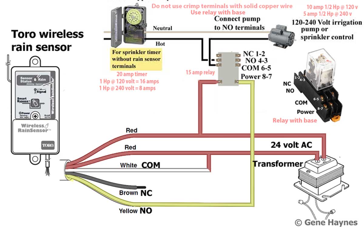
Intermatic Sprinkler Timer Wiring Diagram

Omron Mk2p S Wiring Diagram Sample

Staircase Timer Wiring Diagram - Using On Delay Timer And ...
0 Response to "37 timer relay wiring diagram"
Post a Comment