36 consider the circuit depicted in the diagram
Find step-by-step Physics solutions and your answer to the following textbook question: In an RC series circuit, emf ξ = 12.0 V, resistance R = 1.40 MΩ, and capacitance C = 1.80 μF. (a) Calculate the time constant. (b) Find the maximum charge that will appear on the capacitor during charging. (c) How long does it take for the charge to build up to 16.0 μC?. Consider the harmonically driven series LCR circuit shown. V max = 100 V I max =2 mA V Cmax =113 V The current leads generator voltage by 45o L and R are unknown. What is X L, the reactance of the inductor, at this frequency? Electricity & Magnetism Lecture 20, Slide 25
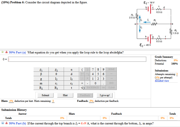
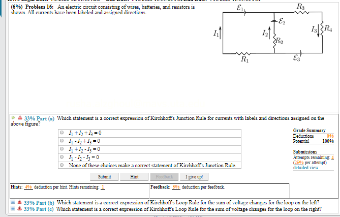
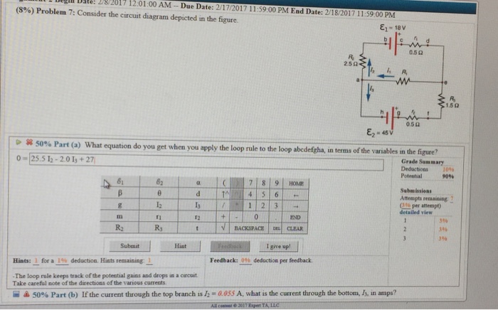
Problem Details. Consider the circuit diagram depicted in the figure. Part (a) What equation do you get when you apply the loop rule to the loop abcdefgha? Part (b) If the current through the top branch is I2 = 0.49 A, what is the current through the bottom I3, in amps? Learn this topic by watching Kirchhoff's Loop Rule Concept Videos.

Consider the circuit depicted in the diagram
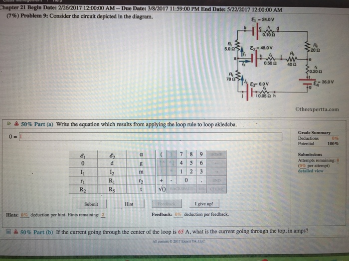
The open-circuit voltage / short-circuit current approach can be used to calculate the Thevenin equivalent for a known circuit. Consider the circuit from slide 4: + - V S R 1 R 2 I S 9V 6 mA 1.5 k! 3 k! Open-circuit voltage - Use whatever method you prefer. We'll use node voltage in this case. + - V S R 1 R 2 I S v a + - v oc YRF= YD ... Draw the circuit diagram and assign labels and symbols to all known and unknown quantities. Assign directions to the currents. The direction is arbitrary, but you must adhere to the assigned directions when applying Kirchhoff's rules Apply the junction rule to any junction in the circuit that provides new relationships among Physics. Physics questions and answers. Consider the circuit depicted in the diagram. (a) Write the equation which results from applying the loop rule to loop akledcba. (b) If the current going through the center of the loop is 65 A, what is the current going through the top, in amps? Question: Consider the circuit depicted in the diagram. (a ...
Consider the circuit depicted in the diagram. The electric potential difference of various spots in the circuit may be depicted by using a diagram known as electric potential diagram which is demonstrated underneath. In this illustration, the electric potential at A is = 9V because it's the bigger potential point. The electrical potential at H is = 0V because it is at negative point. What equation : 646641. Consider the circuit diagram depicted in the figure. What equation do you get when you apply the loop rule to the loop abcdefgha, in terms of the variables in the figure? 0 = If the current through the top branch is I_2 = 0.69 A, what is the current through the bottom, I_3, in amps? For a second example consider an electric RLC circuit with i(t) the input current of a current source, and v(t) the output voltage across a load resistance R. (Fig. 19.1.3) Using Kirchhoff's laws one may derive: which describes the dependence of the output voltage v(t) to the input current i(t). Given i(t) for t ≥0, the ini- Part (i) [3 marks] Consider the circuit depicted in Figure 4. The current source i s is a constant current supply, which is kept in place for a very long time until the switch is opened at time t = 0. Show that the initial capacitor voltage is given by v C(0
P 5.2-2 Consider the circuit of Figure P 5.2-2. Find i a by simplifying the circuit (using source transformations) to a single-loop circuit so that you need to write only one KVL equation to find i a. Figure P 5.2-2 . Solution: Finally, apply KVL: 16 10 3 4 0 2.19 A aa 3 a Consider the circuit diagram depicted in the fgure. It is known that two battery internal resistors r1and r2 are both 0.2Ω· = 12V and & = 24V. R2 16Ω 2. and Rs 262, but Ri is unknown. Caution: Current directions. Kirchhoff's Current Law (KCL) puts constraints on the currents in a circuit. Before we can state it we need a definition: Definition: A node is a place on the circuit where two or more circuit elements join. Kirchhoff's Current Law states the following. The algebraic sum of all currents at any node in a circuit is equal to zero. Question 1. (a) Consider the waveform below that has a period of T of 0.04 seconds. What is the rms voltage of this waveform? V(t) 15 V 0.01 s 0.02 s T ...1 answer · 0 votes: Thorder to find the Thevenin equivalent impedance we have to Short Circuit all independent sources A (3-34). lon F ZAB - ZTH ZTH= 51 + [03-14). || ...
The result for v3 becomes clear if we consider the part of the circuit enclosed by the ellipse on Figure 5(a) Given the voltages at these nodes, we can then use Ohm's law to calculate the currents. s 1 1eff v i= R+R (4.19) b 2 2 v i= R (4.20) and b 3 34 v i= R+R (4.21) 6.071, Spring 2006. Consider the circuit diagram depicted in the figure. Consider the circuit diagram depicted in the figure. What equation do you get when you apply the loop rule to the loop abcdefgha? If the current through the top branch is I_2 = 0.49 A. what is the current through the bottom, I_3, in amps? Consider the Circuit Diagram thee Ic Rc Slkr the given Data VBC = 400V VBC =0.4V where VB= Vec » VB VC=0-40 Vec-Ve=04 - from the arout Ic = vecave from ...1 answer · 2 votes: The maximum supply voltage is 0.707 V Consider the Circuit Diagram thee Ic Rc Slkr the given Data VBC = 400V VBC =0.4V where VB= Vec » VB VC=0-40 Vec-Ve=04 ... 1. Obtain the specification of the desired circuit. 2. Derive a state diagram. 3. Derive the corresponding state table. 4. Reduce the number of states if possible. 5. Decide on the number of state variables. 6. Choose the type of flip-flops to be used. 7. Derive the logic expressions needed to implement the circuit.
31 Consider The Circuit Diagram Depicted In The Figure ...
Consider the two conditioning circuits depicted in Fig. 1 and Fig. 2. The voltage source elements E 1 and E 2 model external voltage sources, eventually ...
Solved: Consider The Circuit Diagram Depicted In The Figur ...
PHY2049: Chapter 27 33 Circuit Problem (1) ÎThe light bulbs in the circuit are identical.What happens when the switch is closed? a) both bulbs go out b) the intensity of both bulbs increases c) the intensity of both bulbs decreases d) nothing changes Before switch closed: V a = 12V because of battery. V b =12 because equal resistance divides 24V in half.

GT500
This is shown in Diagram B. Now that all resistors are in series, the formula for the total resistance of series resistors can be used to determine the total resistance of this circuit: The formula for series resistance is Rtot = R1 + R2 + R3 + ... So in Diagram B, the total resistance of the circuit is 10 Ω.
Elementary circuits : Worksheet
An electric potential diagram is a conceptual tool for representing the electric potential difference between several points on an electric circuit. Consider the circuit diagram below and its corresponding electric potential diagram. The circuit shown in the diagram above is powered by a 12-volt energy source.
(6%) Problem 17: Consider the circuit diagram | Chegg.com
From equation (4.46) and (4.47), it is evident that current lags behind the applied voltage by π/2 in an inductive circuit. This fact is depicted in the phasor diagram. In the wave diagram also, it is seen that current lags the voltage by 90º (Figure 4.48). Inductive reactance XL The peak value of current Im is given by Im = Vm / ωL .

Circuit diagram of the home-made overdrive effect pedal ...
Answer to: Consider the circuit diagram depicted in the figure. a. What equation do you get when you apply the loop rule to the abcdefgha, in terms...
Consider The Circuit Diagram Depicted In The Figure ...
I 3 = _____ Problem 3: Consider the circuit depicted in the diagram. 4/6/2018 The Expert TA | Human-like Grading, Automated! 2/2 Part (a) Write the equation which results from applying the loop rule to loop akledcba.

Consider The Circuit Diagram Depicted In The Figure - Free ...
Solution for Consider the circuit depicted in figure. If Vs(t) =-8+2u(t).determine: Vc(0+), iL(0+), Vc(t=150ms)
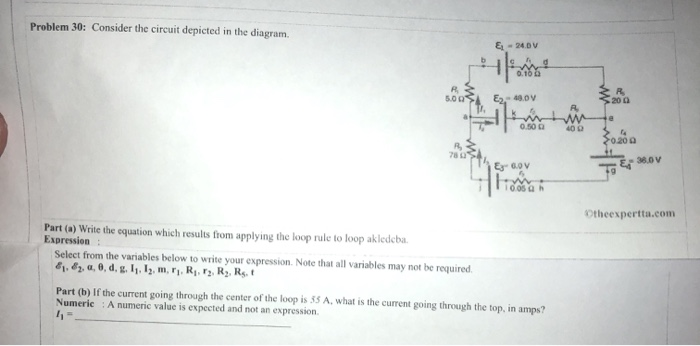
Solved: Problem 30: Consider The Circuit Depicted In The D ...
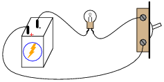
Electric circuits can be described in a variety of ways. An electric circuit is commonly described with mere words like A light bulb is connected to a D-cell . Another means of describing a circuit is to simply draw it. A final means of describing an electric circuit is by use of conventional circuit symbols to provide a schematic diagram of the circuit and its components.

Two-stage comparator circuit. | Download Scientific Diagram
Transcribed image text: (10%) Problem 5: Consider the circuit diagram depicted in the figure 0.5 Ω R2 2.5 Ω /2 R 1.5Ω 0.5 Ω 50% Part (a) what equation do you get when you apply the loop rule to the loop abcdergha, in terms of the variables in the figure? Grade= 100% Correct Answer Student Final Submission Feedback Correct! 012 R2+ 112 T3 R3 +32-62 0- 1-(Ti +R2) I2+(R3r2)13 2 Grade Summary ...

Couple at Werribee Gorge Circuit Track
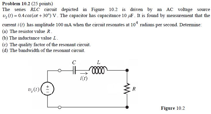
Before examining the driven RLC circuit, let's first consider the simple cases where only one circuit element (a resistor, an inductor or a capacitor) is connected to a sinusoidal voltage source. 12.2.1 Purely Resistive load Consider a purely resistive circuit with a resistor connected to an AC generator, as shown in Figure 12.2.1.

Consider The Circuit Diagram Depicted In The Figure - Free ...
Consider the circuit below. Since the 4-ohm resistor is in parallel with the capacitor, i(0+) = v C(0+)/4 = 0/4 = 0 A Also, since the 6-ohm resistor is in series with the inductor, v(0+) = 6i L(0+) = 0V. (b) di(0+)/dt = d(v R(0+)/R)/dt = (1/R)dv R(0+)/dt = (1/R)dv C(0+)/dt = (1/4)4/0.25 A/s = 4 A/s v = 6i L or ...

31 Consider The Circuit Diagram Depicted In The Figure ...
In the following circuit, consider the loop abc. The direction of the current through each resistor is indicated by black arrows. "going with current is drop, against current is gain" "The voltage gains when the current is flowing with the voltage" "drops 2 times at the split then gains when merging"

Podium of the 24 hour of Mans.
(14%) Problem 6: Consider the circuit depicted in the diagram. ... Hints remaining: Heedhack: U% deduction per feedhack 50 % Part (b) If the current going through ...4 answers · Top answer: the loop equation for this circuit is here we have the lubrication. Was it first revealed ...

Consider The Circuit Diagram Depicted In The Figure ...
Question Consider the circuit diagram consisting of capacitors and a battery pictured on the board. Find the equivalent capacitance, the charge on each capacitor and the... Question Consider the circuit diagram depicted in the figure. What equation do you get when you apply the loop rule to the loop abcdefgha, in terms...
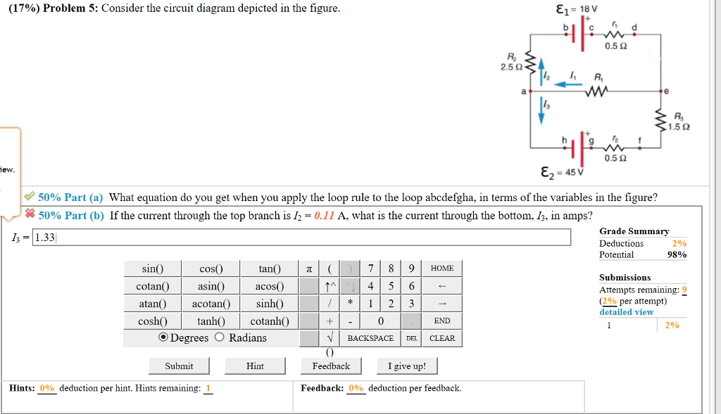
Solved: (17%) Problem 5: Consider The Circuit Diagram Depi ...
Now consider a diagram describing a parallel AC circuit containing a resistor, a capacitor, and an inductor. This time, the voltage across each of these elements of the circuit is the same; on the diagram, it is represented by the vector labeled .

Consider The Circuit Diagram Depicted In The Figure ...
[Q3] Consider the following state diagram for a synchronous circuit with one input X and one output Z. Analyze this state diagram and draw its circuit implementation using JK flip -flop (state Q0) and T flip -flop (state Q1) and MUX -4x1 for Z.

31 Consider The Circuit Diagram Depicted In The Figure ...
Physics. Physics questions and answers. Consider the circuit depicted in the diagram. (a) Write the equation which results from applying the loop rule to loop akledcba. (b) If the current going through the center of the loop is 65 A, what is the current going through the top, in amps? Question: Consider the circuit depicted in the diagram. (a ...
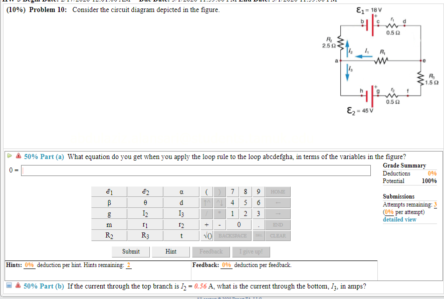
Solved: (10%) Problem 10: Consider The Circuit Diagram Dep ...
Draw the circuit diagram and assign labels and symbols to all known and unknown quantities. Assign directions to the currents. The direction is arbitrary, but you must adhere to the assigned directions when applying Kirchhoff's rules Apply the junction rule to any junction in the circuit that provides new relationships among

Consider The Circuit Diagram Depicted In The Figure ...
The open-circuit voltage / short-circuit current approach can be used to calculate the Thevenin equivalent for a known circuit. Consider the circuit from slide 4: + - V S R 1 R 2 I S 9V 6 mA 1.5 k! 3 k! Open-circuit voltage - Use whatever method you prefer. We'll use node voltage in this case. + - V S R 1 R 2 I S v a + - v oc YRF= YD ...
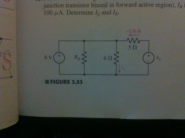
Solved: In The Circuit Depicted In Fig. 3.53 The Current I ...
Consider The Circuit Diagram Depicted In The Figure - Free ...

7 Consider The Circuit Diagram Depicted In The Figure ...

WD-40 Rider no. 31 on a bend at Silverstone

Consider The Circuit Diagram In The Figure - Free Wiring ...
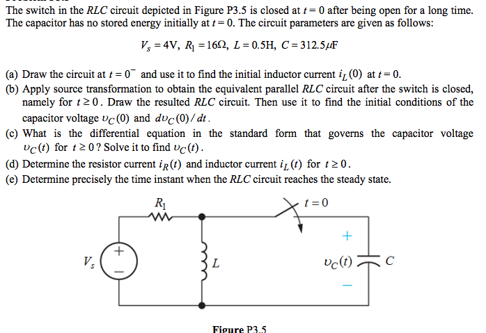
Solved: The Switch In The RLC Circuit Depicted In Figure P ...
Solved: Consider The Circuit Depicted In The Diagram. Writ ...

Schematic circuit diagram of the experimental setup. The ...
Solved: Consider The Circuit Diagram Depicted In The Figur ...
Consider The Circuit In The Diagram - Derslatnaback

Consider The Circuit Diagram Depicted In The Figure ...
Consider The Circuit Diagram Depicted In The Figure - Free ...
Solved: Consider The Circuit Depicted In The Diagram. (a ...

AC circuit containing only an inductor - Phasor diagram ...

Consider The Circuit Diagram Depicted In The Figure ...
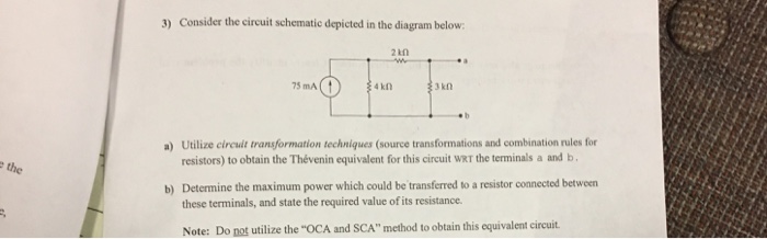
Solved: Consider The Circuit Schematic Depicted In The Dia ...
0 Response to "36 consider the circuit depicted in the diagram"
Post a Comment