39 draw a circuit diagram for the circuit of (figure 1)
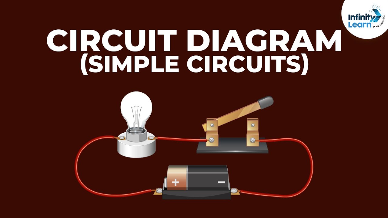
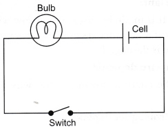
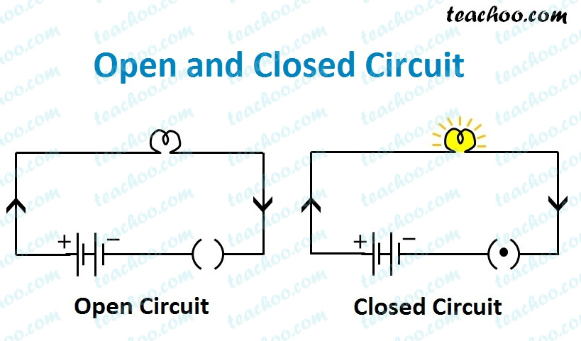
Book a free class now. Solution: In the given circuit, one end of the bulb is connected with one end of the cell while their other terminals are connected to a safety pin. However, the safety pin is not connected with one of the drawing pins. Thus, the circuit is not complete. Hence, the safety pin represents a switch in the 'OFF' position. Components of Circuit Diagram. In this section, let us learn about some important circuit diagram symbols. An electric cell: It provides the source of current. In its symbol, the larger terminal is positive, whereas the smaller one is the negative terminal. A battery: It is a combination of cells and its utility is the same as the cell.
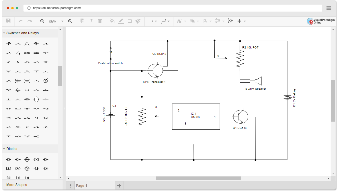
Circuit Diagram is a free application for making electronic circuit diagrams and exporting them as images. Design circuits online in your browser or using the desktop application.
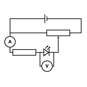
Draw a circuit diagram for the circuit of (figure 1)
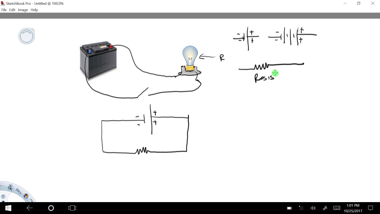
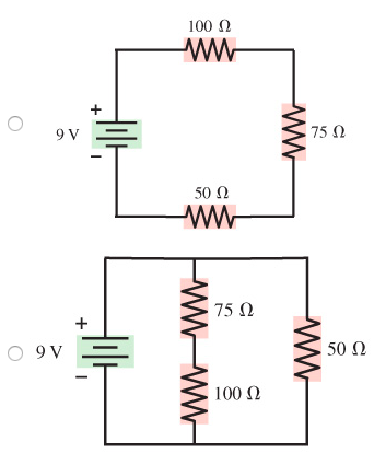
information (such as its ratings), and how each component is wired into the circuit. Block diagrams are the simplest type of drawing. As the name implies, block diagrams represent any part, component, or system as a simple geometric shape, with each block capable of representing a single component (such as a relay) or an entire system. The According to the circuit board to draw the circuit schematic is also a method and skill, the key is to be familiar with the common circuit of various components, so drawing is easier. 1. Method of drawing a triode amplifier circuit. 1) The first step is to draw the three-level tube circuit graphic symbol first. Hi. It is clear from the given figure that the two resistance is off 50 own and 100 home, uh, in Siris. Then this city's combination is in parallel with 75 homes and the battery off nine volt. So the city is in the city's is in parallel with these two. So the circuit diagram can be drawn. Like these are the two resistors, or 50 home and 100 homes which are in Siris.
Draw a circuit diagram for the circuit of (figure 1). Draw a circuit diagram for the circuit of FIGURE EX28.1. View Answer. (a) Draw a circuit diagram for an LFSR with n = 6 that generates a maximum-length sequence. (b) Add logic so that 000000 is included in the sequence. (c) Determine the 10 elements of the sequence starting in... View Answer. The construction of Circuit diagrams 6.0 Tutor Marked Assignment 1) In the figure below, change each AND gate to an OR gate, and change the OR gate to an AND gate. Then write the expression for output x. 2) Draw a logic circuit for the function F = (A + B)(B + C)(A + C), using NAND gates only. 3) Draw the circuit diagram for the expression x ... Micah Watson 4/26/2020 Principles to Physics II HW 08 CH 28 Fundamentals of Circuits from page 790 [2] Draw a circuit diagram for the circuit of FIGURE EX28.2. FIGURE EX28.2 [3] In FIGURE EX 28.3, what is the magnitude of the current in the wire to the Another means of describing a circuit is to simply draw it. ... On many occasions in Lessons 1 through 3, words have been used to describe simple circuits.
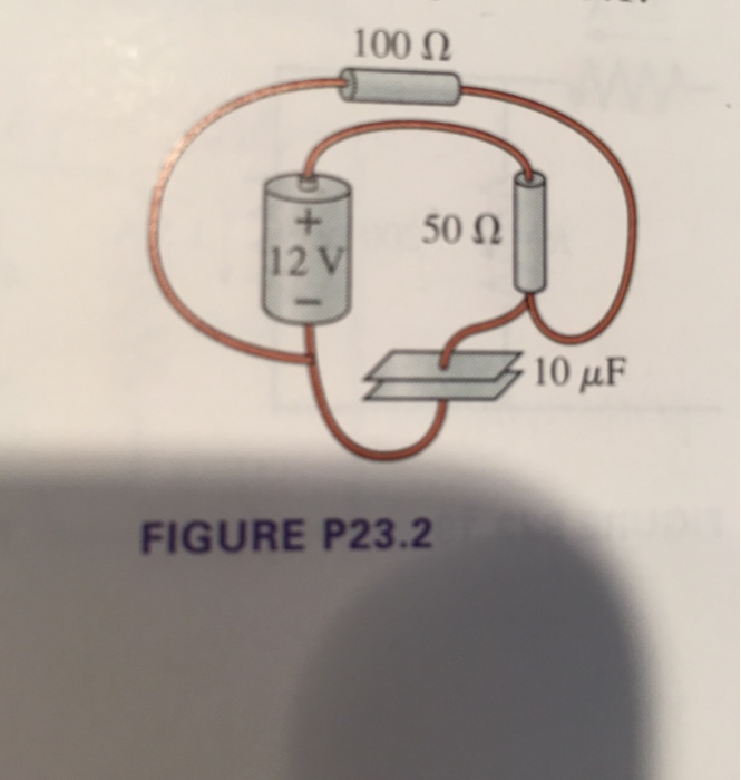
A circuit drawing allows you to visualize how components of a circuit are laid out. Lines connect fuses, switches, capacitors, inductors, and more. SmartDraw comes with thousands of detailed electrical symbols you can drag and drop to your drawings and schematics. SmartDraw also comes with a number of built-in circuit and wiring diagram ... Figure 1 of 1A circuit is shown in the figure. A 12-volt battery is connected by wires to two resistors and a capacitor. The positive terminal of the battery is ... So the circuit diagram can be drawn. Like these are the two resistors, or 50 home and 100 homes which are in Siris. Then there is a battery. Transcribed image text: Draw a circuit diagram for the circuit of (Figure 1). Choose the correct diagram. 10μF 12 V 50 Ω 100 50 0 10μF 12 V 100 ww 50 12 V Figure 1 of 1 100 Ω 10μF 100 100 + 50 12 V 12 V 50 10 μF 10μF WW wwW + +
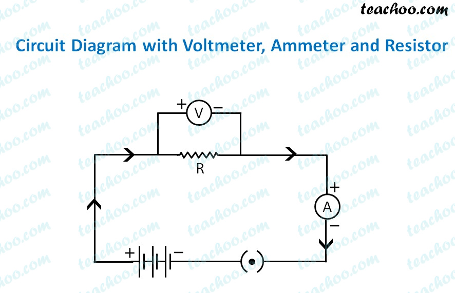
1-408-294-8324 thetech.org This activity is meant to extend your students' knowledge of the topics covered in our Simplicity of Electricity lab. In this activity, students will learn how to draw circuit diagrams and figure out if their circuit diagram will produce a working circuit. Grade Levels: 4-8 Estimated Time: 45 minutes Student ... Draw a circuit diagram to verify ohms law. Ohm's law states that the voltage across a conductor is directly proportional to the current flowing through it, provided all physical conditions and temperature remain constant. Draw a circuit diagram from a simple expression. Think about how you would draw a logic gate diagram for the Boolean expression: Q, equals, A, and, B, or, C, Q = A ∧ B ∨ C. You might draw the diagram in one of the two following ways: Figure 1: Option A. Figure 2: Option B. The correct diagram is option A. To draw a circuit diagram from a complex circuit follow the steps as: 1.Start with a collection of electrical symbols appropriate for diagram. 2.Draw circuits represented by lines from the complex given circuit. 3.Drag and drop symbols to the circuits as per the components given in the circuit and connect them appropriately.
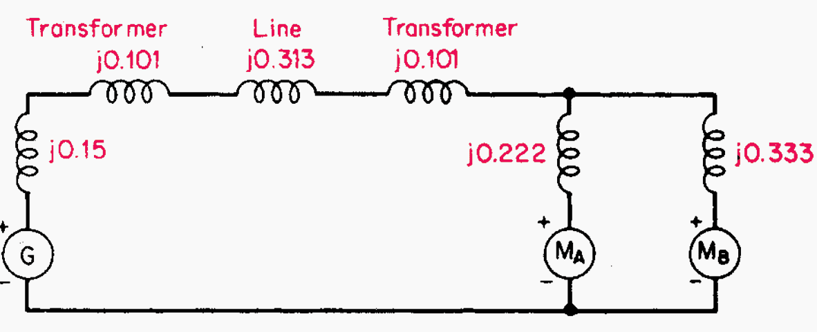
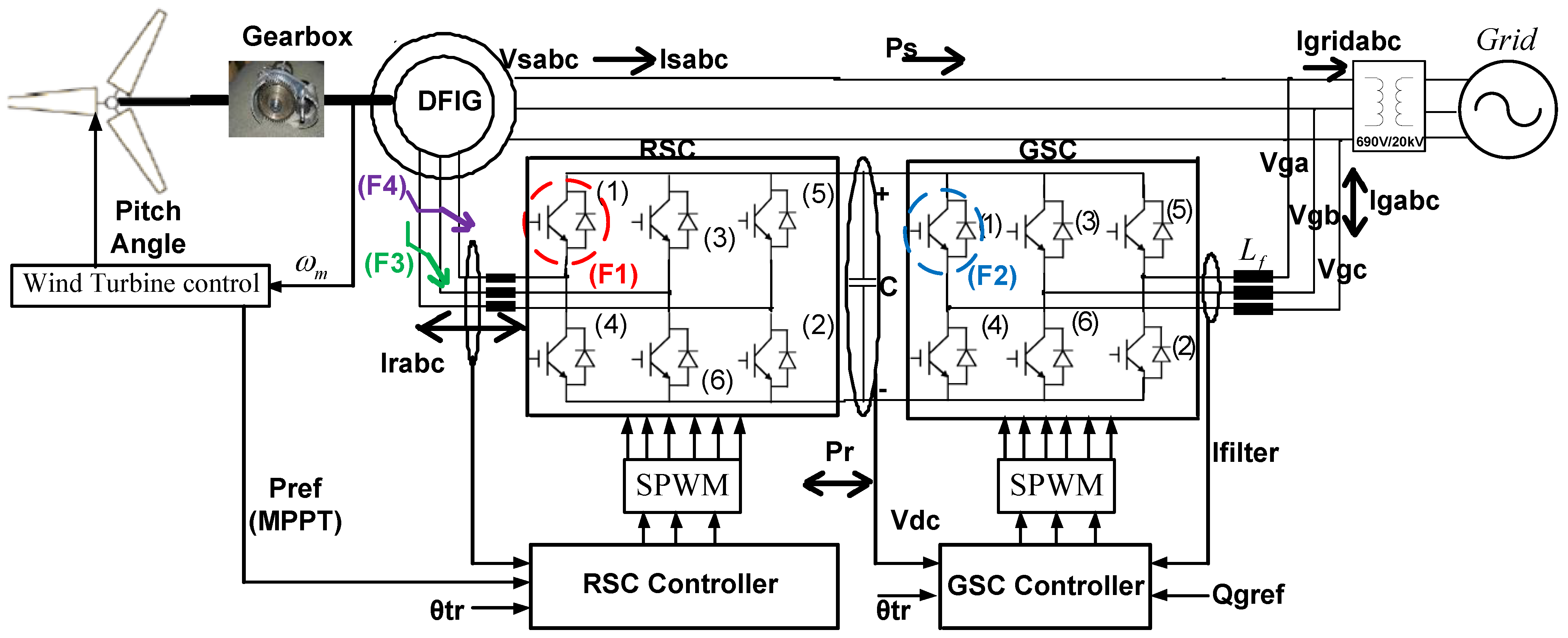
To simplify matters, only one of the three phases is represented. The parameters shown in the figure are typical of a 735-kV power system. Circuit to Be ...

System Dynamics (3rd Edition) Edit edition Solutions for Chapter 6 Problem 27P: Draw a block diagram of the circuit shown in Figure P6.15. The inputs are v1 and v2. The output is i2.Figure P6.15 …

We've seen the Symbols of the Most Common Electrical Components that are used to represent them. In this video, we will look at how to draw Circuit Diagrams ...
1 of 1A circuit is shown in the figure. A 12-volt battery is connected by wires to two resistors and a capacitor. The positive terminal of the battery is ...

Problem: Draw the circuit diagram for the circuit of (Figure 1).Choose the correct options. FREE Expert Solution. From the positive terminal, we meet the 50Ω ...
Draw a circuit diagram for the circuit of (Figure 1).

Question: Lamun Problem 23.3 Draw a circuit diagram for the circuit of (Figure 1). Part A Choose the correct diagram. 502 2012 300 o 6V Figure 50F 1 of 1 WWW 400 800 40 Ω 20 40 50 F 80 30 80 Ω 6 V 502 50F 5002 30 6V sono ROL Problem 23.3 Draw a circuit diagram for the circuit of (Figure 1). 500 200 802 tms www 2002 30 6V 50F Figure < 1 of 1 ...

Circuit diagram. The working of a buck regulator is explained using the circuit diagram as shown in Figure 1. The regulation is normally achieved by PWM (Pulse Width Modulation) at a fixed frequency and using the switch ${S_1}$ shown in the circuit diagram can be a conventional thyristor i.e., SCR, a GTO thyristor, a power transistor, or a MOSFET.

The circuit diagram to represent the circuit shown in figure can be drawn as mentioned above in the fig. Answer verified by Toppr. 174 Views.

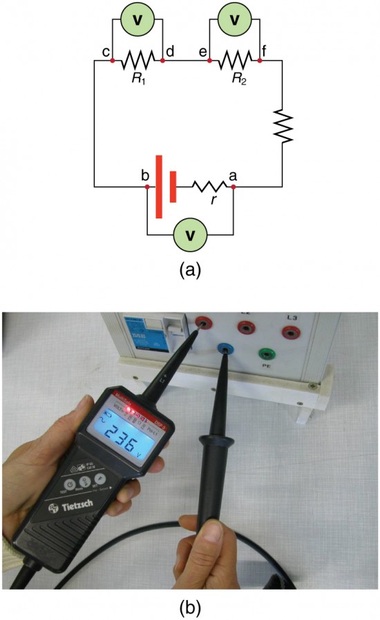
Figure 2—Circuit drawing Line diagram: a one-line diagram or single-line diagram is a simplified notation for representing an electrical system. The one-line diagram is similar to a block diagram except that electrical elements such as switches, circuit breakers, transformers, and capacitors are shown by
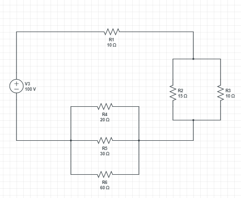
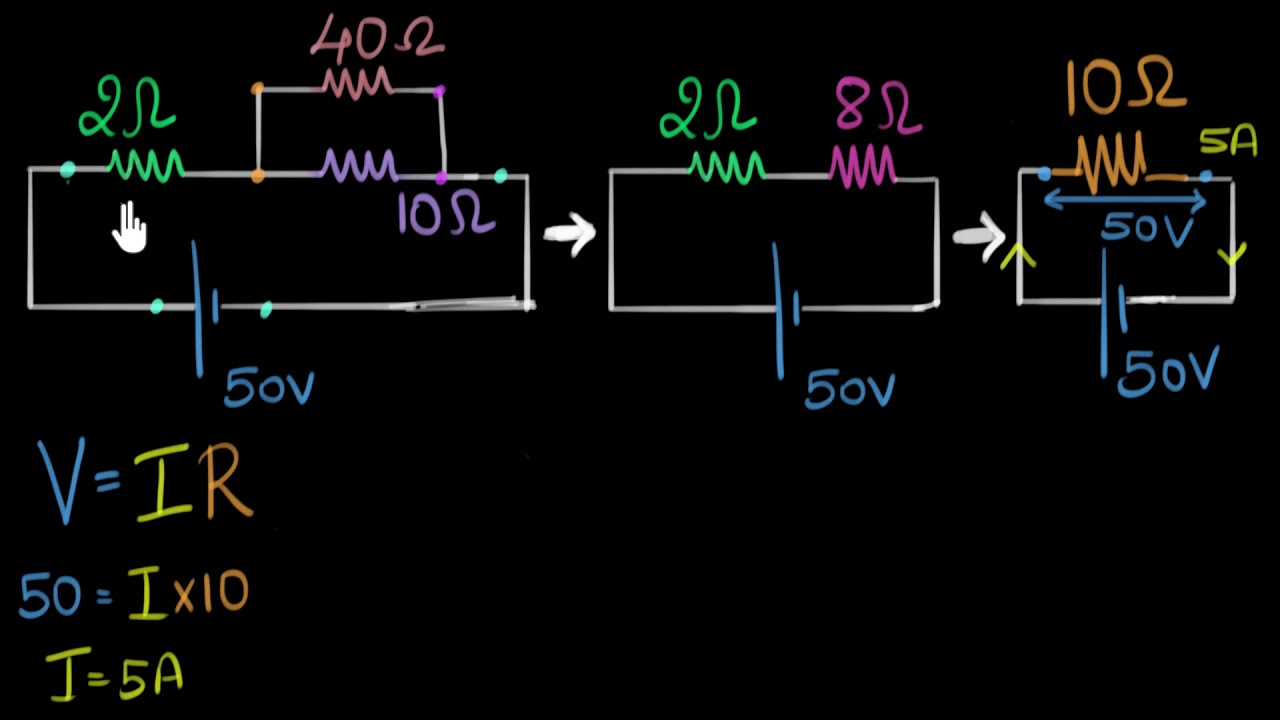
Find R 45 and R 67 ¶. To simplify the circuit diagram, we'll combine the resistors in series. For resistors in a simple series circuit: R t = R 1 + R 2 + R 3... + R n. Since resistors R 4 and R 5 are in simple series: R 45 = R 4 + R 5. Since resistors R 6 and R 7 are in simple series: R 67 = R 6 + R 7. We can easily calculate this with Python.

Figure shows the circuit diagram of a square-law modulator. The signal applied to the non linear devices is relatively weak, such that it can be represented by a square law: v2 (t) = a1v1 (t) + a2v21 (t), where a1 and a2 are constant, and v1 (t) is the input voltage and v2 (t) is the output voltage.
In series means the cells are connected end-to-end, and the current flows through each cell in turn. 1. Draw a circuit diagram of the circuit in Figure 3 in ...

View the circuit as a schematic diagram, or switch to a lifelike view. Transcribed image text: Draw a circuit diagram for the circuit of (Figure 1). Choose the correct diagram. 10μF 12 V 50 Ω 100 50 0 10μF 12 V 100 ww 50 12 V Figure 1 of 1 100 Ω 10μF 100 100 + 50 12 V 12 V 50 10 μF 10μF WW wwW + +
Explanation. Step 1. 1 of 2. The circuit diagram of the basic inverting amplifier configuration is shown in figure below. Expression for the closed-loop voltage gain. A v A_v A v . if the circuit is: A v = v o v i n A_v=\frac {v_o} {v_ {in}} A v = v in v o . Input voltage.
3.1 Consider the circuit shown in Figure P3.1. (a) Show the truth table for the logic function f. (b) If each gate in the circuit is implemented as a CMOS gate, how many transistors are ... This mathematical expression is similar to that obtained in Problem 3.1. Therefore these two circuit diagrams are functionally equivalent.
Experts are tested by Chegg as specialists in their subject area. We review their content and use your feedback to keep the quality high. Transcribed image text: Draw a circuit diagram for the circuit of (Figure 1).

Slide Topic: Sample Circuit Diagrams From Both The No Labels N Conditions Only Download Scientific Diagram Draw A Circuit Diagram For The Circuit Of Figure 1: Presentation Time: 24+ minutes: File Format: PPTX: File size: 1.5mb: Number of Pages: 55+ slides: Publication Date: December 2017
Solved: Draw A Circuit Diagram For The Circuit Of (Figure ... | Chegg.com. science. physics. physics questions and answers. Draw A Circuit Diagram For The Circuit Of (Figure 1) . Choose The Correct Diagram: Question: Draw A Circuit Diagram For The Circuit Of (Figure 1) . Choose The Correct Diagram:
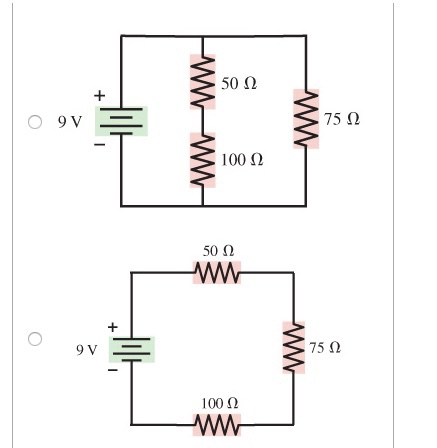
Hi. It is clear from the given figure that the two resistance is off 50 own and 100 home, uh, in Siris. Then this city's combination is in parallel with 75 homes and the battery off nine volt. So the city is in the city's is in parallel with these two. So the circuit diagram can be drawn. Like these are the two resistors, or 50 home and 100 homes which are in Siris.

According to the circuit board to draw the circuit schematic is also a method and skill, the key is to be familiar with the common circuit of various components, so drawing is easier. 1. Method of drawing a triode amplifier circuit. 1) The first step is to draw the three-level tube circuit graphic symbol first.

information (such as its ratings), and how each component is wired into the circuit. Block diagrams are the simplest type of drawing. As the name implies, block diagrams represent any part, component, or system as a simple geometric shape, with each block capable of representing a single component (such as a relay) or an entire system. The


0 Response to "39 draw a circuit diagram for the circuit of (figure 1)"
Post a Comment