41 spectrum analyzer block diagram
spectrum analyzer will be examined. 7.1 Modulation With the proper equipment, radio signals can be transmitted and received over large distances. Information may therefore be exchanged over large distances by encoding information on radio ... A block diagram of the demodulation process is shown in Figure 5. cos ... The figure below shows the block diagram representation of a spectrum analyzer with digital display: As we can see the spectrum analyzer is composed of components like RF attenuator, mixer, IF filter, detector, sweep generator, local oscillator and display unit. So, let us now understand the operation performed by each block individually.
Block Diagram Description Spectrum analyzer users need to understand major analyzer functional blocks. While most of the choices described here are made automatically, manual selections are possible and can be helpful. The DC block prevents DC voltage from entering the instrument, and allows measuring lines with DC power.
Spectrum analyzer block diagram
Block diagram for spectrum analyzer. Source publication A Technique to Accurately Predict EMI Noise Spectrum in Wide Frequency Ranges Based on the Principles of Spectrum Analyzers Figure 2: A diagram of an RF attenuator, the first block of a spectrum analyzer. An RF attenuator, shown in Figure 2, ensures the signal enters the mixer at an optimum level. If a signal is too high in amplitude, it may overload the mixer, leading to distortion. This component protects the analyzer from damage. Spectrum Analyzer Block Diagram The crucial component used in the construction of the analyzer is a swept-tuned receiver. The device consists of a mixer, detector, RF type attenuator, local oscillator a LED display section.
Spectrum analyzer block diagram. Spectrum Analyzer with Block Diagram. A Spectrum Analyzer is a frequency selective voltage indicator. That is it indicates the magnitude of the input signal in the frequency domain. The voltage indicator incorporated in a spectrum analyzer is a Cathode Ray Tube. Therefore we can say that a spectrum analyzer is a special purpose cathode ray ... The spectrum analyzer, like an oscilloscope, is a basic tool used for observing signals. Where the oscilloscope provides a window into the time domain, the spectrum analyzer provides a window into the frequency domain, as depicted in Figure 1. Figure 2 depicts a simplified block diagram of a swept-tuned superheterodyne spectrum analyzer. The spectrum analyzer, like an oscilloscope, is a basic tool used for observing signals. Where the oscil-loscope provides a window into the time domain, the spectrum analyzer provides a window into the frequency domain, as depicted in Figure 1. Figure 2 depicts a simplified block diagram of a swept-tuned super-heterodyne spectrum analyzer. The FFT spectrum analyzer can be considered to comprise of a number of circuit different blocks: FFT Spectrum Analyser Block Diagram. Analogue front end attenuators / gain: The test instrument requires stages at the input of the FFT analyser to ensure that the signal is at the required level for the analogue to digital conversion. These stages ...
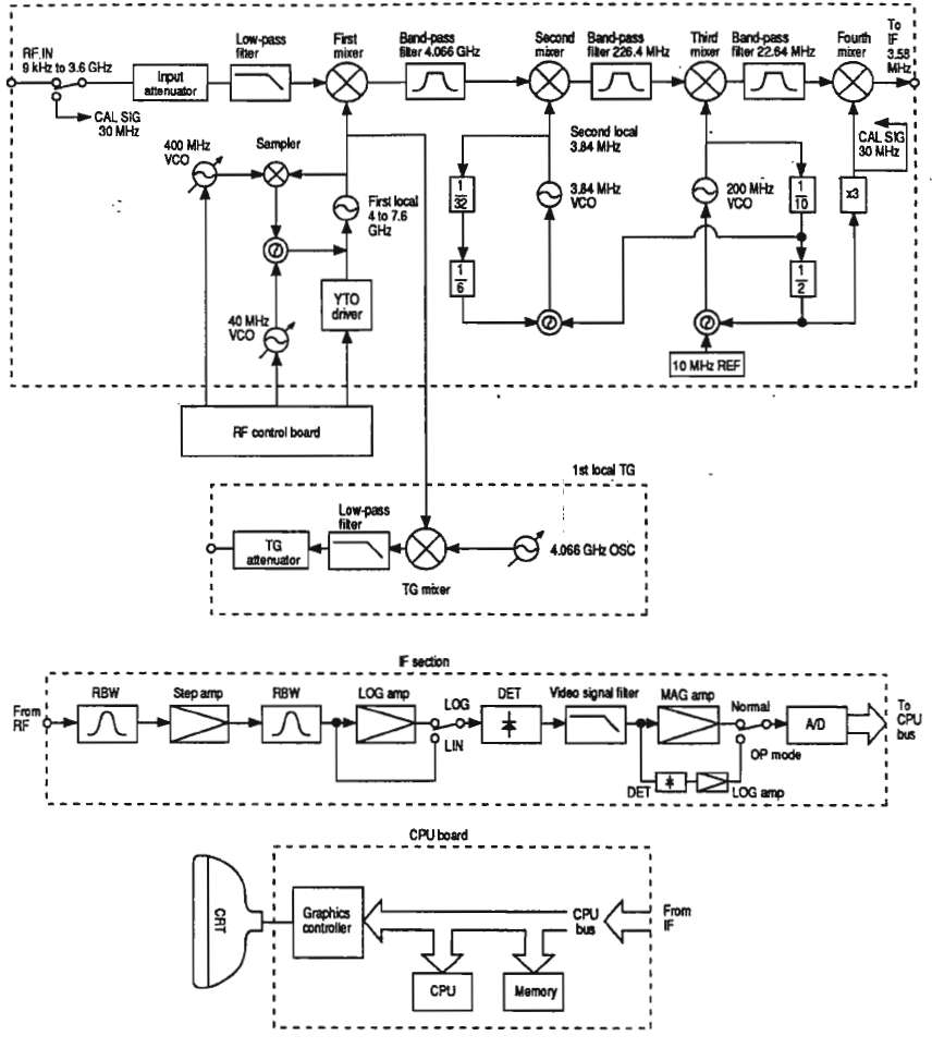
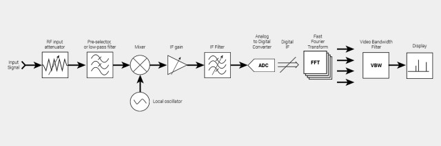
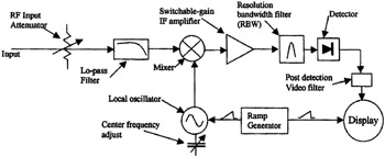
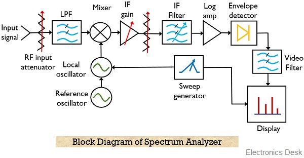
Block Diagram of a Mass Spectrometer Ion Source Mass Analyzer Detector "High" Vacuum Sample In Computer 400 600 800 1000 1200 1400 1600 1800m/z 0 20 40 60 80 100 Relative Abundance Mass Analyzer Activation or Reaction Tandem Mass Spectrometry or MS/MS Analyzer Block Diagram Block Diagram. The block diagram of the spectrum analyzer is shown above. It consists of an input attenuator, which attenuates the input radio frequency signal. The attenuated signal is fed to a low pass filter to eliminate the ripple content. The filtered signal is mixed with a voltage tuned oscillator, and fed to an ... a spectrum analyzer. 2.2 Spectrum Analyzer Block Diagram and Theory of Operation The main components of Spectrum Analyzer are an RF input attenuator, input am-plifier, mixer, IF amplifier, IF filter, envelope detector, video filter, CRT display, LO, ramp generator(see Fig - 2 ). Lets describe each component individually Spectrum Analyzer Block Diagram The crucial component used in the construction of the analyzer is a swept-tuned receiver. The device consists of a mixer, detector, RF type attenuator, local oscillator a LED display section. Spectrum Analyzer with Block Diagram. A Spectrum Analyzer is a frequency selective voltage indicator.
This video describes the architecture and functionality of the Spectrum Analyzer. Add a Spectrum Analyzer block to your block diagram.. If your model uses a variable-step solver, also add a Rate Transition block and connect it to the input of the Spectrum Analyzer, setting the Output port sample time to the sample time you wish the Spectrum Analyzer to use.. If your model uses a local solver, then it produces output physical signals with discrete sample times and you do not ... Figure 3: Simplified block diagram of an analog swept spectrum analyzer. Diagram applies in principle also for spectrum analyzers with narrow-band digital back ends, as e.g. the R&S FSP and R&S FSU. The block diagram in Figure 3 shows the key elements that contribute to inherent intermodulation on a spectrum analyzer. Spectrum analyzers usually display raw, unprocessed signal information such as voltage, power, period, waveshape, sidebands, and frequency. They can provide you with a clear and precise window into the frequency spectrum. Depending upon the application, a signal could have several different characteristics. For example, in communications, in
Block diagram for a digital cross-correlation spectrum analyzer. In our... | Download Scientific Diagram
Also, a spectrum analyzer uses complex circuitry compared with an Oscilloscope. As a result of this, the cost of a spectrum analyzer is usually quite high. Up. 3.Simplified Block Schematic of Heterodyne Receiver: The figure above shows a simplified block diagram of a super-heterodyne receiver.

Homebrew spectrum analyser
Figures 1-2 a, b, c. Simplified Block Diagram of Swept Spectrum Analyzer (a), Vector Signal Analyzer (b), and Real-Time Spectrum Analyzer (c). a) Swept Tuned Spectrum Analyzer (SA) b) Vector Signal Analyzer (VSA) c) Real-Time Spectrum Analyzer (RSA6100 Series + Option 110) Attenuator Attenuator Low-Pass Low-Pass RF Downconverter Real-Time Digital

Audio Spectrum Analyzer with the Linduino | Analog Devices
Superheterodyne or swept frequency spectrum analyzer block diagram . The frequency of the local oscillator governs the frequency of the signal that will pass through the intermediate frequency filter. This is swept in frequency (linearly increasing in frequency) so that it covers the required band. The sweep voltage used to control the ...

Audio Spectrum Analyzer
The spectrum analyzer, used for analyzing the signals are of RF range is called superheterodyne spectrum analyzer. Its block diagram is shown in below figure. The working of superheterodyne spectrum analyzer is mentioned below. The RF signal, which is to be analyzed is applied to input attenuator. If the signal amplitude is too large, then it ...
Real time spectrum analyzers vs. swept spectrum analyzers
A block diagram of an audio spectrum analyzer. SPECTRUM ANALYZERS •The real-time, or multichannel. analyzer is basically a set of stagger-tuned bandpass filters connected through an electronic scan switch to a CRT. The composite amplitude of the signal within each filters bandwidth is displayed as a ...

Block diagram of the CAROLS radiometer and (FFT) spectrum ...
MS2711 Spectrum Analyzer Block Diagram. 13. Press the RBW soft key and use the Up/down arrow key to select 10 kHz. Press ENTER to set the resolution band-width to 10 kHz. 14. Press the VBW soft key and use the Up/down arrow key to select 3 kHz. Press ENTER to set the video bandwidth to 3 kHz. 15.
SPECTRUM ANALYZER 9 kHz GHz - ppt download
In this video, i have explained Spectrum Analyzer block Diagram, Basics and Working with following outlines.1. Spectrum Analyzer basics2. Spectrum Analyzer B...

Rohde & Schwarz Spectrum Analyzer Fundamentals Primer - RF ...
Agilent Technologies 8 Hints For Spectrum Analysis. Mini Audio Analyzer Circuit Diagram And Instructions. Block Diagram For Spectrum Analyzer Scientific. Audio Spectrum Analyzer Easyeda. Spectrum Analyzers. An Inexpensive Spectrum Analyzer For The Radio. Spectrum Analyzer And Equalizer Designs. Audio Spectrum Analyzer Circuit 400led Electronics ...
spectrum Analyzer SPECTRUM ANALYZERS The problems associated with
Spectrum Analyzer Block Diagram 15. Major blocks in a spectrum analyzer are:- 1] RF input attenuator, 2] Mixer, 3] IF (Intermediate Frequency) gain, 4] IF filter, 5] Detector, 6] Video filter, 7] Local oscillator, 8] Sweep generator, and 9] CRT display. 16. IF Filter The IF filter is a bandpass filter which is used as the window for detecting ...
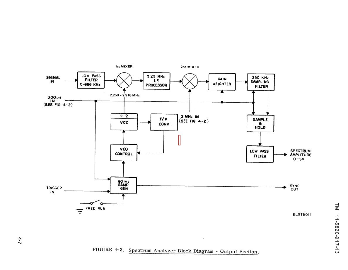
Figure 4-3. Spectrum Analyzer Block Diagram - Output Section
seems confusing now - as we discuss the block diagram, the concept will become clearer. We will first go into more detail as to how the swept spectrum analyzer works. Then we will compare that architecture to the architecture of a modern FFT analyzer.
Advantest R3131A Spectrum Analyzer 9KHz-3GHz - Page 1
This project is for making a 32-band audio (music) frequency spectrum analyzer / visualizer using Arduino. Expected audience of this project is any audio enthusiast, student or a beginner who has basic understanding of electronic components, Arduino and C programming. Components used in this project are low cost items and are easy to assemble.
Spectrum Analysis Back to Basics Agilent Technologies Back
Spectrum Analyzer Block Diagram The crucial component used in the construction of the analyzer is a swept-tuned receiver. The device consists of a mixer, detector, RF type attenuator, local oscillator a LED display section.

Signal Generators and Analyzers (part 4)
Figure 2: A diagram of an RF attenuator, the first block of a spectrum analyzer. An RF attenuator, shown in Figure 2, ensures the signal enters the mixer at an optimum level. If a signal is too high in amplitude, it may overload the mixer, leading to distortion. This component protects the analyzer from damage.

Constructing Scotty Sprowls' 1 GHz RF Spectrum Analyzer
Block diagram for spectrum analyzer. Source publication A Technique to Accurately Predict EMI Noise Spectrum in Wide Frequency Ranges Based on the Principles of Spectrum Analyzers
Simplified Spectrum Analyzer Block Diagram | Signal Hound

Simplified block schematic of a nonlinear vector network ...

Do I need a Spectrum Analyzer or an Oscilloscope?
New Arduino Project: Spectrum Analyzer?

Spectrum Analyzer with Block Diagram - Electronics and ...
Spectrum Analyzer : Working Principle, Classfication & Its Applications

EEC2: Block Diagram: Spectrum Analyzer - YouTube

FFT Spectrum Analyzer: Fast Fourier Transform ...

EA4EOZ, an amateur radio electronic enthusiast: Repairing ...
GBPPR 1 GHz RF Spectrum Analyzer

Spectrum Analyzer - Electronics Club Spectrum Analyzer

Spectrum analyzer on TV head

Teardown, Repair & Analysis of an Agilent E4443A 3Hz - 6 ...

Spectrum Analyzer Terminologies | Spectrum Analyzer Glossary
Block Diagram Of The Spectrum Analyzer Audio Spectrum Analyzer Block Diagram, Page, Label, Paper Transparent Png – Pngset.com
3.2: The Swept-Tuned Spectrum Analyzer | Engineering360

39 spectrum analyzer block diagram - Diagram Resource 2022

Review: Signal Hound BB60C real time 6 GHz spectrum ...

Spectrum Analyzer with Block Diagram ~ Electronics and ...

Block diagram of the correlation spectrum analyzer ...
What is Spectrum Analyzer? Block Diagram, Working and ...
File:Signal analyzer block diagram.png - Wikipedia

What Is Your Old Spectrum Analyzer Hidding From You?

Siglent SSA3021X Spectrum Analyser RF Block Diagram | Flickr
Optical Spectrum Analyzer function | OSA Application Note

1 GHz RF Spectrum Analyzer - Resource Detail - The DXZone.com

Rohde & Schwarz: Spectrum Analyzer Fundamentals - RF Cafe
0 Response to "41 spectrum analyzer block diagram"
Post a Comment