40 natural gas plant process flow diagram
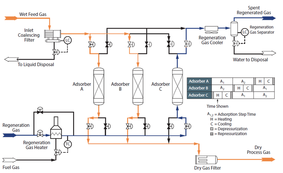
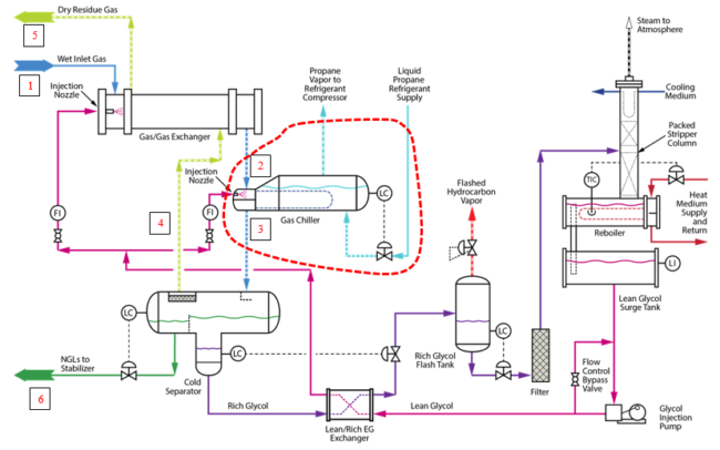
this video explain the flow sheet of the dehydration process diagram hope you enjoy it. this video explain the flow sheet of the dehydration process diagram hope you enjoy it. Bijan Elahi, in Safety Risk Management for Medical Devices, 2018. 12.7.1.3 Process Flow Diagram. Process Flow Diagrams (PFDs) are a graphical way of describing a process, its constituent tasks, and their sequence. A PFD helps with the brainstorming and communication of the process design. The PFMEA process needs a complete list of tasks that comprise the process under analysis.
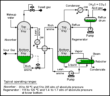
Figure 5.3-2. Flow diagram of the amine process for gas sweetening. 5.3.3 Emissions4-5 Emissions will result from gas sweetening plants only if the acid waste gas from the amine process is flared or incinerated. Most often, the acid waste gas is used as a feedstock in nearby sulfur recovery or sulfuric acid plants.

Natural gas plant process flow diagram
The reformed gas that has passed through a cooling process of the plant must now have its pressure boosted in order for the Methanol Synthesis reaction to occur. Compression is achieved in 3 stages, Low, Medium and High. All these compression stages are driven by one large and powerful gas fired Gas Turbine, that itself Natural Gas Feeds . Recycle Feeds . Oxidizer Feeds . Product Feeds . Fuel Burning Equipment . Thermal Oxidizer . Figure C -1: Ethane Cracker Process Flow Diagram . ... Polyethylene Plant A Process Flow Diagram Product Feeds Vent Streams Recycle Feeds Flare Feeds Fuel Burning Equipment PM Pollution Control Devices POLYMERIZATION PA-PE-202 ... ... natural gas purification system is mainly composed of the gas sweetening unit (GSU), dehydration unit (DU), sulfur recovery unit (SRU), tail ...
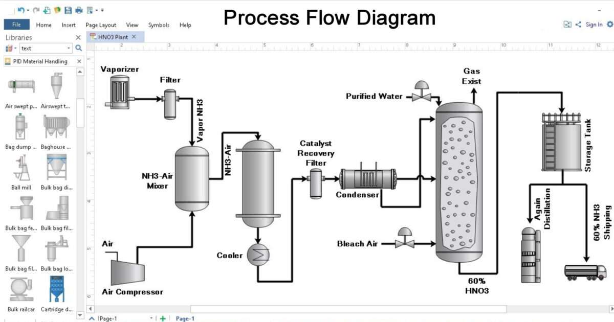
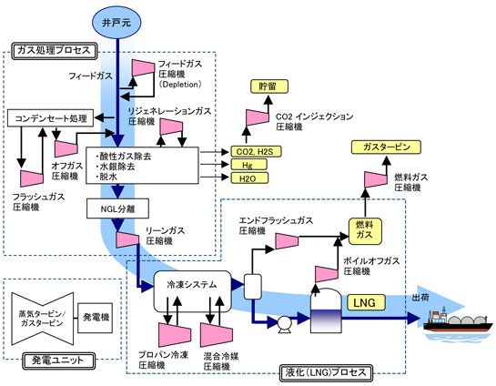
Natural gas plant process flow diagram. A process flow diagram for a plant based on two-step reforming is shown in Figure 1. By combining the two reforming technologies, it is possible to adjust the synthesis gas to obtain the hydrogen is obtained from either the catalytic steam reforming of natural gas (methane [CH4]) or naphtha, or the electrolysis of brine at chlorine plants. In the U. S., about 98 percent of synthetic ammonia is produced by catalytic steam reforming of natural gas. Figure 8.1-1 shows a general process flow diagram of a typical ammonia plant. Steam Methane Reforming & Water Gas Shift Steam Natural Gas Reforming Reactor High Temperature Shift Reactor Low Temperature Shift Reactor Hydrogen Purification Fuel Gas Flue Gas Hydrogen Methanation Reactor CO2 • Reforming. Endothermic catalytic reaction, typically 20‐30 atm & 800‐880°C (1470‐ 1615°F) outlet. CH 4 + H 2 O CO + 3 H •Introduction -Liquefied Natural Gas (LNG) •Block diagram of LNG plant ... LNG plant block diagram End flash HHC Extraction CH4/N2 Fuel gas Power and Heat. Gas conditioning (pre-treatment) ... Typical amine sour gas removal process Source : DOW chemicals P=65 bara T=45 oC 5.0 % CO2 MEG wash Amine wash P=2 bara T=44 oC
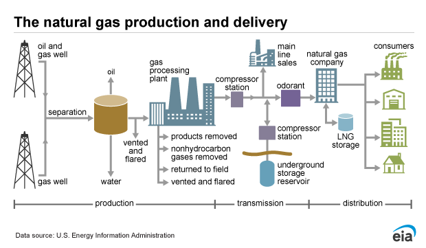
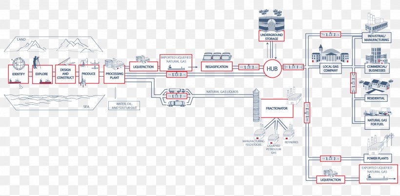
The general process flow for an amine sweetening plant is shown in figure XI-B.2. The feed gas (sour gas) containing H2S and/or CO2 always must enter the plant through an Inlet Separator (or feed gas knock-out drum) to remove free liquids and/or entrained solids. The process flow diagram example "Natural gas condensate - PFD" was drawn using the ConceptDraw PRO software extended with the Chemical and Process Engineering solution from the Chemical and Process Engineering area of ConceptDraw Solution Park. ... the help of Chemical Process Flow Diagram engineers can easily specify the general scheme of the ... Description of a natural-gas processing plant. There are a variety of ways in which to configure the various unit processes used in the treatment of raw natural gas. The block flow diagram below is a generalized, typical configuration for the processing of raw natural gas from non-associated gas wells. It shows how raw natural gas is processed ... A generalized natural gas flow diagram is shown in Figure 12.2 [7]. After initial scrubbing to remove particles, the first step in natural gas processing is the removal of condensate (oil) and water that is achieved by controlling the temperature and pressure of the inlet stream from the well, as shown in Figure 12.4.
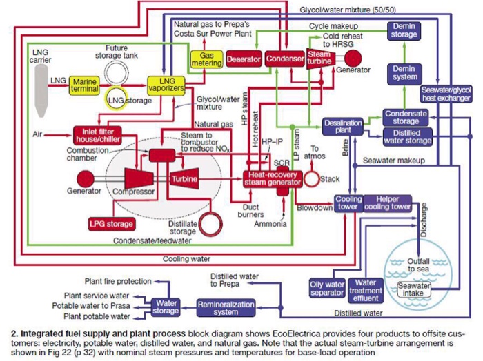
Natural gas power plants generate electricity by burning natural gas as their fuel.There are many types of natural gas power plants which all generate electricity, but serve different purposes. All natural gas plants use a gas turbine; natural gas is added, along with a stream of air, which combusts and expands through this turbine causing a generator to spin a magnet, making electricity. The plant is normally operated with a higher steam content than required to prevent elemental carbon from being deposited in the catalyst bed (Steam Reforming, 2014). The pressure swing adsorption will isolate the hydrogen desired from any residual gases that are later used as fuel. Figure 1 below shows the process flow diagram of the process. Historically, you can find references to natural gas dating back to 1,000 B.C.. With advances in technology . the U.S. currently has an estimated 100-year supply of shale gas. The process of liquefying natural gas is comparatively new and was only discovered in 1820. The first LNG plant was built in 1912 and LNG shipping began around 1959. In a CCGT plant the thermal efficiency is extended to approximately 50-60 per cent, by piping the exhaust gas from the gas turbine into a heat recovery steam generator. However the heat recovered in this process is sufficient to drive a steam turbine with an electrical output of approximately 50 per cent of the gas turbine generator.
In this Video we have covered the followingGas Processing Plant Process Flow DiagramGas Processing Plant Process EquipmentsGas Processing Plant Process Equip...

A Process Flow Diagram (PFD) is a diagram which shows the relationships between the main components in a system. Process Flow Diagrams are widely used by engineers in chemical and process engineering, they allows to indicate the general flow of plant process streams and equipment, helps to design the petroleum refineries, petrochemical and chemical plants, natural gas processing plants, and ...
a Fischer-Tropsch plant for converting Natural Gas to Liquid transportation Fuels." Argonne National Laboratory. •Korea study (2009) -Chul-Jin Lee, Youngsub Lim, Ho Soo Kim, and Chonghun Han. "Optimal Gas- ... Appendix A - Process flow diagram Biofuels and Emerging Technologies Team

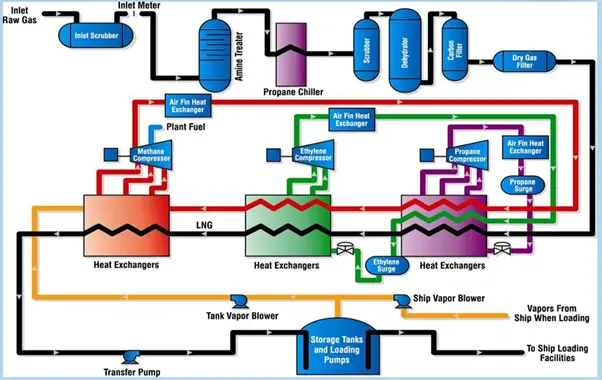
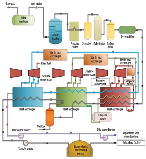
Natural Gas. CO. 2 /H. 2. S Removal. Dehydration. Heavy Component Removal. Natural Gas Liquefaction. Transportation. Flow Diagram for a Typical LNG Plant
Download scientific diagram | Process flow diagram of a typical H 2 plant from publication: Triple-Objective Optimization of an Industrial Hydrogen Plant | In this work the performance of an ...
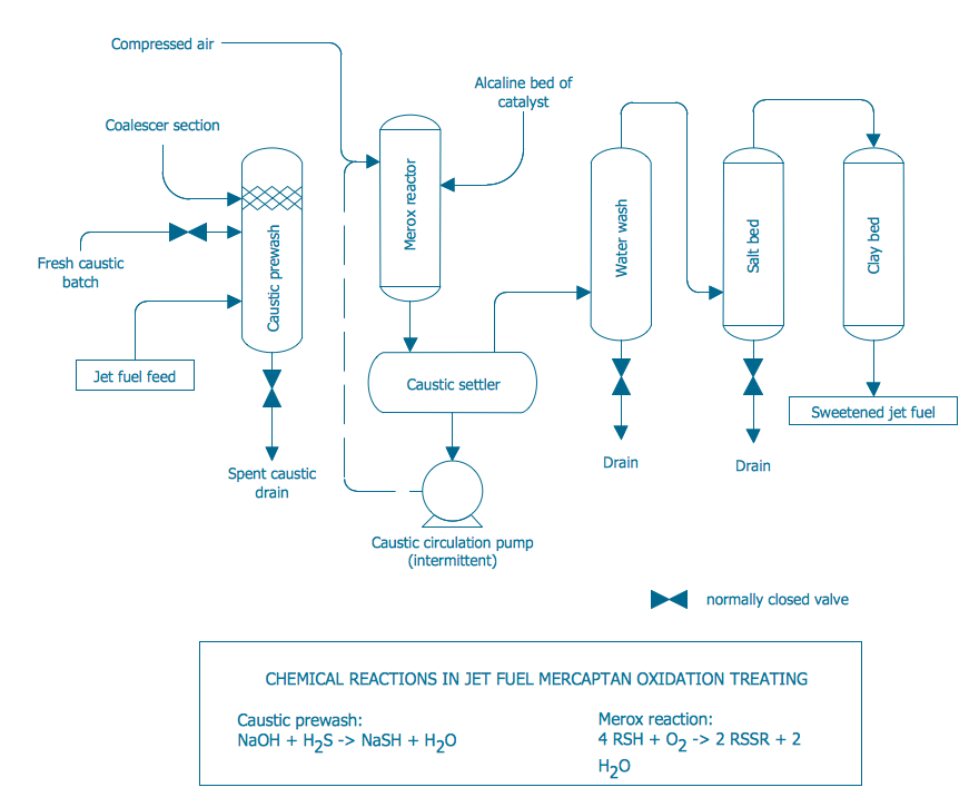
-jet-fuel-mercaptan-oxidation-treating---pfd.png--diagram-flowchart-example.png)
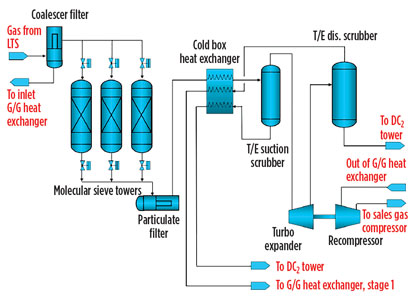
16 Natural gas processing is a complex process that consists of operations involving separation 17 of impurities and various non-methane hydrocarbons and fluids from the raw natural gas to 18 produce a pipeline quality dry natural gas. The process is also used to recover natural gas
Natural gas processing plants are used to purify the rawnatural gas extracted ... block flow diagram below is a generalized, typical configuration for the ...4 pages

Natural Gas Industry Process Flow Diagram. Create Process Flow Diagram examples like this template called Natural Gas Industry Process Flow Diagram that you can easily edit and customize in minutes. 1/16 EXAMPLES.

UOP Scope Delineations CONFIGURATION DIAGRAM Typical Cryogenic Gas Plant Project 28-MAY -2014 A Gas Processing Plant CFG.01 HMO Unit(s) Residue Gas to Sales Gas Pipeline Feed Gas Municipal Water Supply or Well Water Supply Fuel Gas Residue Gas Compression B a t t e r y L i m i t B a t t e r y L i m i t Stabilized Condensate Product Liquid ...

Apr 10, 2014 - A process flow diagram (PFD) is commonly used by engineers in natural gas processing plants, petrochemical and chemical plants, ...

xiv Plant Processing of Natural Gas J.C. Kuo (Chen Chuan J. Kuo) is a 34-year veteran of the gas process-ing, gas treating, and liquefied natural gas (LNG) industry. As a senior advisor for Chevron's Energy Technology Company, he has served as the Process Manager/ Process Lead for many projects, including the Wheatstone LNG, Gorgon
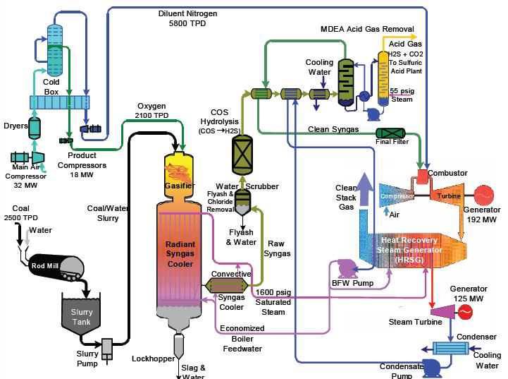
10.3.1. Methanol Plant Process Configurations. Figure 1 shows a simplified block flow diagram (BFD) of a methanol (MeOH) plant based on coal feedstock. Syngas from the gasifier is cooled by generating high pressure (HP) steam in the high temperature (HT) gas cooling system before being water quenched and scrubbed to remove fine particulates.
In Handbook of Liquefied Natural Gas, 2014. 7.4. LNG plant startup. The following is a general guideline for the startup for an LNG production plant. A generic C3MCR liquefaction train process flow diagram is shown in Figure 7-2. Startup of other liquefaction technologies may be slightly different.
A Process Flow Diagram (PFD) is a diagram which shows the relationships between the main components in a system. Process Flow Diagrams are widely used by ...

As a substitute for fossil natural gas, has many RNG potential uses. RNG can be used vehicle fuel, to as generate electricity, in thermal applications, or as a bio-product feedstock. RNG can be injected into natural gas transmission or distribution pipelines, or it can be used locally (i.e., at or near the site where the gas is created).

... natural gas purification system is mainly composed of the gas sweetening unit (GSU), dehydration unit (DU), sulfur recovery unit (SRU), tail ...

Natural Gas Feeds . Recycle Feeds . Oxidizer Feeds . Product Feeds . Fuel Burning Equipment . Thermal Oxidizer . Figure C -1: Ethane Cracker Process Flow Diagram . ... Polyethylene Plant A Process Flow Diagram Product Feeds Vent Streams Recycle Feeds Flare Feeds Fuel Burning Equipment PM Pollution Control Devices POLYMERIZATION PA-PE-202 ...

The reformed gas that has passed through a cooling process of the plant must now have its pressure boosted in order for the Methanol Synthesis reaction to occur. Compression is achieved in 3 stages, Low, Medium and High. All these compression stages are driven by one large and powerful gas fired Gas Turbine, that itself


0 Response to "40 natural gas plant process flow diagram"
Post a Comment