38 each class on an class diagram is represented by a(n) ____ in a relational database.
What can be said about the following relational database table? ... Each class on an class diagram is represented by a(n) ______ in a relational database? After you have downloaded the database, copy the file to the c:\linqtest5 folder. Overview. This walkthrough consists of six main tasks: Creating a LINQ to SQL solution in Visual Studio. Mapping a class to a database table. Designating properties on the class to represent database columns. Specifying the connection to the Northwind database.
Each class on an class diagram is represented by a(n) ____ in a relational database. a. attribute c. table b. row d. column.

Each class on an class diagram is represented by a(n) ____ in a relational database.
(Remember, N = many.) For each n-ary (> 2) relationship, create a new relation to represent the relationship. The primary key of the new relation is a combination of the primary keys of the participating entities that hold the N (many) side. In most cases of an n-ary relationship, all the participating entities hold a many side. Enhanced entity-relationship diagrams are advanced database diagrams very similar to regular ER diagrams which represent requirements and complexities of complex databases. These are very common relationships found in real entities. However, this kind of relationship was added later as an enhanced extension to the classical ER model. Types of UML Class Diagram Relationships ... It is a structural relationship that represents objects can be connected or associated with ...
Each class on an class diagram is represented by a(n) ____ in a relational database.. UML is the acronym for Unified Modeling Language; it is a general-purpose modeling language used when designing object-oriented systems. Entities are represented as class diagrams. Relationships are represented as associations between entities. The diagram shown below illustrates an ER diagram using the UML notation. In this article. Data in one table often relates to data in another table. For example, you might have a Teachers table and a Class table, and the Class table might have a lookup relation to the Teachers table to show which teacher teaches the class. You can use a lookup column to show data from the Teachers table. This is commonly referred to as a lookup column. A sequence diagram is structured in such a way that it represents a timeline which begins at the top and descends gradually to mark the sequence of interactions. Each object has a column and the messages exchanged between them are represented by arrows. A Quick Overview of the Various Parts of a Sequence Diagram. Lifeline Notation Use Case Diagram. As the most known diagram type of the behavioral UML types, Use case diagrams give a graphic overview of the actors involved in a system, different functions needed by those actors and how these different functions interact.. It's a great starting point for any project discussion because you can easily identify the main actors involved and the main processes of the system.
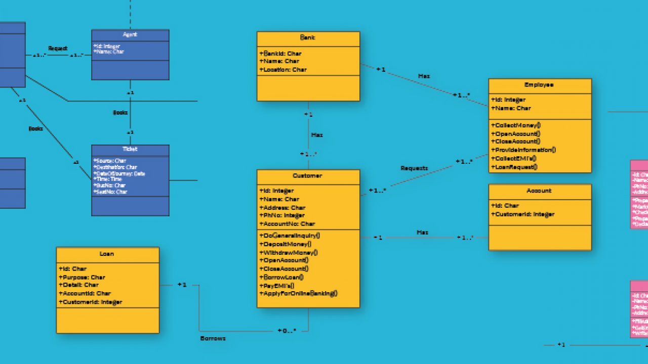
Those entities (1a, 1b, 1c, and 1d in the following diagram) are centralized by physical MDM to form a single record in the MDM database. That single record represents the golden record for that person, organization, object, or so on, where entity type 1 in the diagram represents the type of the information that is being mastered. Use case diagram is a behavioral UML diagram type and frequently used to analyze various systems. They enable you to visualize the different types of roles in a system and how those roles interact with the system. This use case diagram tutorial will cover the following topics and help you create use cases better. Importance of use case diagrams. Database Structure. A database is an organized collection of data. Instead of having all the data in a list with a random order, a database provides a structure to organize the data. One of the ... Class: A class is used to represent various objects. It is used to define the properties and operations of an object. In UML, we can also represent an abstract class. A class whose functionalities are not defined is called an abstract class. Any UML class diagram notations are generally expressed as below UML class diagrams example,
Each class on an class diagram is represented by a(n) ____ in a relational database. a. attribute c. table b. row d. column. C. Each class on an class diagram is represented by a(n) ____ in a relational database. . A UML Class Diagram showing First-cut design class diagram. The primary difference between the first-cut design class diagram and the final design class diagram is the addition of method signatures. Because class diagrams are used for a variety of purposes ... The total participation by entities is represented in E-R diagram as: A. Dashed line. B. Double line. C. Double rectangle. D. ... Below is a Relational Database Trivia Quiz! It is designed to help you understand how databases holding the same information are structured and maintained. ... Generic class because without this linked list is not ... An Entity Relationship Diagram (ERD) is a visual representation of different entities within a system and how they relate to each other. For example, the elements writer, novel, and a consumer may be described using ER diagrams the following way:
Relation Database Wikipedia
Each class on a class diagram is represented by a(n)_____in a relational database. table. A relational database table is in_____normal form if it has no ...
Wps Prenhall Com
Whereas a relational model uses a junction table to store row associations, a multidimensional model uses an intermediate measure group. Intermediate measure group is the term we use to refer to a table that maps members from different dimensions. Visually, a many-to-many dimensional relationship is not indicated in a cube diagram.

Databases Flashcards Quizlet
A table is a collection of related data held in a table format within a database. It consists of columns and rows. In relational databases, and flat file ...
Repository Its Ac Id
So the cardinality will be n to 1. It means that for one course there can be n students but for one student, there will be only one course. Using Sets, it can be represented as: In this case, each student is taking only 1 course but 1 course has been taken by many students. 3.
Er Diagram Representation
Rdbms MCQ Quiz & Online Test: Practice Below the Best RDBMS MCQ Questions, that check your basic knowledge of RDBMS. This RDBMS Test contains 25+ Best RDBMS Multiple Choice Questions. apart from this, you can also download below the RDBMS MCQ PDF, completely free.
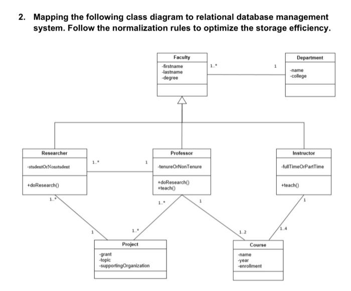
Solved 2 Mapping The Following Class Diagram To Relational Chegg Com
A Class in UML diagram is a blueprint used to create an object or set of objects. The Class defines what an object can do. It is a template to create various objects and implement their behavior in the system. A Class in UML is represented by a rectangle that includes rows with class names, attributes, and operations.

Foreign Key Column An Overview Sciencedirect Topics
Each class on an class diagram is represented by a(n) ____ in a relational database. a. Attribute b. Row c. Table d. Column.
Chapter 8 The Entity Relationship Data Model Database Design 2nd Edition
Each class on an class diagram is represented by a(n) ____ in a relational database. a. attribute c. table b. row d. column.
Mu Ac In
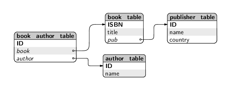
The ticket distributor waits for the new database from the ... 2–6 Draw a class diagram representing a book defined by the following ...
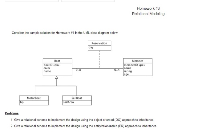
Solved Homework 3 Relational Modeling Consider The Sample Chegg Com
In a relational database, each entity has its own table. ... The statement “A sales rep's pay class functionally determines his or her pay rate” means that ...
Youth Cyber Dating Abuse A Meta Analysis Of Risk And Protective Factors Caridade Cyberpsychology Journal Of Psychosocial Research On Cyberspace
Let's move on to the three examples. I'll show these many-to-many relationships in ER diagrams drawn in the Vertabelo Database Modeler. Example 1: University Database. In this example, your task is to build a university database. You've just started, but you're already stuck.

Revision Chapter 3 4 Mock Test Ppt Video Online Download
ER diagrams can serve as reference documents once a database is in use. ... A(n) ____ is a generalized class of people, places, or things for which data is ...
Er Diagram Entity Relationship Diagram Model Dbms Example
Each class on an class diagram is represented by a(n) ____ in a relational database.. table. In a one-to-many association the primary key of the "many" ...

Java Chapter 12 Programming 2 Flashcards Quizlet
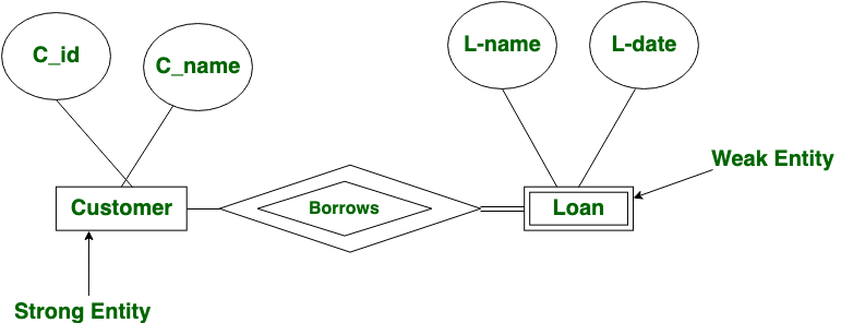
Strong entity is represented by a single rectangle. Weak entity is represented by a double rectangle. 4. Two strong entity's relationship is represented by a single diamond. While the relation between one strong and one weak entity is represented by a double diamond. 5. Strong entities have either total participation or not.
Fao Org
ER Model in DBMS stands for an Entity-Relationship model. The ER model is a high-level data model diagram. ER diagrams are a visual tool which is helpful to represent the ER model. ER diagrams in DBMS are blueprint of a database. Entity relationship diagram DBMS displays the relationships of entity set stored in a database.

Romi Sad Mar2019 Pdf
Each class on an class diagram is represented by a(n) ____ in a relational database.. Table. A(n) ____ is a field or set of fields stored in one table that ...

Data Modeling And Entity Relationship Diagram Erd
a_c-customer to accounts: (1,N) l_c-customer to loans: (0,2) loans-bank_branch to loan: (0,1000) Consider the ER diagram shown below for part of a BANK database. Each bank can have multiple branches, and each branch can have multiple accounts and loans. a. List the (nonweak) entity types in the ER diagram. Customer, Account, Loan, Bank
5 6 Databases
If you're a student taking database classes, make sure to create a free Academic account in Vertabelo, our online ER diagram drawing tool. Vertabelo allows you to draw logical and physical ER diagrams directly in your browser. It supports PostgreSQL, SQL Server, Oracle, MySQL, Google BigQuery, Amazon Redshift, and other relational databases.

Relational Database Wikipedia
A relational database table is in ____ normal form if every non-key field is ... Each class on an class diagram is represented by a(n) ____ in a relational ...

What Are The Different Types Of Relationships In Dbms
Generalization, Specialization and Aggregation in ER model are used for data abstraction in which abstraction mechanism is used to hide details of a set of objects. Generalization is the process of extracting common properties from a set of entities and create a generalized entity from it. It is a bottom-up approach in which two or more ...
Hierarchical Database Model Concise Guide To Hierarchical Data Model
Learn about relational databases, the basics of their structure and how they ... Each record assigns a value to each feature, making relationships between ...
Class Diagram Relationships In Uml Explained With Examples
Relational Model (RM) represents the database as a collection of relations. A relation is nothing but a table of values. Every row in the table represents a collection of related data values. These rows in the table denote a real-world entity or relationship. The table name and column names are helpful to interpret the meaning of values in each ...
1
Each class on an class diagram is represented by a(n) ____ in a relational database. a. attribute c. table b. row d. column.

Class Diagram Relationships Examples Relationships Uml Class Diagrams
The relationship type WORKS_ON (Figure 7.13) is of cardinality ratio M:N, because the mini world rule is that an employee can work on several projects and a project can have several employees. Cardinality ratios for binary relationships are represented on ER diagrams by displaying 1, M, and N on the diamonds as shown in Figure 7.2.
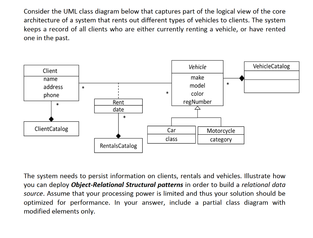
Solved Consider The Uml Class Diagram Below That Captures Chegg Com
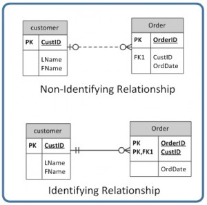
In the below ER Diagram, 'Payment' is the weak entity. 'Loan Payment' is the identifying relationship and 'Payment Number' is the partial key. Primary Key of the Loan along with the partial key would be used to identify the records. The existence of rooms is entirely dependent on the existence of a hotel. So room can be seen as the ...
Data Analysis In Mysql Operators Joins And More In Relational Databases By Craig Dickson Towards Data Science
A class diagram is a collection of classes similar to the one above. Relationships in Class Diagrams. Classes are interrelated to each other in specific ways. In particular, relationships in class diagrams include different types of logical connections. The following are such types of logical connections that are possible in UML: Association

Chapter 15 Web Object Oriented Database Development Ppt Video Online Download
Each class on an class diagram is represented by a(n) ____ in a relational database. a. attribute c. table b. row d. column.
1
When you need to create an ER diagram to document a database, it will be much easier using pre-made symbols and icons. This page gathers many useful symbols that often used in ER diagrams, Chen ERD, Express-G diagram, ORM diagram, Martin ERD and database model diagram. ER diagrams are best created with the use of proper and powerful diagram tools.
1
Types of UML Class Diagram Relationships ... It is a structural relationship that represents objects can be connected or associated with ...

What Is Class Diagram
Enhanced entity-relationship diagrams are advanced database diagrams very similar to regular ER diagrams which represent requirements and complexities of complex databases. These are very common relationships found in real entities. However, this kind of relationship was added later as an enhanced extension to the classical ER model.
What Is Link And Association Definition Types Of Association Association Class Binary Terms
(Remember, N = many.) For each n-ary (> 2) relationship, create a new relation to represent the relationship. The primary key of the new relation is a combination of the primary keys of the participating entities that hold the N (many) side. In most cases of an n-ary relationship, all the participating entities hold a many side.
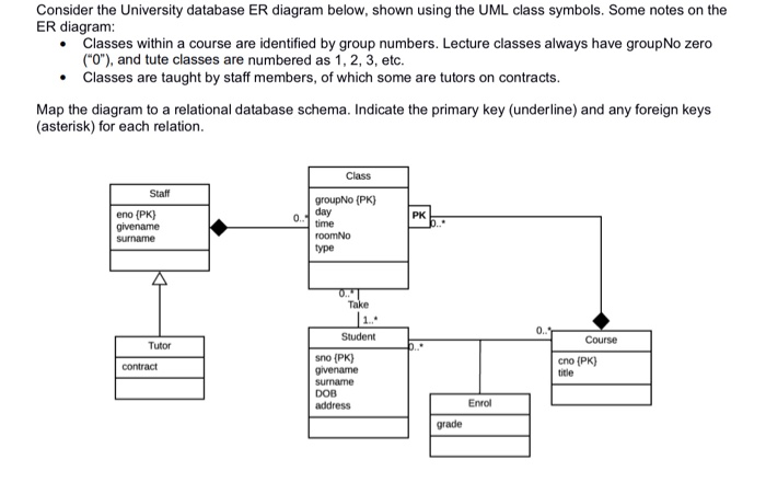
Solved Consider The University Database Er Diagram Below Chegg Com

Class Diagram Relationships Examples Relationships Uml Class Diagrams
Chapter 9 Integrity Rules And Constraints Database Design 2nd Edition
Weak Entity Set In Er Diagrams Geeksforgeeks

What Is Class Diagram
Solved Systen Analysis And Design Class Need Help With This Chegg Com
Er Diagram Representation
0 Response to "38 each class on an class diagram is represented by a(n) ____ in a relational database."
Post a Comment