39 air handling unit diagram
PDF Air Handling Units - Ferroli a= Air flow rate (m 3/h) s f= Front surface of the coil (m 2) (refer to Table 9 on p. 13) T 1= Dry bulb air temperature at inlet (°C) T 2= Dry bulb air temperature at outlet (°C) T 2F= Apparent dry bulb air temperature at outlet (°C) J 1= Isoenthalpic condition of inlet air (kcal/kg) J 2= Isoenthalpic condition of outlet air (kcal/kg) T PDF AHU Air Handling Unit Fundamentals - 123seminarsonly.com HVAC Air Systems • HVAC air systems are made up of: -AHU -Air handling units -Dampers -Coils and Valves -Fans -Distribution ducts and terminal boxes -Pumps and Plumbing -Control devices and control loops -Unitary equipment: fan coils, perimeter radiation, unit ventilators, unit heaters, etc.
Air Handling Units Explained - Diagrams, Types of AHU In this module, we will look at how to inspect, clean, and replace the air filter in an air handling unit (AHU).

Air handling unit diagram
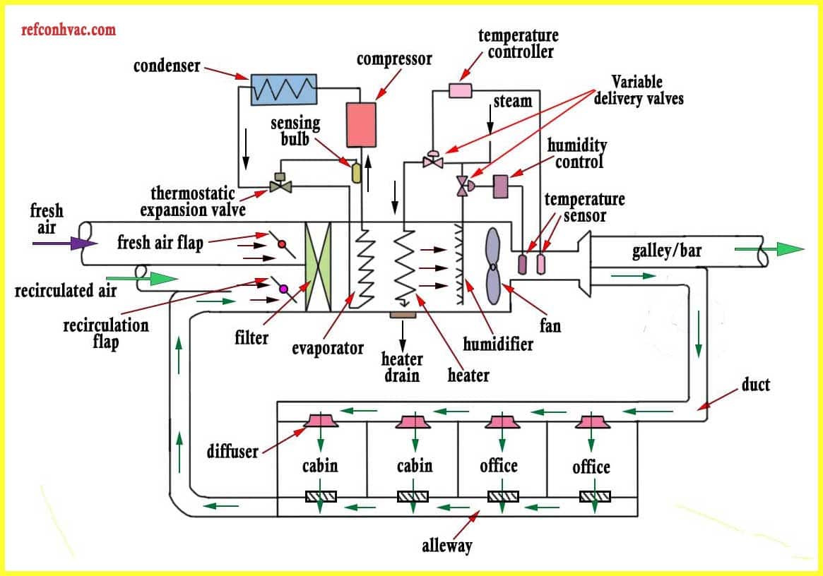
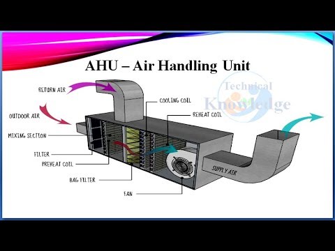
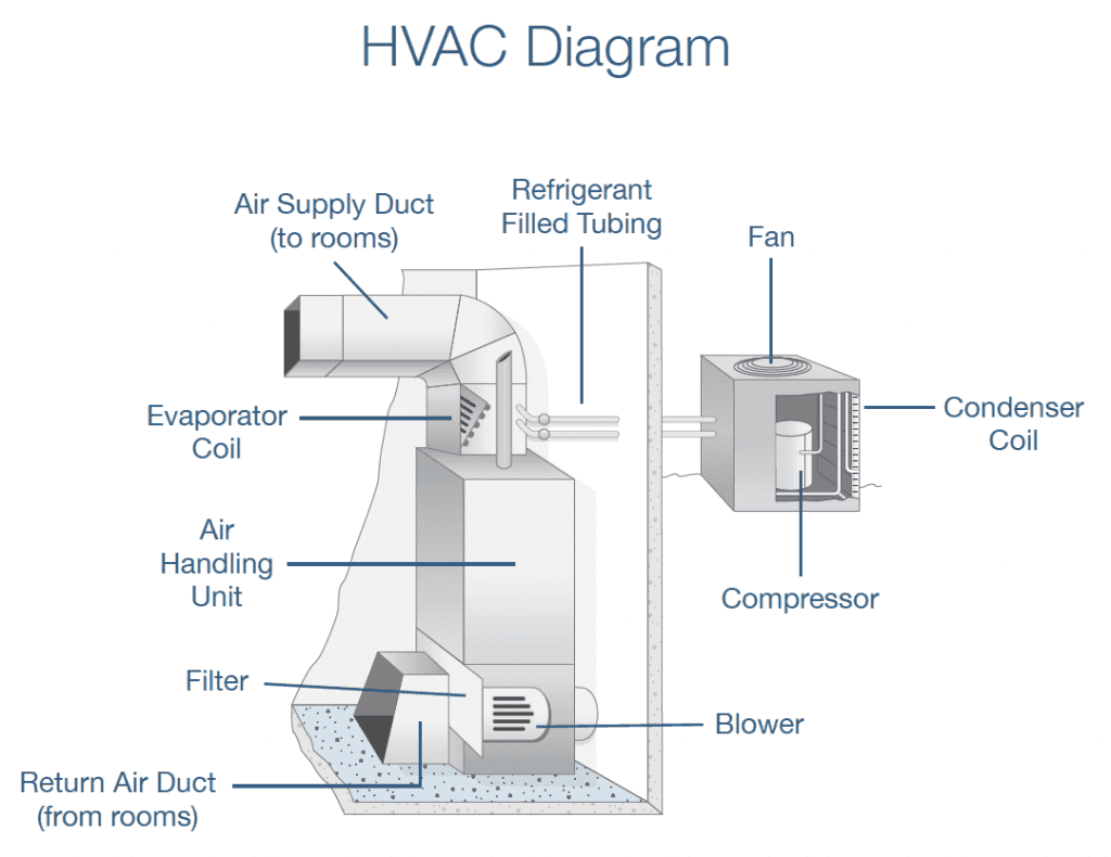
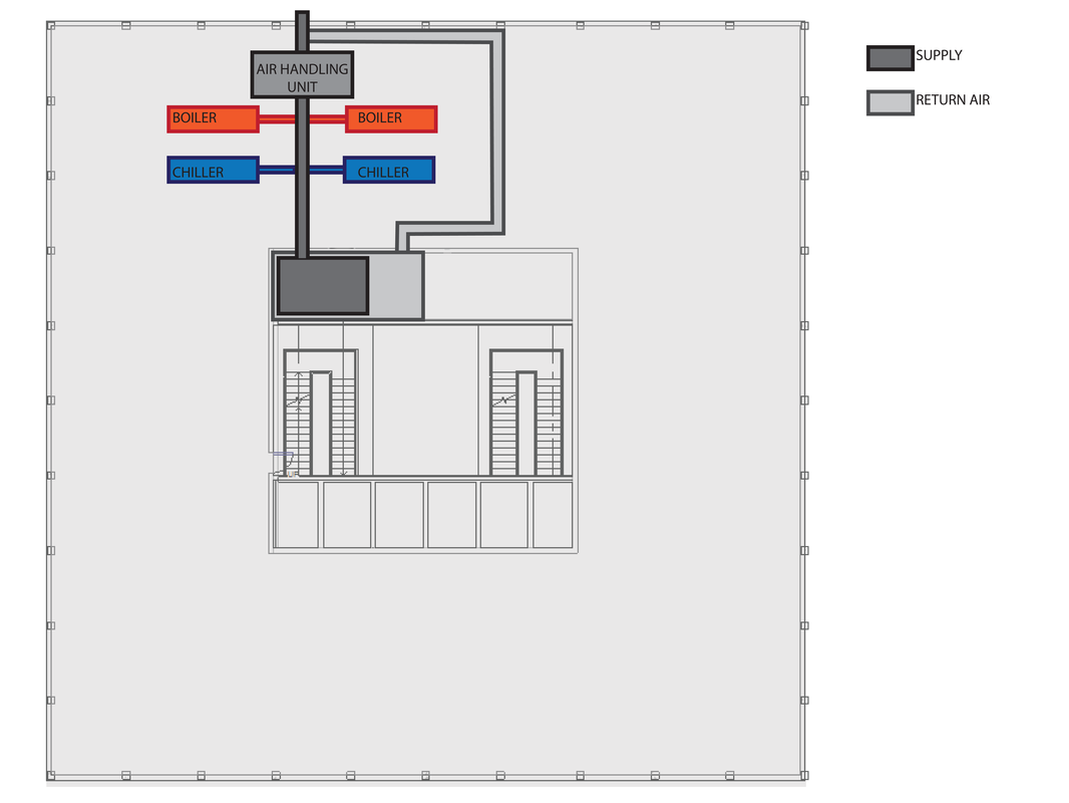
What is air handling Unit | Diagram , Types of Air ... What is air handling Unit | Diagram , Types of Air Handling Unit Air handling Unit Definition : The definition of air handling unit from ANSI/AHRI Standard 430-2009 states that it is "A factory-made encased assembly consisting of a fan or fans and other necessary equipment to perform one or more of the functions of circulating, cleaning, heating, cooling, humidifying, dehumidifying and ... What is Air Handling Unit (AHU)? Diagram, Parts & Working ... Therefore, the pressure is positive on the discharge side of the fan and negative on the suction side. Fig. 1: Air flow diagram Principles of Air Handling Unit (AHU) Air should be distributed in the room, so that, the required temperature, humidity and air velocity are maintained in the occupied zone of about 1.8 m above the floor. Functional Block Diagram | Air handler- HVAC plan | | Ahu ... Functional Block Diagram This HVAC plan sample shows the air handler layout on the floor plan. "An air handler, or air handling unit (often abbreviated to AHU), is a device used to condition and circulate air as part of a heating, ventilating, and air-conditioning (HVAC) system.
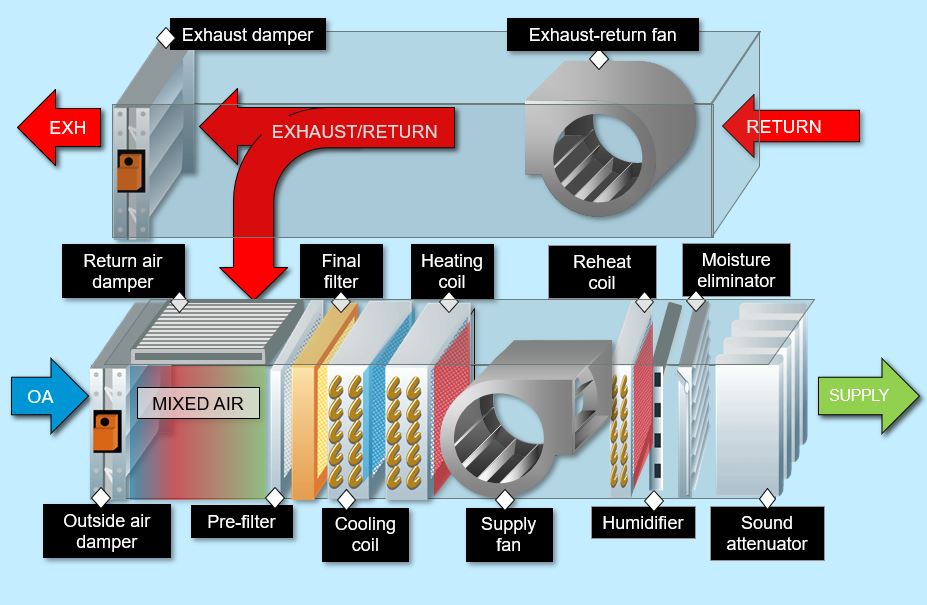
Air handling unit diagram. Ventilation system layout | Air handler- HVAC plan | HVAC ... "An air handler, or air handling unit (often abbreviated to AHU), is a device used to condition and circulate air as part of a heating, ventilating, and air-conditioning (HVAC) system. An air handler is usually a large metal box containing a blower, heating or cooling elements, filter racks or chambers, sound attenuators, and dampers. PDF HVAC Air Handling Unit Design Considerations An air handling unit often abbreviated as AHU, is a factory fabricated assembly consisting of fan, heating and/or cooling coils, filters, dampers and other necessary equipment to perform one or more of the following functions of circulating, cleaning, heating, cooling, PDF Development of Psychrometric diagram for the energy ... Air Handling Units (AHU), Energy efficiency, Psychrometric diagram 1 INTRODUCTION The residential buildings represent about 40% - 50% of the total energy consumption and the major part of this consumption is used for Air Handling Units (AHU) to prepare the thermal comfort (Council 2013). Air Handling Unit Diagram manufacturers, China Air ... Import quality Air Handling Unit Diagram supplied by experienced manufacturers at Global Sources. We use cookies to give you the best possible experience on our website. For more details including how to change your cookie settings, please read our Cookie Policy .
Air Handler Wiring Diagram - Wirings Diagram Air Handler Wiring Diagram - air handler wiring diagram, air handler wiring diagram goodman, air handler wiring schematic, Every electric structure is composed of various unique pieces. Each part ought to be set and connected with other parts in specific way. If not, the arrangement won't work as it should be. Air Handling Units (AHU): HVAC Series Part I Air Handling Unit Meaning. An air handler, or air handling unit (often abbreviated to AHU ), is a device used to condition and circulate air as part of a commercial or industrial HVAC system. Usually, an air handler is a large metal box containing a blower, heating and/or cooling elements, filter racks or chambers, sound attenuators, and dampers. PDF Air handler installation manual the unit wiring diagram. 8 Horizontal right is the default factory configuration for the units. Conversion to Horizontal: A vertical upflow unit may be converted to horizontal left by removing indoor coil assembly and reinstalling coil as shown for left hand air supply. And reinstall coil in unit as shown for left hand air supply. Lennox Air Handler Wiring Diagram General. The Lennox Elite® Series CBX32M air handler units are designed for installation with a matched remote outdoor unit that. How to Wire an Air Conditioner for Control - 5 Wires - The diagram below includes the typical control wiring for a conventional air conditioning system.Air Handling Unit (AHU): a device used to condition and ...
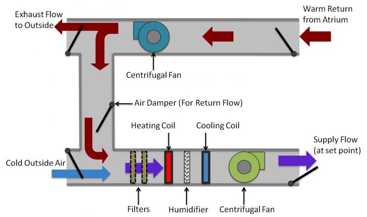
RoofPak Air Handling Units - Daikin Applied 1. Unit(s) surrounded by screens or solid walls must have no overhead obstructions over any part of the unit. 2. The following restrictions must be observed for overhead obstructions above the air handler section (see Figure 17): a. There must be no overhead obstructions above the furnace flue, or within 9" (229 mm) of the flue box. b. Rheem Rhll Air Handler Wiring Diagram - IOT Wiring Diagram Rheem Ruud Hvac Age Manuals Parts Lists Wiring Diagrams Free Pdf S. 7 Kw Rheem Rxbh Electric Strip Heater With Circuit Breaker. 92 20921 32 Rev 20 Rhll Rhsl Air Handler Installation Instructions. Rpql043jez Rhllhm4821ja 3 5 Ton 15 Seer Ruud Heat Pump System. Untitled. Schematic diagram of an air-handling unit | Download ... Schematic diagram of an air-handling unit. The controllers of air-handling units (AHU) should exploit split-range sequencing control strategies to determine the most economic way to use the AHU ... PDF Introduction: Hvac Basics Starting at point A on the diagram above, return air passes through the filters on the system and is drawn into the supply fan. The air is then pushed into the dual duct section of the unit. It will now separate into two ducts, one that will handle the heating functions and one that will handle the cooling functions:

What is air handling Unit | Diagram , Types of Air Handling Unit
Air Handling Unit Diagram - Air Handling Unit Diagram ... Air Handling Unit Diagram - Air Handling Unit Diagram : Solved 5 A Draw Through Air Handling Unit Ahu Will Be Chegg Com .... Don't let the cool air from your window unit seep out through a bad seal. Copper tubing cutters wire cutter moving dolly copper tubing copper conn. This will obviously make it harder for t.
Air Handling Unit Maintenance That Gets Results | RasMech
PDF Variable Air Volume Air Handling Unit With Minimum Outside ... VARIABLE AIR VOLUME AIR HANDLING UNIT WITH MINIMUM OUTSIDE AIR CONTROL DIAGRAM EXHAUST AIR D-3 D-2 OUTSIDE PRE- FILTER AIR D-1 COIL PREHEAT COIL COOLING LOCATE SENSOR OUTSIDE UNDER SHIELD MPS V-2 V-1 CHR CHS RETURN FAN SUPPLY FAN AFMD RETURN AIR FINAL FILTER AFMD V-3 LPS V-4 STEAM HUMIDIFIER SUPPLY AIR TO TERMINAL UNIT 10' MIN. [3000mm]
Air handling unit.
Schematic diagram of a typical AHU system. | Download ... ... typical air handling unit (AHU) of an HVAC system supplies conditioned air to building zones. Fig. 1 illustrates the schematic diagram of such an AHU system. The supply air is at a specific...
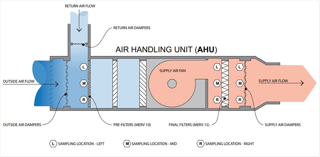
Identification of SARS-CoV-2 RNA in healthcare HVAC units
PDF FXTQ-PA Air Handling Unit - Daikin AC Air Handling Unit Notes: 1 Nominal cooling capacities are based on the following conditions: Return air temperature: 80°FDB(27°CDB), 67°FWB(19.4°CWB) Outdoor temperature: 95°FDB (35°C) Equivalent ref. piping: 25ft (7.5 m) (Horizontal) 2 Nominal heating capacities are based on the following conditions: Return air temperature: 70°FDB (21°C)
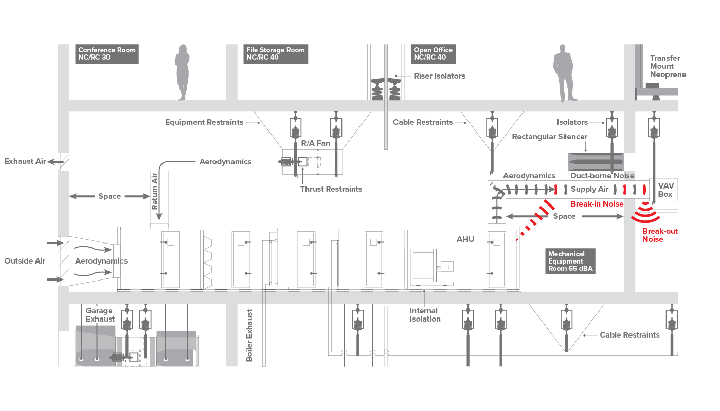
Air Handling Units - Vibro-Acoustics - Noise Control
PDF Dometic Air Handler Wiring Diagrams Manual 6 C 010001 A AT6- 6HV(Z) with COS Air Handler diagram 7 C 010002 AT4F(Z) with COS Air Handler diagram 8 C 01000 AT6-18F(Z) with COS Air Handler diagram ... UNIT HAS ELECTRIC HEAT. 115-230/50-60/1 #12 POWER SUPPLY GND L1 N/L2 ELECTRICAL BOX DISPLAY PANEL OPTIONAL ALT. AIR SENSOR WATER INLET SENSOR HANDLER CONTROLLER.
Air handling systems new
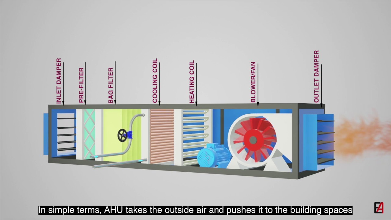
Air Handling Units Explained - The Engineering Mindset Air Handling Units. In this article we'll be learning how Air Handling units, or AHU's, work. We'll look at different examples of typical AHU's along with animations for components such as dampers, heating and cooling coils, heat wheels, humidifiers, run around coils, heat exchangers and more, to help you learn HVAC engineering.

Air Handling Unit Design and Working Explained #AirHandlingUnit #AHU
What is an air handling unit (AHU)? - AirTecnics An air handling unit, commonly called an AHU, is the composition of elements mounted in large, accessible box-shaped units called modules, which house the appropriate ventilation requirements for purifying, air-conditioning or renewing the indoor air in a building or premises.

Air Handling Unit | HVAC | Business | LG Global
Air Handling Unit Diagram Wholesale, Air Handling Unit ... Source wholesale Air Handling Unit Diagram from 78 reliable wholesalers. Large selection of quality wholesale Air Handling Unit Diagram products in China.

Schematic diagram of air handling unit in both buildings with ...
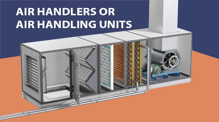
What are Air handlers or Air Handling Units or AHU ... Air Handling Unit Parts I Simple Block Diagram AHU Casing & Base Frame Description The casing is the outer most part of the air handling unit. It is basically housing where all the parts are installed. Air handler unit casing is factory assembled, modular, single skinned, or double skinned with insulation.
9 Factors to Consider Before Installing AHU - refconhvac.com
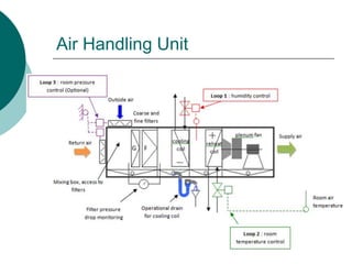
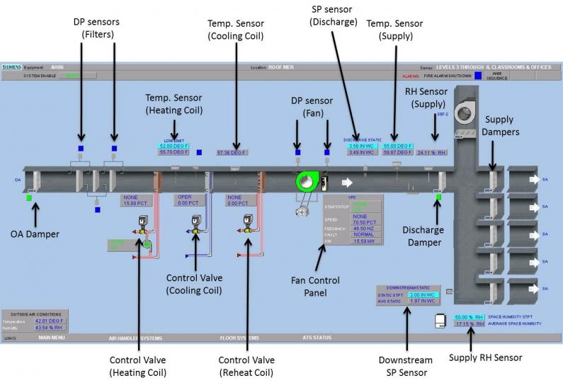
PDF Air Handling Unit (AHU) Controller Technical Bulletin The Johnson Controls Air Handling Unit (AHU) Controller is a complete digital control system for most common air handling configurations, including single zone, variable air volume, multi-zone, and dual duct. You may use the AHU as a standalone controller or connected to a FMS. When connected to the FMS, the AHU provides all point and control
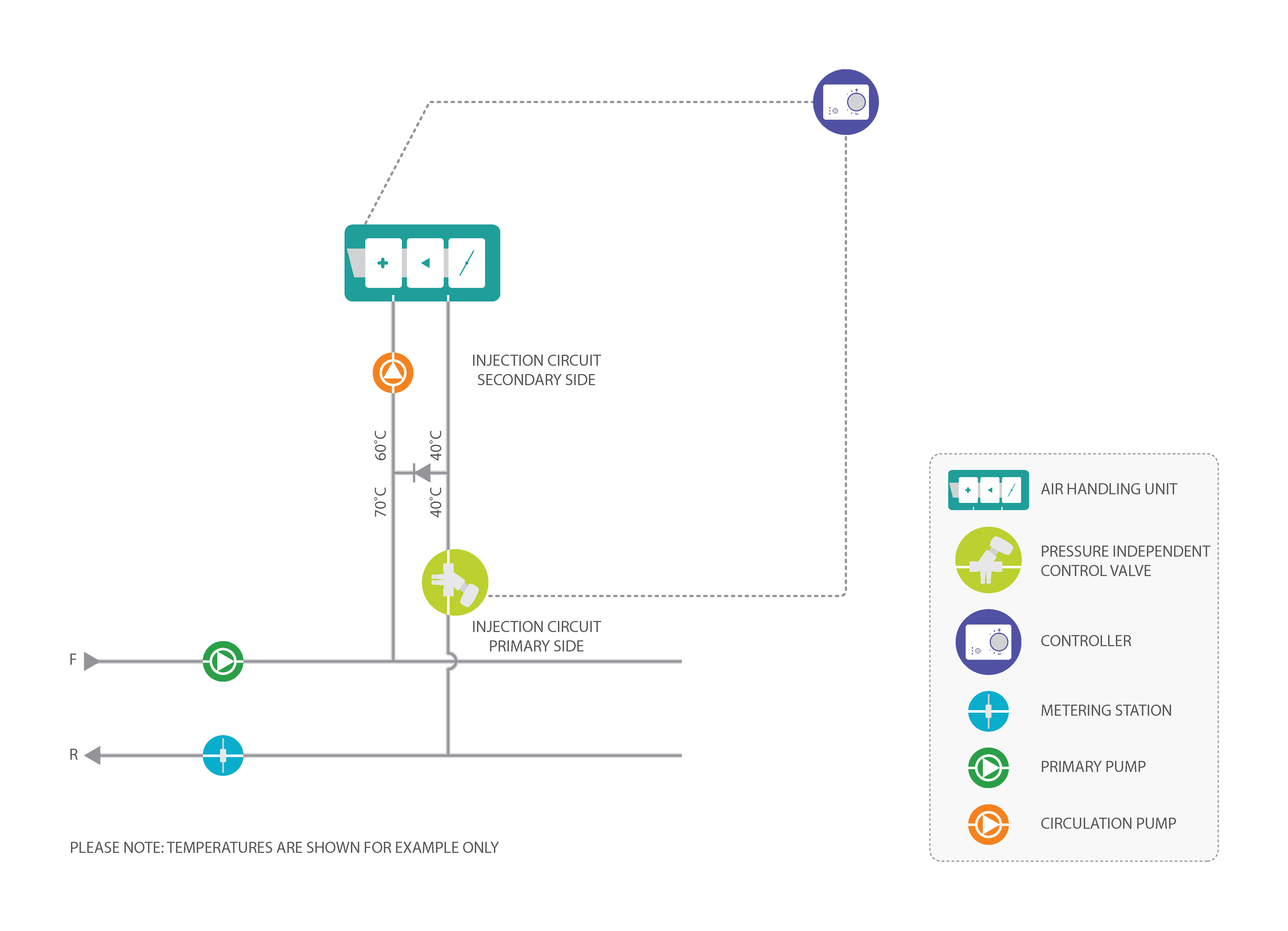
Air Handling Unit - PICV injection circuit
Air Handling Unit - Air Conditioning Systems An air handling unit where (1) is the supply air, (2) fan section, (3) vibration isolator, (4) cooling coil, (5) filter and (6) mixed air duct. Components of Air Handling Unit. Here are some of the air handling unit components that may be contained in the equipment.

Air Handling Unit, Air Handlers, Air Handling Unit System ...
Functional Block Diagram | Air handler- HVAC plan | | Ahu ... Functional Block Diagram This HVAC plan sample shows the air handler layout on the floor plan. "An air handler, or air handling unit (often abbreviated to AHU), is a device used to condition and circulate air as part of a heating, ventilating, and air-conditioning (HVAC) system.

Air Handling Unit Vector Images (31)
What is Air Handling Unit (AHU)? Diagram, Parts & Working ... Therefore, the pressure is positive on the discharge side of the fan and negative on the suction side. Fig. 1: Air flow diagram Principles of Air Handling Unit (AHU) Air should be distributed in the room, so that, the required temperature, humidity and air velocity are maintained in the occupied zone of about 1.8 m above the floor.
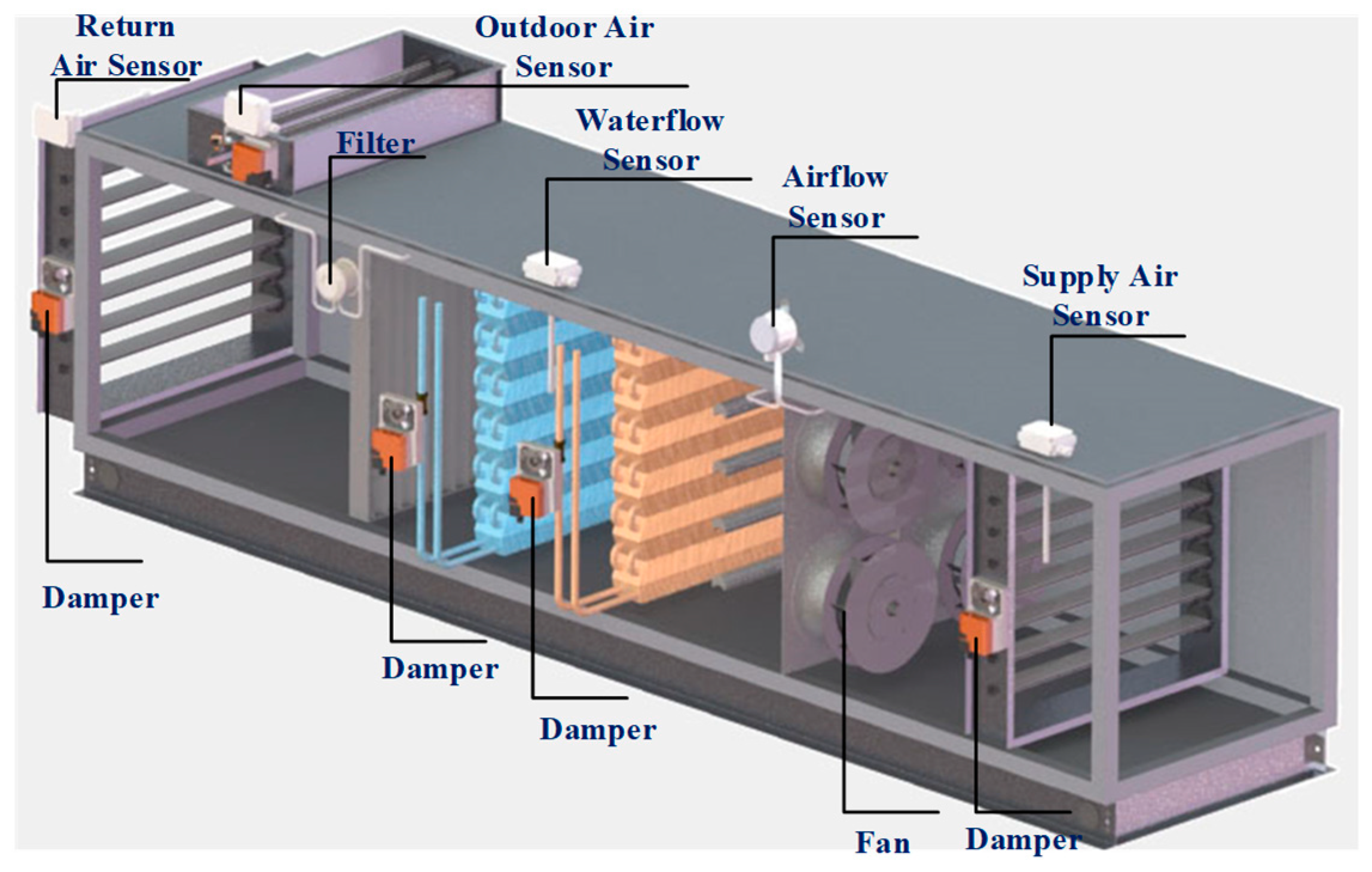
Sensors | Free Full-Text | An Online Data-Driven Fault ...
What is air handling Unit | Diagram , Types of Air ... What is air handling Unit | Diagram , Types of Air Handling Unit Air handling Unit Definition : The definition of air handling unit from ANSI/AHRI Standard 430-2009 states that it is "A factory-made encased assembly consisting of a fan or fans and other necessary equipment to perform one or more of the functions of circulating, cleaning, heating, cooling, humidifying, dehumidifying and ...

Central Air Conditioning: Systems and Applications | IntechOpen
What is the main difference between TFA and AHU in HVAC? - Quora
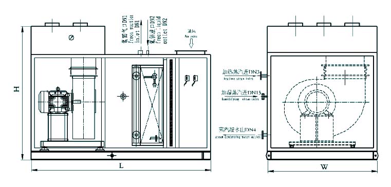
TMU Marine Direct Air Handling Unit Supplier, China Marine ...

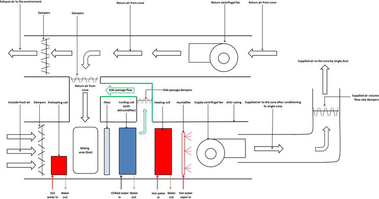
Schematic of a typical draw-through commercial air-handling ...
AIR HANDLING UNITS
CU Faculty
The general structure of the Air handling unit (AHU) used in ...

Schematic diagram of an air handling unit | Download ...

Figure 1 from Cooling output optimization of an air handling ...
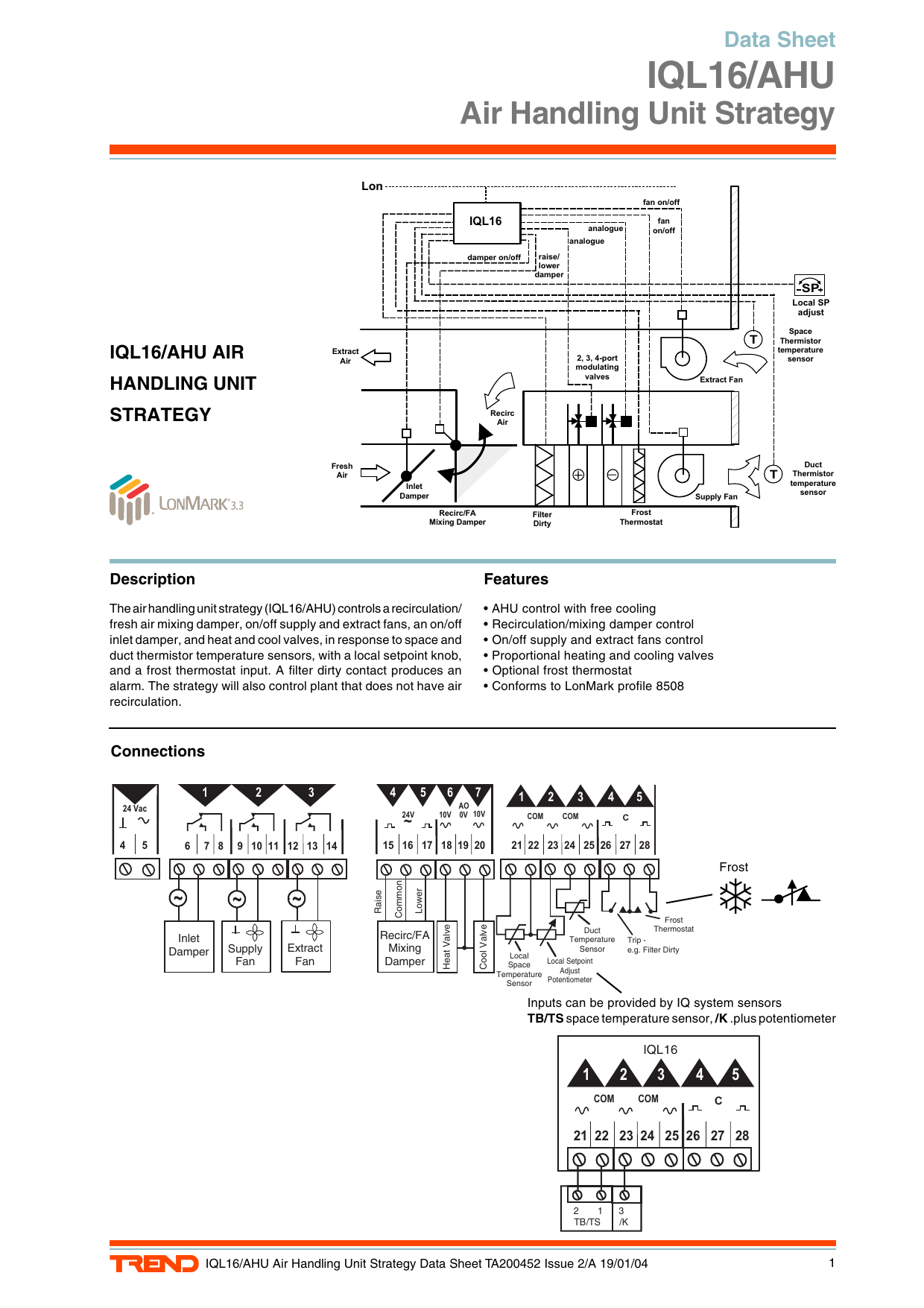
IQL16/AHU Air Handling Unit Strategy Data Sheet | Manualzz

SINGLE ZONE AIR HANDLING UNIT (AHU) BASIC AND TUTORIALS | ALL ...
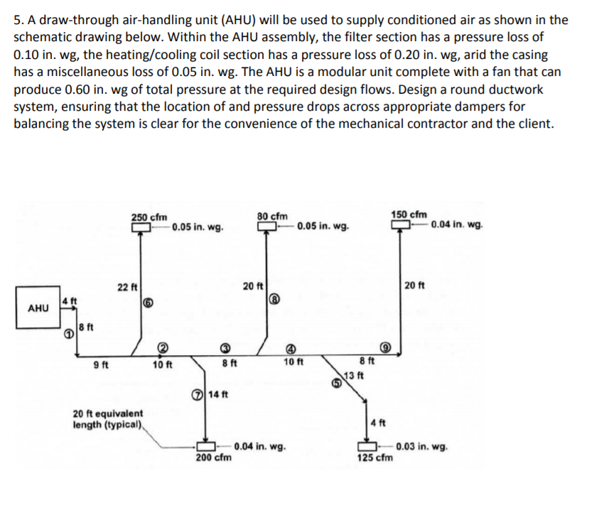
Solved 5. A draw-through air-handling unit (AHU) will be ...
Central Air Conditioning: Systems and Applications | IntechOpen
Air Handling Unit (AHU) Fundamentals with Cooling Principle and its components
What is Air Handling Unit of (Part of HVAC) How does it work ...
HVAC Replacement Cost | Standard Heating & Air Conditioning
HVAC Single Line Diagram - AE - 391: AE Design II - Winter 2015

Air Handling Units & Variable Flow - ProBalance

CU Faculty
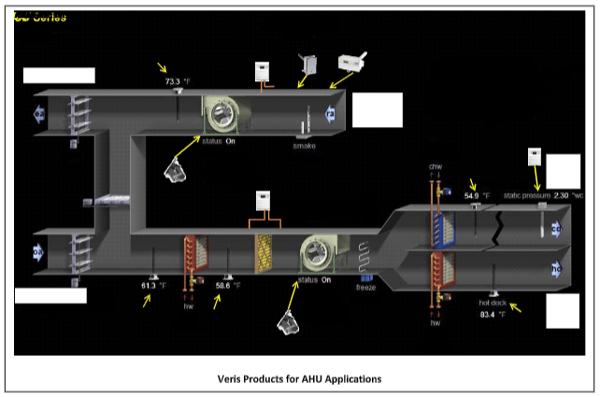
Air Handling Units (AHU): HVAC Series Part I
What are Air handlers or Air Handling Units or AHU ...

EB Air MODPAK Air Handling Unit (AHU) System - Air Handlers

Air Conditioning System: Air Conditioning System Ahu
Annex 2
CU Faculty
0 Response to "39 air handling unit diagram"
Post a Comment