40 ballast resistor wiring diagram
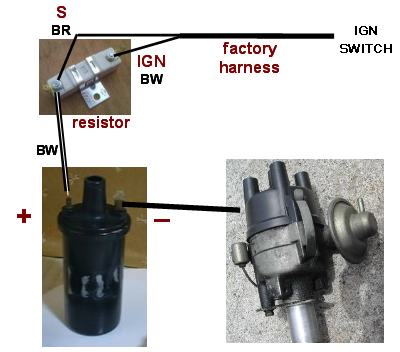
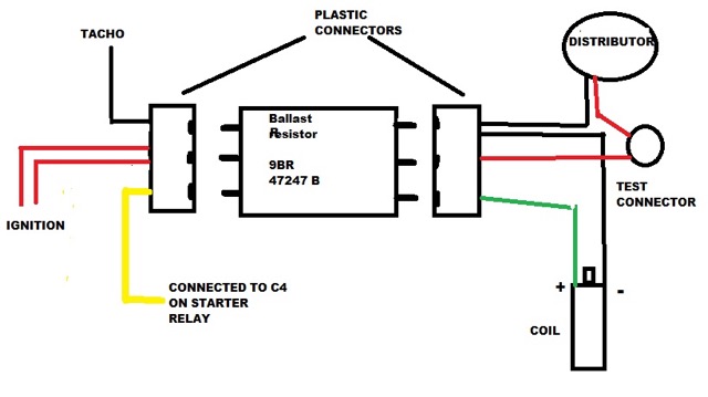
Ballast resistor wiring | Norton Owners Club You need to put the white or blue/white ignition wire direct to the l/h side of the ballast resistor (thats the squiggle) and not straight to the coil. Then using another piece of wire (preferably the same colour), run that from the r/h ballast connector to the -ve r/h coil. The black/white points wire then connects to the +ve r/h coil. › what-is-two-way-switch-wiringWhat is Two Way Switch Wiring : Circuit Diagram ... - ElProCus What is Two Way Switch Wiring : Circuit Diagram & Its Working A switch is an electrical device that controls the flow of current in a circuit. Every electronic and electrical application uses at least one switch to perform on and off operation of the device.
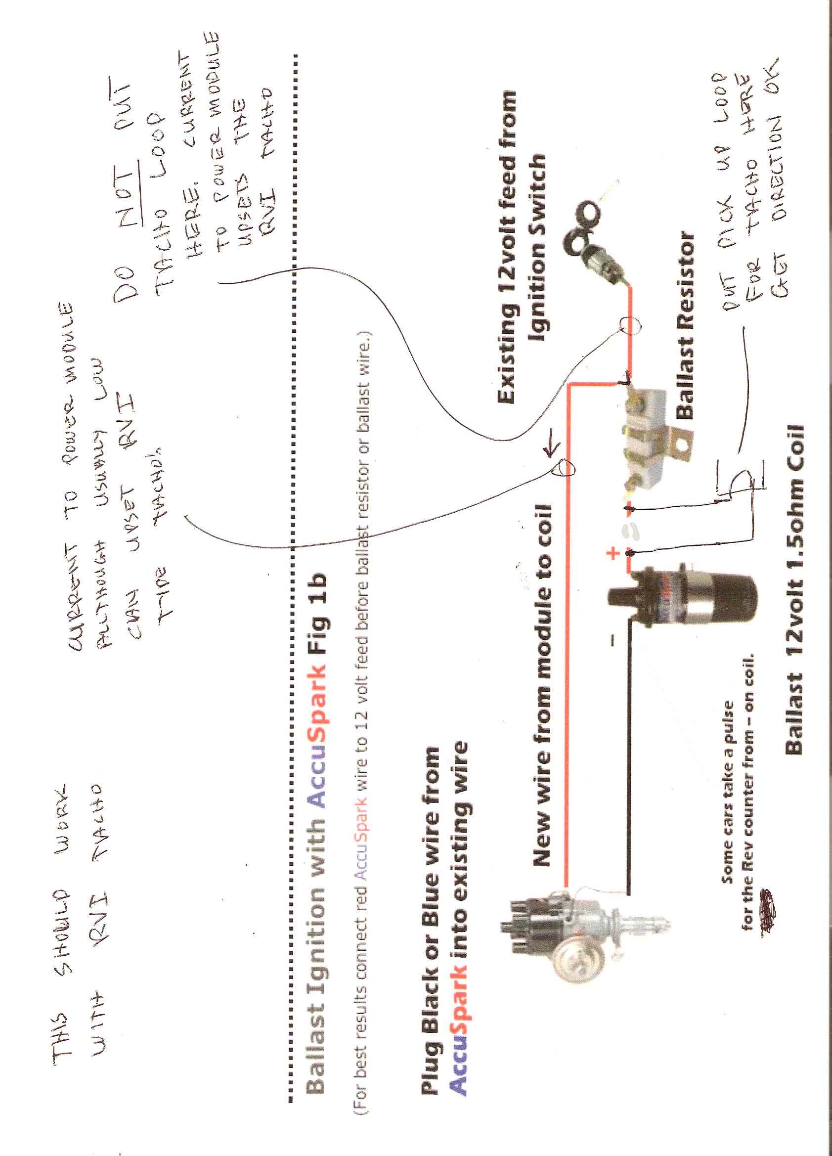
Technical - Please help ballast resistor wiring ignition ... I have uploaded picture of a wiring setup found when searching for ballast resistor wiring." That should work just fine. Basically start directly to coil for full 12 volt to start, run goes through the ballast resistor to cut down the voltage to the coil when the engine is running to take the load off of the points.
Ballast resistor wiring diagram
How To Read A Ballast Wiring Diagram - Cadician's Blog Ignition Coil Ballast Resistor Wiring Diagram Another Blog About - How To Read A Ballast Wiring Diagram. Wiring Diagram will come with a number of easy to stick to Wiring Diagram Guidelines. It really is meant to help all the typical consumer in creating a correct method. These directions will be easy to understand and use. Ballast Resistor Wiring Diagram Points - Wiring Sample Ballast Resistor Wiring Diagram Points. In a points type ignition the ballast resistor would help to keep the spark down and the coil from being burned up too quickly. Connect one side of the ballast resistor to the positive side of the coil. Diagram attached for wiring of points dizzy and coil with ballast resistor. 1959 Ford F100 Ballast Resistor Wiring Diagram Pertronix wiring diagram in addition chevy ballast resistor wiring diagram together with 6 0 engine cooling diagram html furthermore mustang voltage regulator wiring diagram also 92 f engine diagram moreover toyota auris fuse box location moreover club car ignition wiring diagram in addition ford msd ignition wiring diagram together. Find great ...
Ballast resistor wiring diagram. PDF Mopar Performance Electronic Ignition Kit Instructions 9. Route the blue wire to the ballast resistor. Avoid the exhaust manifolds and sharp edges, follow existing wiring harnesses if possible. 10. Disconnect the wires from both ends of the original ballast resistor. Remove the old ballast resistor and install the new ballast resistor in its place. Do not reconnect the wires. 11. ballast resistor wiring diagram | For A Bodies Only Mopar ... Here is a copy of the wiring diagram on MyMopar.com for a 75 Dart. Becareful of the 73 and 74 diagrams as they have an extra wire in the circuit from the ballast resistor to voltage regulator (brown wires) that will result in a constant 12 volts to the coil. 1976 F150 Ballast Resistor Wiring Diagram The ballast resistor get's installed on the wire from the ignition switch to the positive side of the ignition coil and it's the wire that is hot when the key is on run not start. the start coil wire should still have 12 volts. One second and I'll pull up the wiring diagram. Ford Ignition Wiring Diagram - wiring diagram plymouth reliant ... Ford Ballast Resistor Wiring Diagram Pictures - Wiring ... Ford Ballast Resistor Wiring Diagram. Print the wiring diagram off plus use highlighters to trace the signal. When you make use of your finger or perhaps the actual circuit with your eyes, it is easy to mistrace the circuit. 1 trick that We 2 to printing a similar wiring plan off twice.
Ballast resister | Team Camaro Tech The resistor, or resistor wire, is connected in series with the main power to the coil. With the ignition switch "on" the voltage is reduced to the coil and points. You have to use a coil that is designed to "use external resistor" only. (usually says this on the coil.) A separate wire from the starter gives the coil full voltage only for starting. › electrical-diagramsElectrical diagrams for Chrysler, Dodge, and Plymouth cars This wiring diagram is for the 1980 and later four pin ignition module. If you have an ignition harness with five wires, just don’t connect the dark green wire that would go to pin 3. I Installed a Jacobs computer ignition, and it doesn’t require a ballast resistor. Ballast Wiring Diagram - Wiring Diagram ballast wiring diagram - You will need a comprehensive, professional, and easy to comprehend Wiring Diagram. With such an illustrative guide, you will be able to troubleshoot, avoid, and complete your projects easily. Not only will it assist you to attain your desired outcomes quicker, but in addition make the complete procedure simpler for everybody. ballast resistor wiring diagram - Wiring Diagram Ballast Resistor Wiring Diagram. By | March 10, 2021. 0 Comment. No brainer wiring question ballast resistor bmw 2002 and other 02 faq ignition troubleshooting accuspark diagrams igniter with painless ih8mud forum heavy duty external for coils points electronic systems tech wiki coil datsun 1200 club chevy tri five bypassing a bos only mopar ...
Ballast Resistor - Rolls-Royce and Bentley Forums Don't bypass the ballast resistor, if you do that you'll overstress the coil. If you look in those diagrams you'll see that +12V is on B and Coil+ is on F. Between B & F is a resistance of about 2 Ohms, whilst cranking the starter 12V is applied to C and this has about 1 Ohm between C & F. Ballast Resistor wiring for 1977 Mgb - MGB Register Forum The ballast resistor is really a resistive wire. Disconnect the new ballast resistor and wiring put things back to original. Use a mulimeter and connect it to the + side of the coil (White/light green wires) and ground. Turn on the ignition and measure the voltage. This should be around 7v.If nothing the problem is probably with the ballast ... How the Ballast Resistor Works - YouTube This Video explains how the Ballast Resistor Works.For additional How-to Tutorials Visit our Website: › Manuals › 30021Wire Harness Installation Instructions - Painless Wiring 6 4.0 TOOLS NEEDED In addition to your regular tools, you will need, at least, the following tools: Crimping Tool Note: Use a quality tool to avoid over-crimping. Wire Stripper
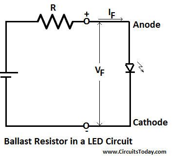
Ballast Resistor - Working, Uses, Applications and Types
› pub › mediaWiring Kit Instructions - American Autowire to the distributor, as in a GM HEI distributor, to a ballast resistor as in a points type distributor, or to the ignition power source for an aftermarket ignition module such as an MSD module. See the installation instructions for the type of distributor you are using for specific connection requirements. 6. Select the white Wiper feed wire (93).
1979 Mercedes 450SL ballast resistors | Mercedes-Benz Forum
Ballast Resistor By Pass Chrysler Valiant | For A Bodies ... Just wondering if somebody could help with my ballast resistor bypass on how to wire it correctly?. I live in Australia, this is a Chrysler Valiant VH series 1972 wiring diagram supplied. I have a 1 wire altenator in the system now and a crane H I 6 ignition system. I have bypassed the resistor with 1 wire across where the resistor originally ran,
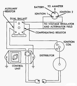
Dave's Place - Dodge Electronic Ignition
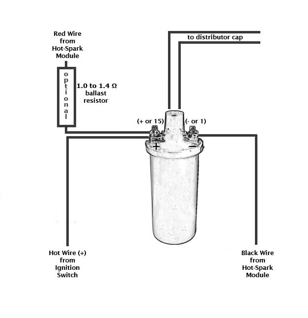
How do I Wire a Ballast Resistor & Coil? | It Still Runs Step 3. Cut a piece of wire long enough to reach from the other terminal of the ballast resistor to the "Bat", "+" or "B+" terminal of the coil. Strip 1/2 inch of insulation from each end of this wire and crimp a connector onto each end. Connect the wire to the unused terminal of the ballast resistor and to the previously identified terminal of ...

No brainer wiring question - Ballast resistor - BMW 2002 and ...
Wiring Diagram Ballast Resistor Ignition Coil - Wiring Diagram Diagram attached for wiring of points dizzy and coil with ballast resistor. This simple system is easy for even the novice mechanic to wire. A resistor that has the property of increasing in resistance as current flowing through it increases and decreasing in resistance as current decreases. Discussion in 1960 1966 started by ol betsy dec 20 2006.
Technical - Please help ballast resistor wiring ignition ...
Ballast Wiring - Electrical 101 Instant start ballasts can only be wired in parallel according to the diagram on the ballast. Changing the wiring on a fluorescent light fixture from rapid start to instant start, involves changing the wiring from series to parallel. 1 Lamp Rapid Start Ballast Diagram.

Is there a 67 911 engine compartment wiring diagram online?
Ignition Coil Ballast Resistor Wiring Diagram | Fuse Box ... Description: Ignition Coil Ballast Resistor Wiring Diagram with Ignition Coil Ballast Resistor Wiring Diagram, image size 609 X 360 px, and to view image details please click the image. Here is a picture gallery about ignition coil ballast resistor wiring diagram complete with the description of the image, please find the image you need.
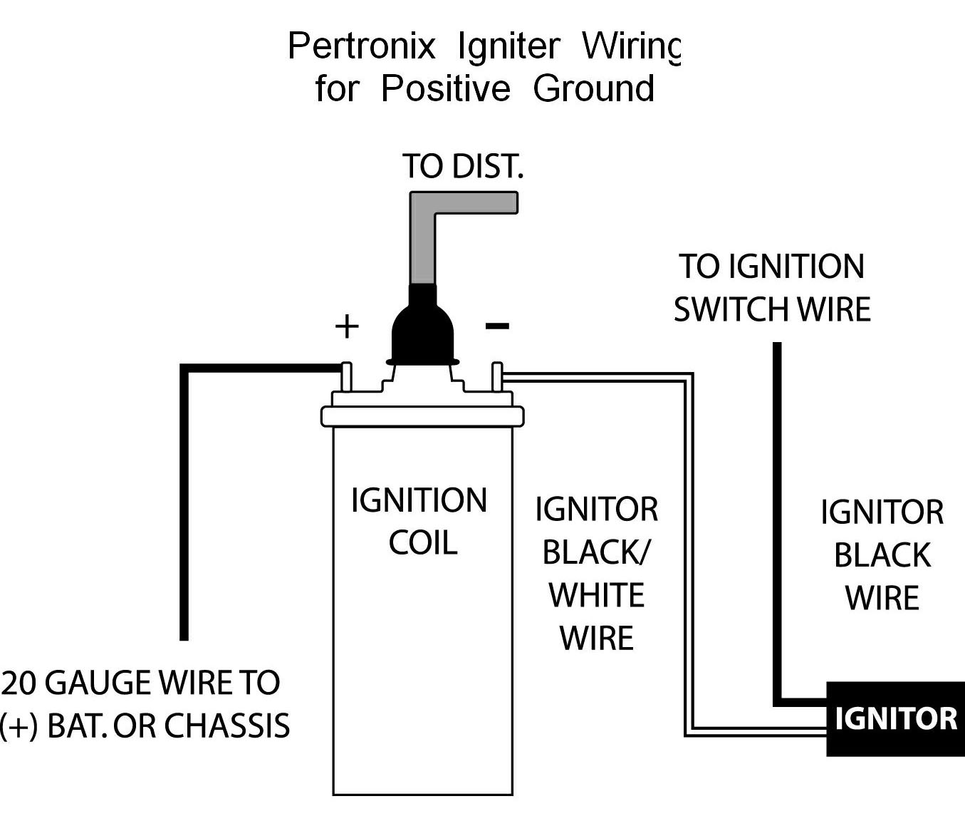
Pertronix Positive Ground Wiring
ricksfreeautorepairadvice.com › 2004-chevrolet2004 Chevrolet Silverado Fuse Diagram — Ricks Free Auto ... Mar 31, 2020 · 2004 Chevrolet Silverado Fuse Diagram for Underhood fuse box. STUD # 1 40A Trailer Wiring, Automatic Level Control (ALC) Compressor Relay MBEC 1 50A SEAT CB. RT DOOR CB BLOWER 40A Blower Motor LBEC 2 50A LOCKS Fuse. DDM Fuse, PDM Fuse, ECC Fuse, AUX PWR 2 Fuse STUD #2 30A Trailer Wiring ABS 60A Electronic Brake Control Module (EBCM)
Tech Wiki - Coil Wiring : Datsun 1200 Club
How to Connect a Ballast Resistor - DoItYourself.com Step 4: Install Ballast Resistor. Set the ballast resistor up to the firewall and screw the clamps in place. Step 5: Connect Wires to Positive. Strip the end of the positive wire from the ignition, and connect it to the positive end of the resistor. From the other terminal on the resistor a wire goes to the positive on the coil.

wiring ballast resistor - Studebaker Drivers Club Forum
PDF run through a ballast resistor or wire. Bypass any run through a ballast resistor or wire. Bypass any resistance unit to provide full 12V key ON power to the coil and module. If you set up a battery on a bench and hook up all the wires as shown you can check the spark by toggling the point lead (#5) to ground. You will see a nice hot spark out of the secondary. The circuit is quite simple and works
Old Britts, 12 V Dyna Coils & Mounting Kit
documents.holley.com › mallory_instructionsMallory Unilite Distributor Installation Instructions - Holley FIGURE 1 UNILITE® WIRING DIAGRAM USING BALLAST RESISTOR NOTE: The purpose of an ignition ballast resistor between the ignition switch (12V) and the ignition coil positive terminal is to restrict current flow through the ignition coil. Failure to use an ignition ballast resistor will eventually destroy the Ignition Module.

Ignition Coil Distributor Wiring Diagram - Wiring Forums ...
Fuel Pump ballast resistor wiring schematics? 88 cherokee ... Update: sadly I think the diagrams are incorrect. They do not show the correct circuit for the fuel pump power. the power for the fuel pump (not the fuel pump relay) goes through the ballast resistor. The resistor is not shown in the wiring diagram and neither is the electronics that bypass the resistor.

12V Ballast Ignition Solenoid
Ballast Resistor Wiring Diagram Points - easywiring A resistor wire or ballast resistor may or may not be included in the original equipment. The typical automotive ignition system prior to 1974 consisted of a coil and ballast resistor with breaker points to interrupt the current flow when a spark was needed. Diagram Wiring Diagram Ballast Resistor Ignition Coil Full Version Hd Quality …
Australian RR Forums: Car won't start
averagejoerestoration.com › 1965-mustang-wiring-diagrams1965 Mustang Wiring Diagrams - Average Joe Restoration Mar 10, 2014 · Where is the ballast resistor located for the ignition system in a 65 mustang, 289 2 barrel. This car is burning up points fast. Tom — July 8, 2013 9:46 PM . My brake lights have stopped working along with my turn signals. I am looking for the part that actually holds the light bulb in place in the rear. (Forgive me I do not know what they ...
Ballast Resistor Not Resisting? - Electrical - The Classic ...
Ballast Resistor Wiring Diagram Points - Wiring Diagram Ballast resistor wiring diagram points. Resistors wiring diagrams duration. According to the wiring diagram i have it goes to the ignition switch. In simple terms the ballast resistor in a mopar limits the amperage or current flow through the coil while the engine is running thereby extending the life of the coil and breaker points of.

How the ballast resistor coil work
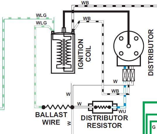
Wiriing around distributor, ignition coil & ballast resi ... Hi - can anyone explain, or does anyone have a simplified diagram showing how the wiring should run between the ignition coil, ballast resistor and the distributor. Someone previously has taken the ballast resistor out of circuit, and removed all the wiring, so not sure how it should be wired back in. This is for a Silver Shadow II.

Resistor wire & the persistent misfire
Ballast resistor and Duraspark II - Ford Mustang Forum ballast resistor. Connect the Red/Green wire to the output side of the ballast resistor. 5. Next connect the white wire to the "I" terminal on the starter solenoid. Note: If the solenoid being used do es not have an "I" terminal, the white wire must be connected to the "S" terminal of the solenoid. 6. The yellow wire is the signal for a tachometer.
Ignition Wiring | DodgeTalk Forum
1959 Ford F100 Ballast Resistor Wiring Diagram Pertronix wiring diagram in addition chevy ballast resistor wiring diagram together with 6 0 engine cooling diagram html furthermore mustang voltage regulator wiring diagram also 92 f engine diagram moreover toyota auris fuse box location moreover club car ignition wiring diagram in addition ford msd ignition wiring diagram together. Find great ...
Wiriing around distributor, ignition coil & ballast resi ...
Ballast Resistor Wiring Diagram Points - Wiring Sample Ballast Resistor Wiring Diagram Points. In a points type ignition the ballast resistor would help to keep the spark down and the coil from being burned up too quickly. Connect one side of the ballast resistor to the positive side of the coil. Diagram attached for wiring of points dizzy and coil with ballast resistor.

How the Ballast Resistor Works
How To Read A Ballast Wiring Diagram - Cadician's Blog Ignition Coil Ballast Resistor Wiring Diagram Another Blog About - How To Read A Ballast Wiring Diagram. Wiring Diagram will come with a number of easy to stick to Wiring Diagram Guidelines. It really is meant to help all the typical consumer in creating a correct method. These directions will be easy to understand and use.

Bypassing ballast resistor | For A Bodies Only Mopar Forum

ignition coil resistor - The 1947 - Present Chevrolet & GMC ...

66 Bel Air ballast resistor location? - Chevy Message Forum ...
Igniter and ballast wiring with painless | IH8MUD Forum
Compatible Ignition Coils, Ballast Resistors, Hot-Spark ...
123 ignition
Coil Confustication : MGB & GT Forum : MG Experience Forums ...
Ignition Ballast Resister - Melting? | Vintage Mustang Forums
62 ballast resistor purpose and readings? - CorvetteForum ...
MK2 Escort - Cranking and Firing, but dies straight away ...

240z Coil and Ballast Resistor Installation Help - ZDriver.com
How to bypass ballast resistor | ZCar Forum
Duraspark Resistor | The Ranger Station
No Tacho after accuspark and Ballast resistor : Electrical ...
12-VOLT NEGATIVE GROUND INSTRUCTIONS
Electronic ignition, Crane/Allison XR700
Resistor Wire Bypass - Ford Truck Enthusiasts Forums

Amplifier, Ballast Resistor and Coil - Early | Martin Robey
Ballast resistor wiring with electronic ignition?
Mopar electronic ignition wiring schematic question | For A ...
Bypassing ballast resistor | For A Bodies Only Mopar Forum
0 Response to "40 ballast resistor wiring diagram"
Post a Comment