37 3 wire coil diagram
Difference Between 2 wire RTD, 3 wire RTD, and 4 wire RTD's 3-wire construction is most commonly used in industrial applications where the third wire provides a method for removing the average lead wire 4-wire construction is used primarily in the laboratory where close accuracy is required. In a 4 wire RTD the actual resistance of the lead wires can be... 3 Wire Ignition Coil Diagram | autocardesign 3 Wire Ignition Coil Diagram Ignitionwiringjpg Wiring Schematic Diagram 3 Diddlhausen.
Diagramming motor/generator phase coil connections For each coil, the wire extending from the first turn was arbitrarily chosen to be the "positive" coil lead, and a small loop was twisted in its end in order The phase wiring used for the motor/generator being constructed here is as shown in diagram below. The details of why the connections are made as they...
3 wire coil diagram
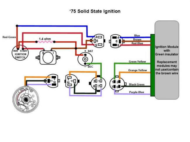
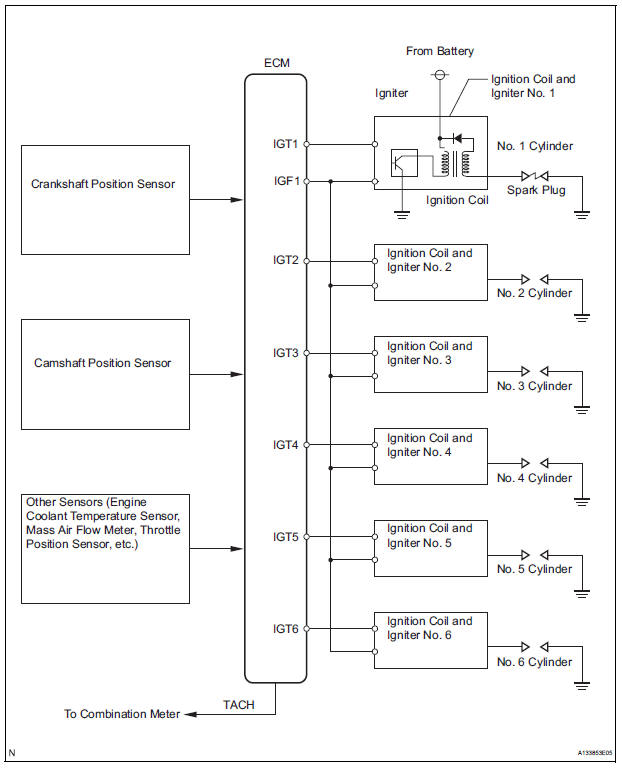
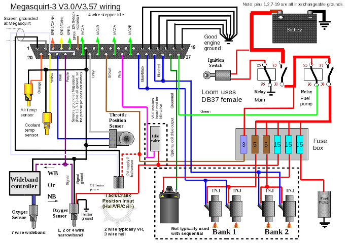
Wiring Diagrams A to Z for thee! « Myrons Mopeds Pacer Wiring Diagram for Dansi mag 101765 external ignition ground. Pacer Wiring: Pacer is an Italian moped with either a Morini MO1, MO2, or M1 engine. Early models with frame number 15499 and below, all have the Dansi 101286 3-wire 3-coil magneto, with the ignition source coil grounded... PDF Microsquirt Hardware Manual | 3: Wiring The following two diagrams illustrate good and bad wiring schemes showing where the troublesome voltage drops are created and how that would cause sensor These coils can directly accept the 0-5V logic level signal from the Microsquirt. The contain an ignition driver and a coil within the package. Part 3 -Testing and Troubleshooting 3 Wire COP Coils The Coil-On-Plug ignition coil to be tested is removed from its place and tester is attached to it. An assistant then cranks up the engine. The fastest way to identify the power and Ground circuits is using a wiring diagram. If you don't have one you'll have to find out by trial and error as you probe...
3 wire coil diagram. Wiring Diagrams Explained | How to Read Wiring Diagrams... A wiring diagram may include the wirings of a vehicle. For example, how the horns are powered and connected to the controller on your steering wheel. Below the coil, you see the 13-14 contact (NO Contact) of page two and also the other NO and NC contacts of this relay with the addresses they... WIRING DIAGRAMS AND TECH NOTES | Manualzz The diagram below shows the correct wiring. NOTE: If the PN 8910 Adapter does not fix the no-run situation, MSD offers a few "special Coil Wire Routing In some applications, the coil is mounted in the passenger compartment of the car. In this case, the coil wire must be routed through the firewall. Wiring and Sensors External Wiring Schematic. (This wiring diagram is for those creating their own harness for a V2.2 main board. The coil or tach lead connections depend on each particular set-up, check your maintenance manual, or ask on the list if someone has a vehicle similar to yours (give the make... Coil Inductance Calculator 3. Enter the coil diameter (form diameter + wire diameter - see diagram). 4. Enter the coil length (distance from first to last winding - see diagram). 5. Click Calculate.
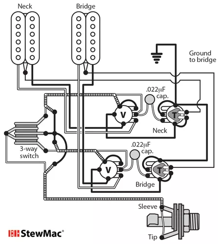
Hybrid coil - Wikipedia Wiring diagram of a single transformer hybrid. For use in 2-wire repeaters, the single transformer version suffices, since amplifiers in the The simple induction coil later evolved into a form of hybrid as a sidetone reduction measure, or volume of microphone output that was fed back to the earpiece. HSH + Coil Tap Wiring Diagram - Ultimate Guitar | Forum I've been doing a little bit of googling around to find wiring diagrams for the config I want to get going on my suhr modern satin. It's an HSH configuration and I'd like to get a new push-pull tone pot so I can access single coil sounds on positions one and five. Triple Maintenance Manual | H2 Wiring The alternator has three charging coils wound on laminations around the stator and wired together in a "wye." Each coil is joined on one end to a center (or neutral) connection. The other end of each coil is connected to a yellow wire. All three yellow wires go to the rectifier. Three Phase Electrical Wiring Installation in Home - NEC & IEC Schematic Wiring Diagram of Three Phase Distribution Board. Fig - Three Phase Distribution Wiring According to IEC Color Code. Note: The same description and details can be used for both NEC and IEC wiring diagrams as mentioned for the above general fig 1.
Wiring Diagrams - Lace Music Products All wiring diagrams for our pickups and some various diagrams for custom wiring. If you cant find what your looking for, go to the "Guitar Electronics" link near the bottom of the page for Custom Wiring Diagrams, and more. All pickup dimensions are located on each product page. How To Wire A Dual Voice Coil Speaker + Subwoofer Wiring Diagrams Voice coil wire leads & connection terminals. Single voice coil subwoofers have only one speaker voice coil winding while dual voice coil models have a 2nd voice coil of the same Ohm rating 4 Ohm dual voice coil sub wiring diagram. Click here to download the .PDF version you can view or print. Guitar Wiring Site Wiring the coils in parallel will produce a brighter tone (with somewhat less volume than series), but will still be humbucking. Again, the humbucker could be permanently wired in the manner shown in the above diagram. However, if you permanently wire the humbucker for series or parallel, you are... Wiring Diagrams for 2-way Switches, 3-way Switches, 4-way Switches... The 3 prong dryer wiring diagram here shows the proper connections for both ends of the circuit. This circuit originates from the breaker box containing a When the relay coil is energized, the contacts change state. The N.O. (normally open) contacts become closed and the N.C. (normally closed)...
Alternator wiring 3 wires - Ford Truck Enthusiasts Forums
PDF Wiring Diagram Book 4. Terminology. WIRING DIAGRAM A wiring diagram shows, as closely as possible, the actual location of all component parts of the device. Low voltage protection is a 3-wire control scheme using momentary contact push buttons or similar pilot devices to energize the starter coil.
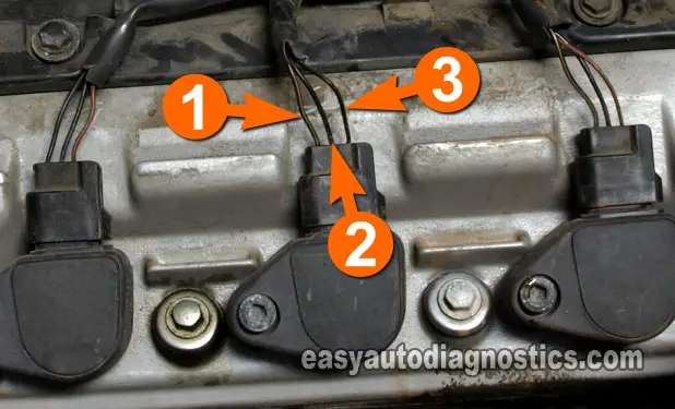
Part 1 -Testing and Troubleshooting 3 Wire COP Coils
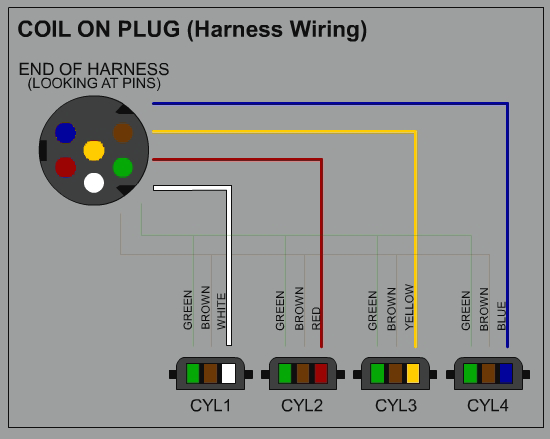
DIY Coil on plug conversion w/ electrical diagram | Forum 4. hook up the coil trigger wires between the wire harness a & b. as you can see in the wiring diagram coil #1 is white, #2 is red, #3 is yellow, #4 is blue. 5. crank the car over & test it out.
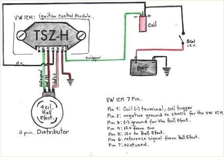
Mk3 CLI - Rev counter and oil light connected to TSZ-H - The ...
HSS Stratocaster Wiring Diagram with Coil Split Stratocaster Wiring Diagrams, Telecaster Wiring Diagrams, Les Paul - we have easy-to-follow Wiring Diagrams for Guitar and Bass! Telecaster wiring diagram with Humbucker neck and Single Coil bridge. 500K Resistor for a compensated tone.
Wires to ignition coil zetec | Focus Fanatics Forum
WIRING THE COILS IN 3 PHASES AXIAL FLUX... - Instructables THIS IS THE COMPLETE WIRING OF THE COILS and the hard part to understand. Pay close attention to this and look at the DIAGRAMS. There are some other diagrams I am working on that will be posted later. This is a Link to a Video that was made by my friend Muddy in YouTube about...
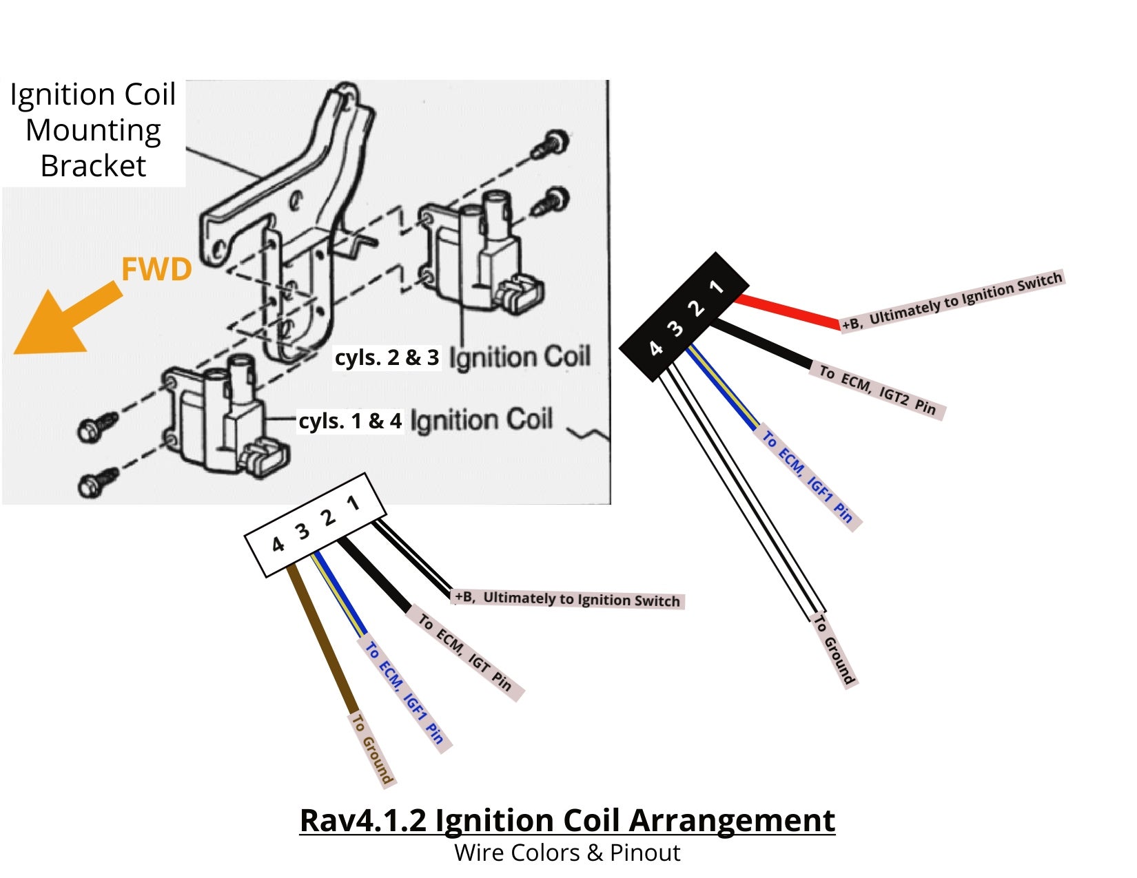
Ignition coil pinout help | Toyota RAV4 Forums
How Electromagnetic Coils Work - Circuit Basics | What is Magnet Wire? Learn how wire coils induce electromagnetic fields, how to generate current with a wire coil and a magnet, and how to A wire coil is an electrical conductor with one or more turns designed to produce a magnetic field. Using the materials above and following the simple diagram, do the following
Toyota Sienna Service Manual: Ignition Coil "A" Primary ...
Guitar Wiring Diagrams | 3 Single Coil Pickups Easy to read wiring diagrams for Strat style guitars with 3 single coil pickups. Options for custom switching, series/parallel phase & more.
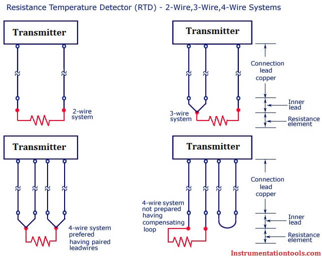
Difference Between 2 wire RTD, 3 wire RTD, and 4 wire RTD's
Wiring Diagrams | DiMarzio Tduo Wiring, DiMarzio Bridge Humbucker/IBZ Middle & Neck Single Coils, IBZ 5-Way Switch, 1 Push-Pull Volume (Split Bridge), 1 Tone; Neck, Neck & Middle, Middle, Middle & Bridge, Bridge.
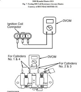
2000 Hyundai Elantra Loose Spark to Plugs: After the Motor Is ...
Three-Wire Control Circuit The three-wire control circuit is the most widely used motor control circuit. This circuit is similar to the two-wire circuit except In the ladder diagram notice that the stop push button is wired NC. When the start push button is depressed, voltage will flow through its contacts to energize the motor starter coil.
IronGear Pickups - Wiring
Induction Heater Circuit Using IGBT (Tested) - Homemade Circuit... A copper wire is considered more suitable to make the work coil as it can be connected easily and effectively to the water cooling. The following diagram suggest how a simple current limiting feature can be added to the above explained induction heater design.
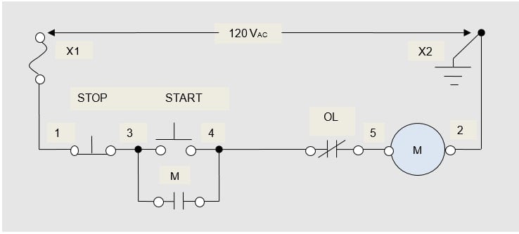
Understanding Three-Wire Control - Technical Articles
Alternator Wiring Diagram: A Complete Tutorial | EdrawMax This is a three-wire alternating wiring diagram showing the connections between the different components of a circuit. Whenever the voltage is below the desired value, the modules are triggered, and it changes the on-time of current flow through the coil.
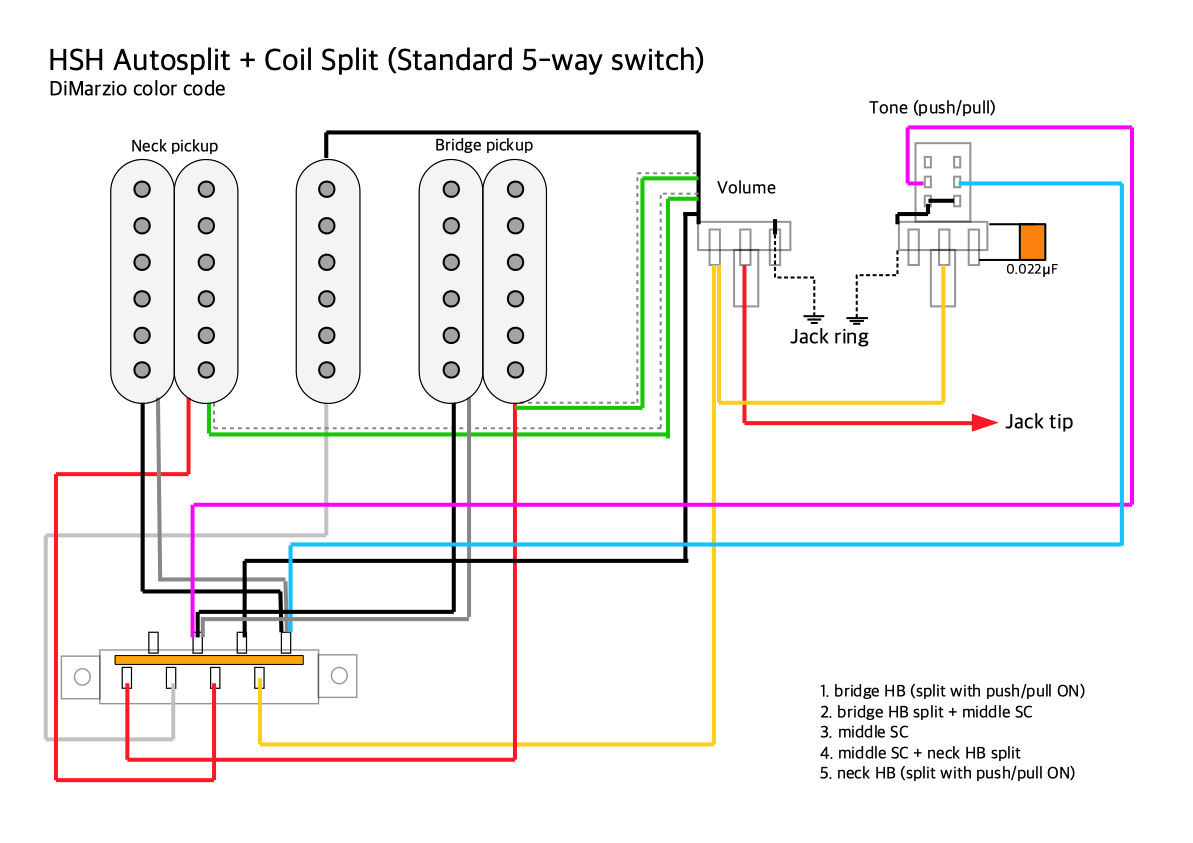
Pickups wiring: HSH autosplit with a standard 5-way switch ...
What is 3-phase electric Passing a magnet over a coil of wire causes lightweight negatively-charged electrons to come loose from their orbit around heavier positively-charged protons and begin jumping from atom to atom in a cascade of electrons moving down the wire. This is called electromagnetic induction.
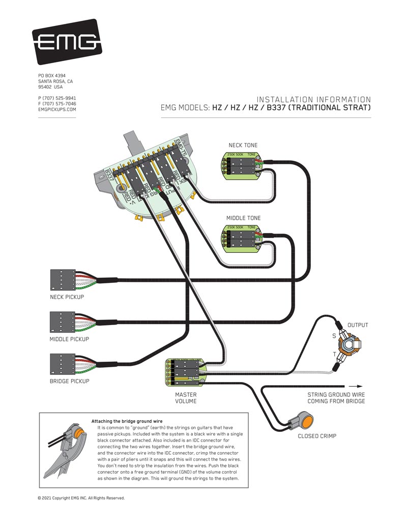
EMG Pickups / Top EMG Wiring Diagrams / Electric Guitar ...
Part 3 -Testing and Troubleshooting 3 Wire COP Coils The Coil-On-Plug ignition coil to be tested is removed from its place and tester is attached to it. An assistant then cranks up the engine. The fastest way to identify the power and Ground circuits is using a wiring diagram. If you don't have one you'll have to find out by trial and error as you probe...

Golden Age Humbucker - StewMac
PDF Microsquirt Hardware Manual | 3: Wiring The following two diagrams illustrate good and bad wiring schemes showing where the troublesome voltage drops are created and how that would cause sensor These coils can directly accept the 0-5V logic level signal from the Microsquirt. The contain an ignition driver and a coil within the package.
MSacc
Wiring Diagrams A to Z for thee! « Myrons Mopeds Pacer Wiring Diagram for Dansi mag 101765 external ignition ground. Pacer Wiring: Pacer is an Italian moped with either a Morini MO1, MO2, or M1 engine. Early models with frame number 15499 and below, all have the Dansi 101286 3-wire 3-coil magneto, with the ignition source coil grounded...

How-to-wire-3-phase-electric
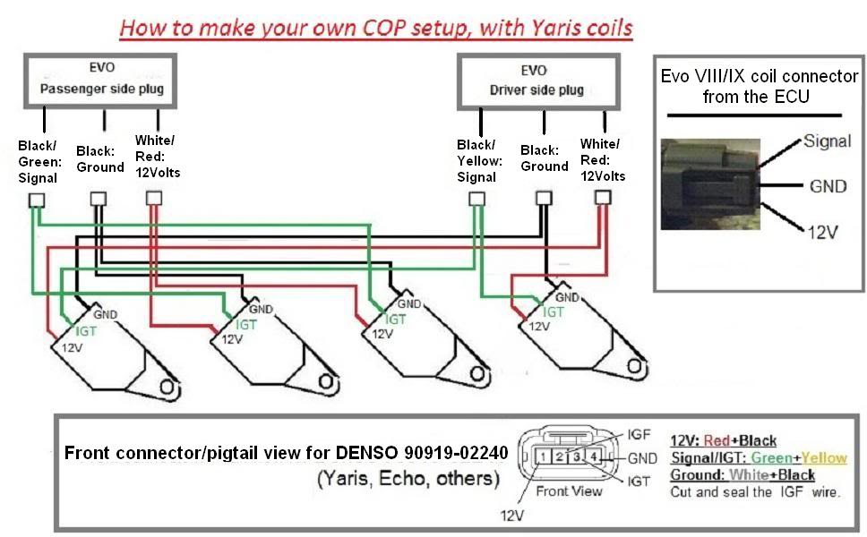
COP setup wiring (Denso 90919-02240, Yaris/Echo Schematics ...

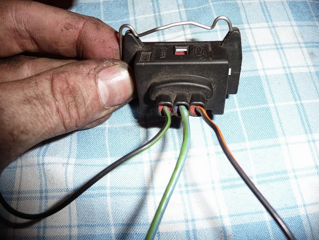
2 or 3 wire ignition coils-+ | Suzuki Forums

dRock96Marquis' COP Conversion Page
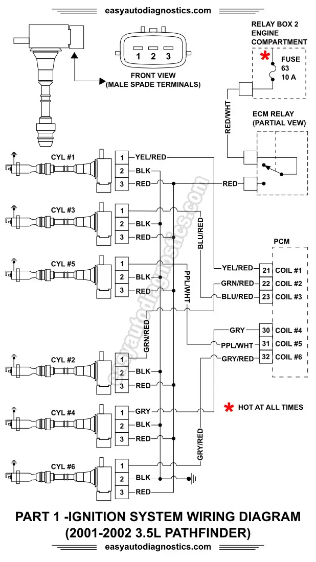
Part 1 -2001-2002 3.5L Nissan Pathfinder Ignition System ...
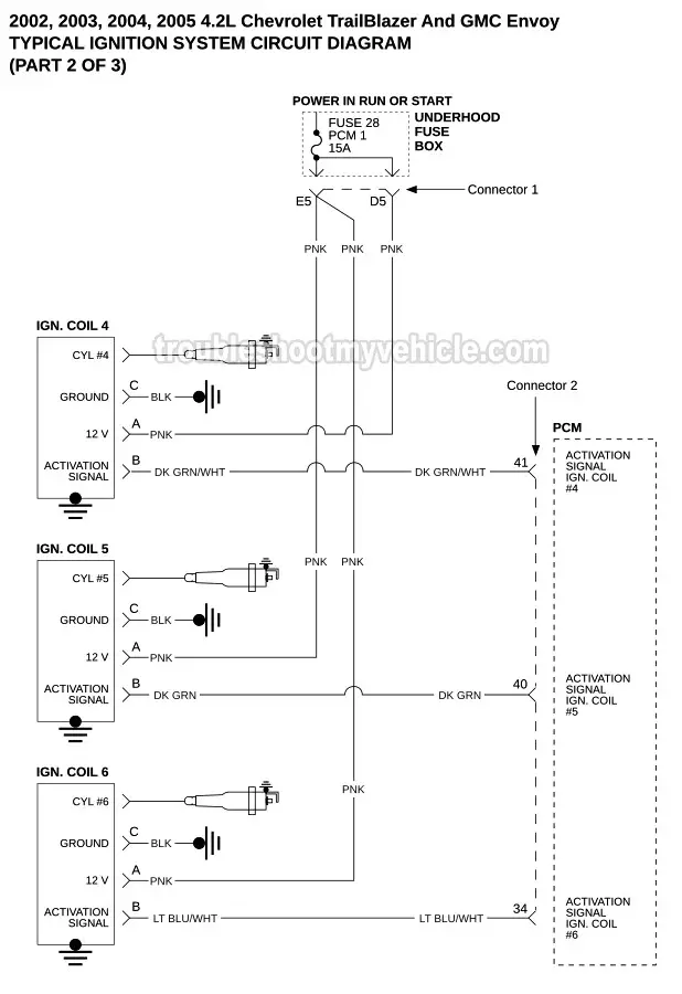
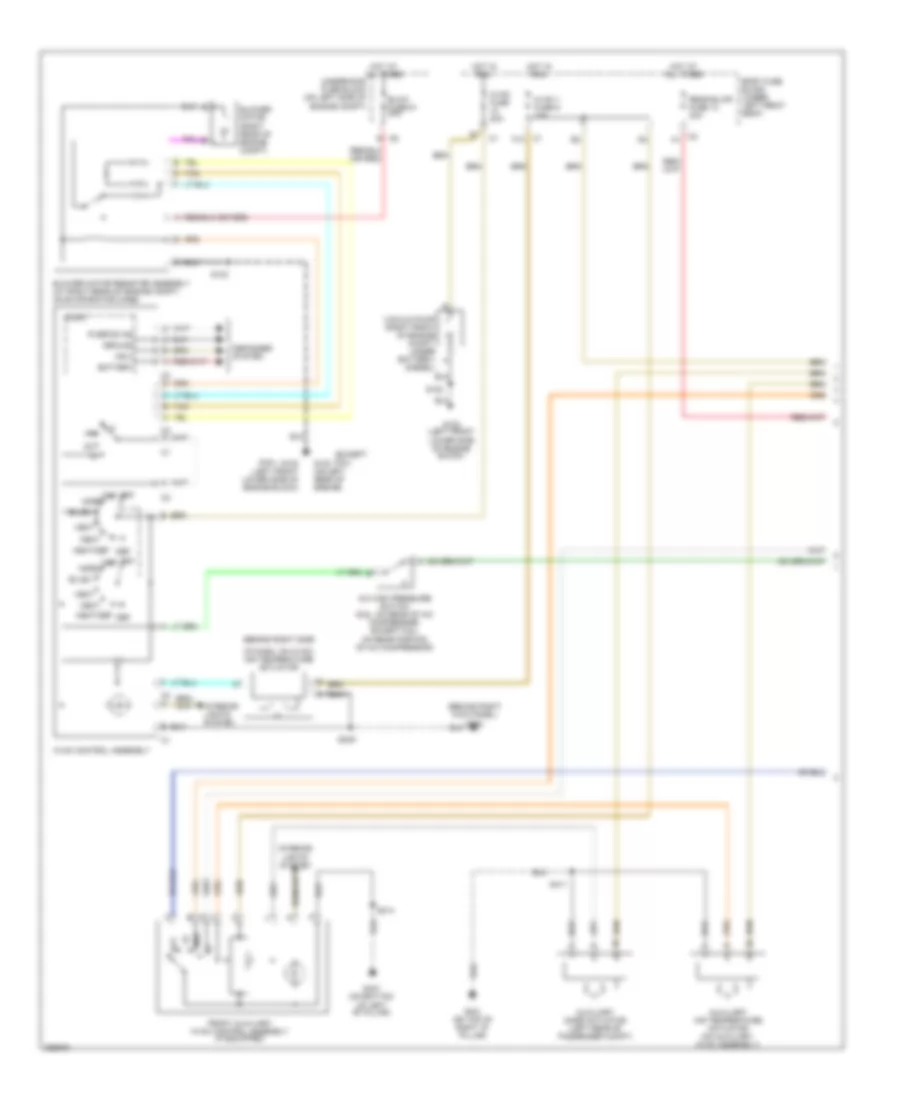
Ignition System Wiring Diagram (2002-2005 4.2L Chevrolet ...
Switchcraft 3-way Toggle Switch - StewMac

Three-Wire vs. Six-Wire Three-Phase Motors - Technical Articles

How to wiring DC solenoid valve with 3 wire - General ...

3-Wire Alternator Regulator Diagram - Seaboard Marine
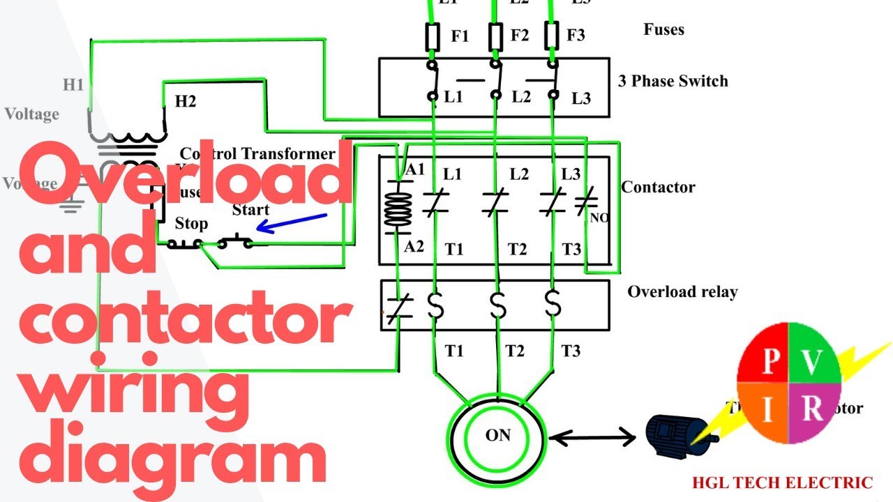
How to wire a contactor and overload. Start stop 3 phase motor control.

Quick/easy how-to: How to switch from igniter+3 wire coil to ...

Shut off coil with wire connect to relay. | Download ...
Coil On Plug Conversion - BMW Z3 DIYs

Mazda MX-5 COP/Coil-On-Plug Install – Motorsport Electronics

3 Wire Guitar Pickup Wiring Diagram | Guitar pickups, Guitar ...

PS GARAGE MOTORSPORT: COIL ON PLUG wiring for Mitsubishi ...

Series 2a & 3 IGNITION SWITCH WIRING - Series Forum - LR4x4 ...
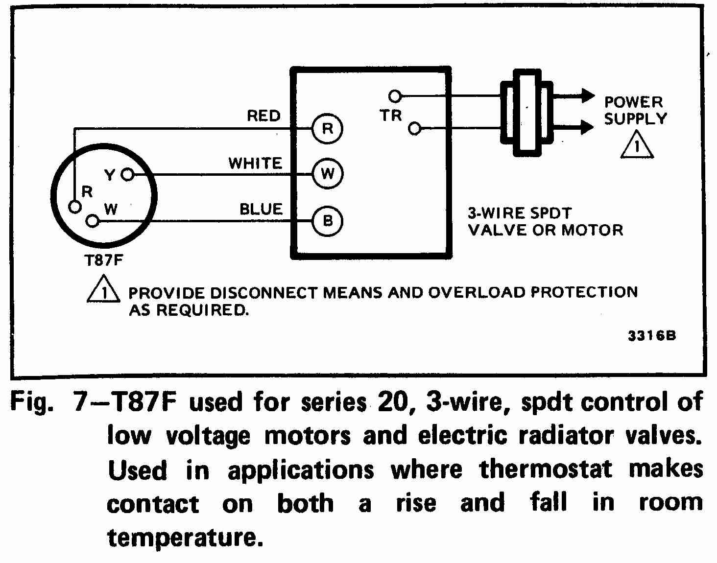
How Wire a Honeywell Room Thermostat Honeywell Thermostat ...
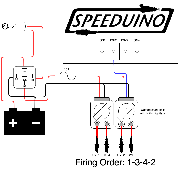
Ignition Wiring | Speeduino Manual
All Wiring Diagrams for Chevrolet Chevy Express G2007 2500 ...
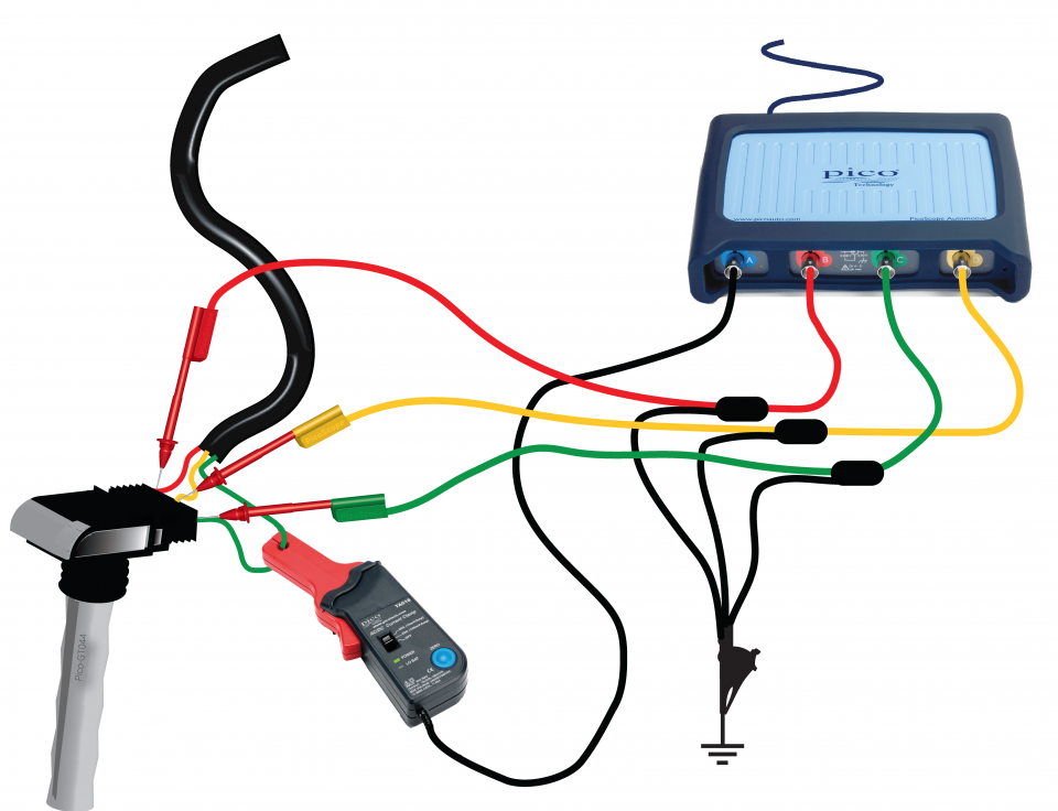
Coil-on-plug primary voltage and current (3-wire)
Wiring GM 3 wire - Idiot light not lighting | The H.A.M.B.
0 Response to "37 3 wire coil diagram"
Post a Comment