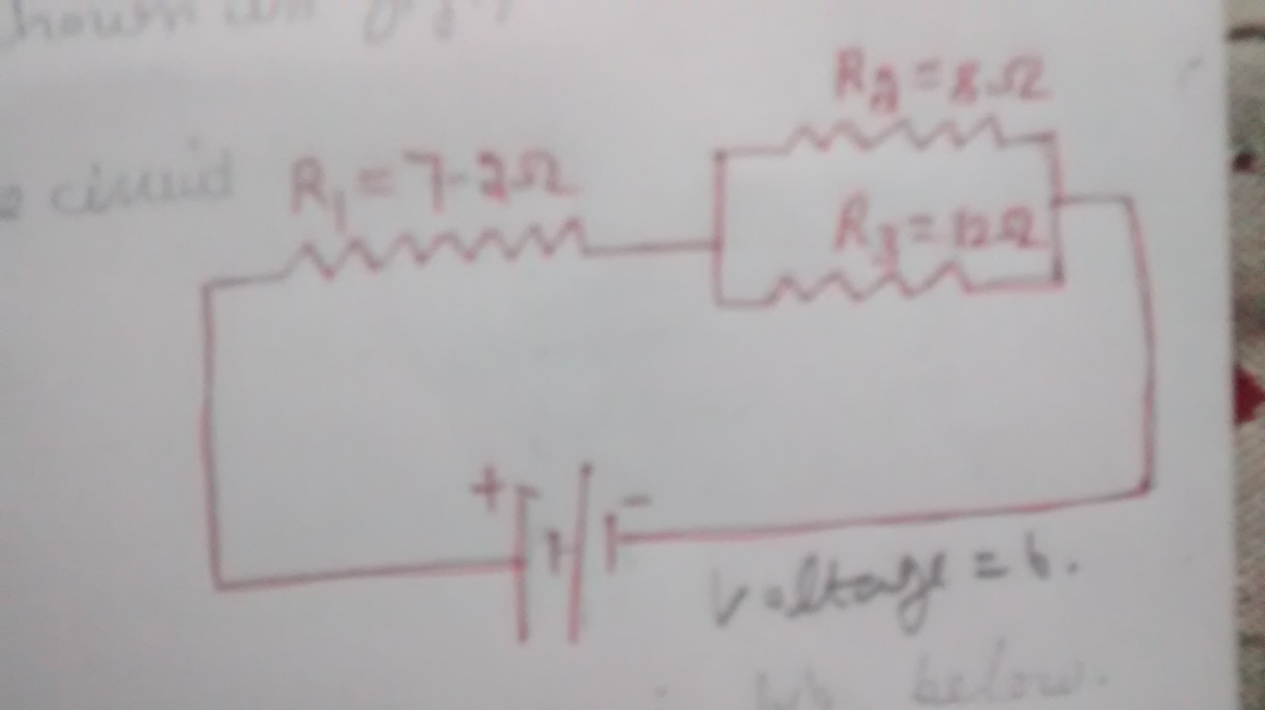
39 consider the circuit diagram depicted in the figure.
The conventional Nyquist diagram must be modified to apply the Nyquist stability criteria to the frequency-response plot. In a linear system, the crucial point on the Nyquist diagram is −1. For nonlinear systems the −[1/ N(ω, X)] locus corresponds to the critical point −1.To evaluate the stability of the system, both −[1/N(ω, X)] and the G(jω) function are plotted on the polar plane. Consider the circuit that is to detect the sequence “1001” on a serial bit-stream data input and produce a logic 1 output when the sequence has been detected, as shown in Figure 5.72.The state machine will have three inputs—one Data_In to be monitored for the sequence and two control inputs, Clock and Reset—and one output, Detected.
Sample Circuit We consider the ... Consider the circuit shown in Figure P28.9. Find (a) the current in the 20.0-Ω resistor and (b) the ... Draw the circuit diagram and assign labels and symbols to all known and unknown quantities. Assign directions to the currents.
Consider the circuit diagram depicted in the figure.
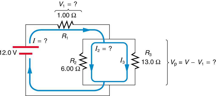
For example, consider a simple loop with no junctions, as in (Figure). ... Label points in the circuit diagram using lowercase letters a, b, c, … Court of Appeals for the 10th Circuit in a number of key areas. The quoted case descriptions are from Westlaw, except where described as quotations from Gorsuch.Planned Parenthood Ass’n of Utah v. Herbert, 839 F.3d 1301 (10th Cir. 2016) (dissented from denial of rehearing en banc) A 10th Circuit panel had ruled for Planned... What equation : 646641. Consider the circuit diagram depicted in the figure. What equation do you get when you apply the loop rule to the loop abcdefgha, in terms of the variables in the figure? 0 = If the current through the top branch is I_2 = 0.69 A, what is the current through the bottom, I_3, in amps?
Consider the circuit diagram depicted in the figure.. Physics Q&A Library Consider the circuit diagram depicted in the fgure. It is known that two battery internal resistors r1and r2 are both 0.2Ω· = 12V and & = 24V. R2 16Ω 2. and Rs 262, but Ri is unknown. Caution: Current directions. Problem: Consider the circuit in Figure 7.80a. Assume that the input C is driven by a square wave signal with a 50% duty cycle. Draw a timing diagram that ... But before I can bring you in the time machine to show you what I found, we need to get in our zoom machine—because as I learned the hard way, Elon’s wizard hat plans cannot be properly understood until your head’s in the right place. So wipe your brain clean of what it thinks it knows about itself and its future, put on... The Thevenin equivalent circuit is obtained after transforming the current source into a´ voltage source V(s) = Z(s)I(s) = RCv c(0) 1+sRC. This sequence of transformations is shown in Figure 3. Question 2 — Laplace domain circuit analysis Figure 4: RC circuit for Laplace analysis. Part (i) [3 marks] Consider the circuit depicted in Figure 4 ...
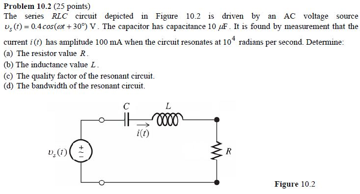
Consider this diagram. Let us assume that it describes a series circuit containing a resistor, a capacitor, and an inductor. The current in the circuit has amplitude , as indicated in the figure. Which of the following choices gives the correct respective labels of the voltages across the resistor, the capacitor, and the inductor? Question Consider the circuit diagram consisting of capacitors and a battery pictured on the board. Find the equivalent capacitance, the charge on each capacitor and the... Question Consider the circuit diagram depicted in the figure. What equation do you get when you apply the loop rule to the loop abcdefgha, in terms... Last week, software engineer Mario Fusco revealed on Twitter that in Italy , people had begun sharing a diagram of “the 5G chip that has been inserted in the [COVID-19] vaccine.” The diagram, seen below and labeled “confidential”—that’s how you know it’s legit—shows several elaborate circuits that apparently... We adopt the reversible FFT [] as an algorithm of the above Fourier transform and implement it as a quantum circuit whose computational complexity is. In this point of view, the processing speed is the same as the classical one, as long as we consider only a single data sequence. Nevertheless, there are following advantages...
Figure 12.2.2 (a) Time dependence of IR (t) and VR (t) across the resistor. (b) Phasor diagram for the resistive circuit. The behavior of IR (t)and can also be represented with a phasor diagram, as shown in Figure 12.2.2(b). A phasor is a rotating vector having the following properties: VR (t) (i) length: the length corresponds to the amplitude. Report of the Commission to Assess the Threat to the United States from Electromagnetic Pulse (EMP) Attack Critical National Infrastructures Report of the Commission to Assess the Threat to the United States from Electromagnetic Pulse (EMP) Attack Critical National Infrastructures Commission Members Dr. John S. Foster, Jr. Mr.... ... [Figure 1(b)]. The frequency-dependent chan-nel loss depicted in Figure 1(b) can be undone by means of a circuit having the inverse response, i.e., a high-pass filter (HPF). As illustrated in Figure 1(c), if subjected to such a response, the received data assumes its original, undispersed shape and more easily lends itself to detec-tion. As shown in the event tree logic diagram in Figure 31.4, ... being considered by the CEGB, especially where integrated generator circuit protection systems, ...
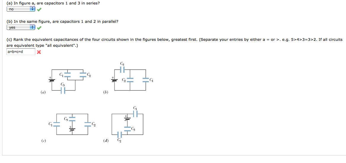
Solved: In Figure A, Are Capacitors 1 And 3 In Series? In ...
flattens the image histogram. Finally, we’ll briefly discuss the circuit implementation of the histogram... as the “cumulative normalized image histogram”. Let’s look at a simple example. Consider a 3-bit image... The above discussion is valid for the example function depicted in Figure 4. Can we extend this result to...
Solved: Consider The Circuit Diagram Depicted In The Figur ...
Figure 12.2.2 (a) Time dependence of IR (t) and VR (t) across the resistor. (b) Phasor diagram for the resistive circuit. The behavior of IR (t)and can also be represented with a phasor diagram, as shown in Figure 12.2.2(b). A phasor is a rotating vector having the following properties: VR (t) (i) length: the length corresponds to the amplitude.
Consider The Circuit Diagram Depicted In The Figure - Free ...
How to draw electrical single line diagram in excel How to draw electrical single line diagram in excel. How to draw electrical single line diagram in excel ...
Consider The Circuit Diagram In The Figure - General Wiring Diagram
First we will consider the circuitry that amplifies and conditions the voltage to be measured (the “Amp” block in figure 1). The deflection of the oscilloscope beam is proportional to the input voltage (after ac or dc coupling). The amount of deflection …
A Cyberphysics Page
P 5.2-2 Consider the circuit of Figure P 5.2-2. Find i a by simplifying the circuit (using source transformations) to a single-loop circuit so that you need to write only one KVL equation to find i a. Figure P 5.2-2 . Solution: Finally, apply KVL: 16 10 3 4 0 2.19 A aa 3 a
27 Consider The Circuit Diagram Depicted In The Figure ...
Figure 12.2.2 (a) Time dependence of IR (t) and VR (t) across the resistor. (b) Phasor diagram for the resistive circuit. The behavior of IR (t)and can also be represented with a phasor diagram, as shown in Figure 12.2.2(b). A phasor is a rotating vector having the following properties: VR (t) (i) length: the length corresponds to the amplitude.
Consider The Circuit Diagram Depicted In The Figure - Free ...
Transcribed image text: Consider the circuit diagram depicted in the figure. What equation do you get when you apply the loop rule to the loop abcdefgha, in terms of the variables in the figure? If the current through the top branch is I_2 = 0.47 A, what is the current through the bottom.
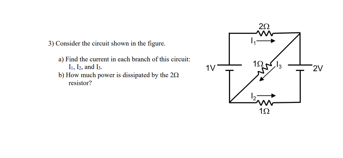
Answered: 3) Consider the circuit shown in the… | bartleby
Figure 3.1: Example of a circuit we can solve using nodal analysis ... In our circuit diagram we use the symbol shown below to indicate the ground node.
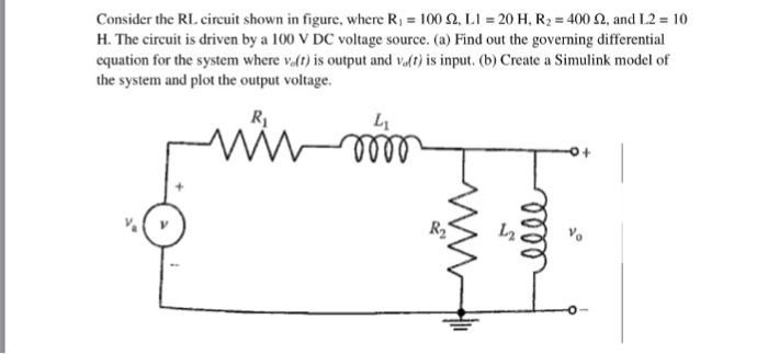
Solved: Consider The RL Circuit Shown In Figure, Where R_1 ...
The open-circuit voltage / short-circuit current approach can be used to calculate the Thevenin equivalent for a known circuit. Consider the circuit from ...

(Solved) Part Consider Circuit Figure 1 4 Bit Synchronous ...
Figure 6.13. State-assigned table for the sequential circuit in Figure 6.12. Present Next state state Outputs A 00 00 0 1 0 0 0 0 0 0 0 B 01 10 1 0 0 0 1 0 0 1 0 C 10 11 1 1 1 0 0 1 0 0 0 D 11 00 0 0 0 1 0 0 1 0 1
21.1 Resistors in Series and Parallel - BCIT Physics 0312 ...
21 to find an expression for vo in terms of VA,vb, and the resistance values. RA w. [. P14.21* The circuit diagram is:.

Mr Toogood Physics - EMF and internal resistance
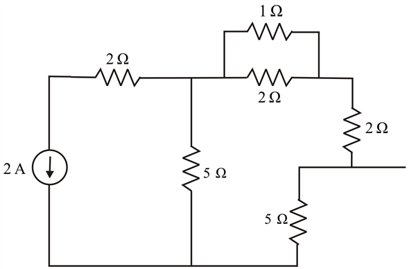
Nov 01, 2016 · The resulting circuit is shown in Figure 4. The circuit in Figure 4 has two current sources pointing in the same direction, and hence these can be replaced by a single current source whose value is equal to their sum, i.e., $$\frac{8}{3}\ A$$. Figure 4 . There are three resistors: two 5 Ω resistors and one 15 Ω resistor, all in parallel.
Consider The Circuit Diagram Depicted In The Figure ...
Transcribed image text: Consider the circuit diagram depicted in the figure. What equation do you get when you apply the loop rule to the loop abcdefgha?
Circuit Diagrams - DIYODE Magazine
Consider the circuit shown in Figure (a). i L(0-) = 0, and v R(0-) = 0. But, -v R(0-) + v C(0-) + 10 = 0, or v C(0-) = -10V. (a) At t = 0+, since the inductor current and capacitor voltage cannot change abruptly, the ...
31 Consider The Circuit Diagram Depicted In The Figure ...
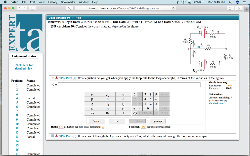
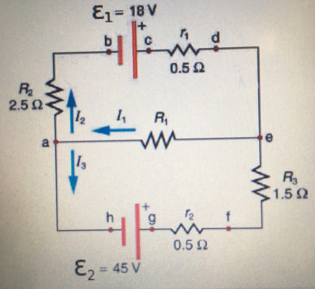
Answer to Solved (10%) Problem 10: Consider the circuit diagram. Transcribed image text: (10%) Problem 10: Consider the circuit diagram depicted in the figure. E1 = 18 V 250 R 0.522 E2-45V 50% Part (a) What equation do you get when you apply the loop rule to the loop abcdefgha, in terms of the variables in the figure?
31 Consider The Circuit Diagram Depicted In The Figure ...
Problem Details. Consider the circuit diagram depicted in the figure. Part (a) What equation do you get when you apply the loop rule to the loop abcdefgha? Part (b) If the current through the top branch is I2 = 0.49 A, what is the current through the bottom I3, in amps? Learn this topic by watching Kirchhoff's Loop Rule Concept Videos.
In the given circuit diagram, calculate : (a) the value of ...
connection in the circuit called ground. Often (but not always!), one pole of the DC power supply, either positive or negative, is that ground reference point. A... Because a differential amplifier amplifies the difference in voltage between the two inputs, each input influences the output voltage in opposite ways. Consider the... for the closed loop response in our circuit? This will predict phase... The three Figures shown below are... ...

Using Kirchhoff 's rules, calculate the current (Ig ) that ...
Transcribed image text: (10%) Problem 5: Consider the circuit diagram depicted in the figure 0.5 Ω R2 2.5 Ω /2 R 1.5Ω 0.5 Ω 50% Part (a) what equation do you get when you apply the loop rule to the loop abcdergha, in terms of the variables in the figure? Grade= 100% Correct Answer Student Final Submission Feedback Correct! 012 R2+ 112 T3 R3 +32-62 0- 1-(Ti +R2) I2+(R3r2)13 2 Grade Summary ...
Solved: Consider the seven-element circuit depicted in Fig ...
Problem 1: Consider the circuit depicted in the attached figure. The voltage source is an AC source of frequency f = 55 Hz. R, Randomized Variables C, R1 = 103 Q R2 = 162 Q C1 = 6.5 µF C2 = 9.5 µF V C2 R2 L = 0.77 H Part (a) Given the above circuit, write an expression for the total impedance Z for the circuit as a complex number.

unknown
A) Consider the combination of capacitors shown in the diagram, where C 1 = 3.00 μF, C 2 = 11.0 μF, C 3 = 3.00 μF, and C 4 = 5.00 μF.. Find the equivalent capacitance C A of the network of capacitors. Express your answer in microfarads. B) Two capacitors of capacitance C 5 = 6.00 μF and C 6 = 3.00 μF are added to the network, as shown in the diagram. Find the equivalent capacitance C B ...
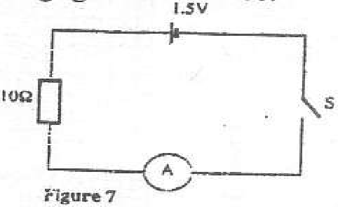
In the circuit diagram shown in figure 7, the ammeter has ...
Each electronic component in a given circuit will be depicted and in most cases its rating or other applicable component information will be provided. This type of drawing provides the level of information needed to ... Figure 3 is an example of an electronic schematic diagram. Figure 3 Example of an Electronic Schematic Diagram A second type ...

unknown
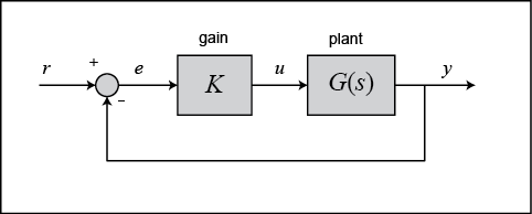
Exercise 2: Consider the feedback system depicted in the figure below a. Compute the closed- loop transfer function using the 'series' and 'feedback' functions b. Obtain the closed- loop system unit step response with the 'step' function and verify that final value of the output is 2/5. 52 Lab Experiment 5: Block Diagram Reduction ...
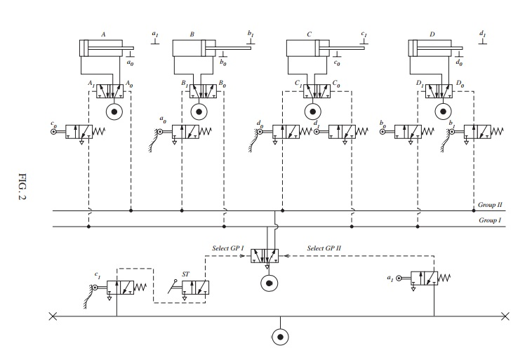
Solved: FIGURE 2 Shows A Pneumatic Circuit In Which Four A ...
[Q3] Consider the following state diagram for a synchronous circuit with one input X and one output Z. Analyze this state diagram and draw its circuit ...

Solved: Calculate The Three Currents I1,I2, And I3 Indicat ...
Suppose that these systems are connected in series as depicted in Figure P3.10. Find the input-output relation for the overall interconnected system. Is this sys tem linear? Is it time-invariant? x[n] System 1 - System 2 System 3 y[n] Figure P3.10 (d) Consider a second series interconnection of the form of Figure P3.10 where the
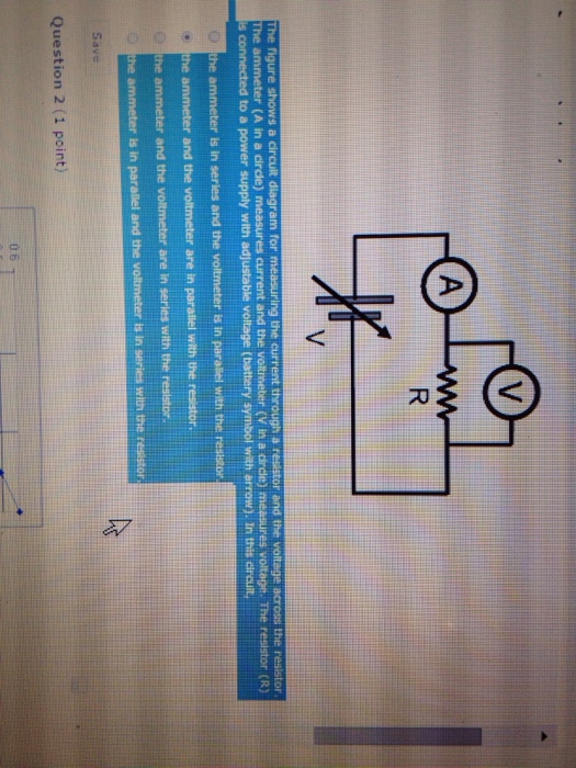
Solved: The Figure Shows A Circuit Diagram For Measuring T ...
In the proceedings below, the Federal Circuit held that the copied lines are copyrightable. After a jury then found for Google on fair use, the Federal Circuit reversed, concluding that Google’s copying was not a fair use as a matter of law. Prior to remand for a trial on damages, the Court agreed to review the Federal... ...
in the circuit diagram shown in figure calculate 1 total ...
In the following NOT transistor circuit diagram, the current flows through the 1K resistor and through the LED when the switch is open. This turns the LED on. When the switch is closed, however, the

A child has drawn electric circuit to study Ohm's law as ...
Similar logic suggests that attenuated viruses must have reduced or no replication in the CNS. Obviously, circuit-tracing strains of PRV replicate well in the nervous system. The first clue for understanding this apparent paradox is that the best tracing strain of PRV is not a wild type virus Wild type viruses are particularly...

In the circuit diagram given below: (a) Calculate the ...
for the Boss Metal Zone. The conspiracy theorists shared the schematic online, claiming it depicted the diagram... “Here in Italy people started to share this figure claiming that this is the diagram of the 5G chip that has been inserted in the COVID vaccine,” he tweeted. “In reality it is the electric circuit of a guitar...
31 Consider The Circuit Diagram Depicted In The Figure ...
Oct 25, 2019 · The diode is referred to as the rectifier in this circuit. During the period between t = 0 → T/2 of the AC waveform, the polarity of the voltage vi creates a "pressure" in the direction as depicted in the diagram below. This allows the diode to switch ON and conduct with a polarity as indicated just above the diode symbol.
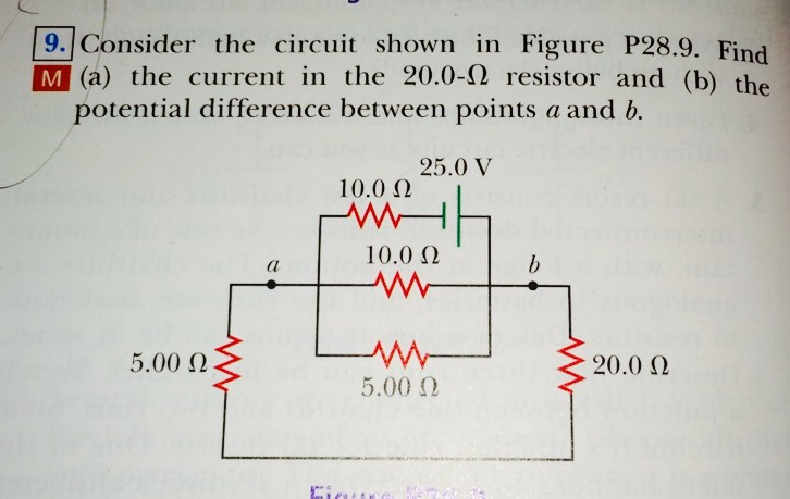
Solved: Consider The Circuit Shown In Figure P28.9. Find ...
REVIEW www.advquantumtech.com Exotic Quantum States of Circuit Quantum Electrodynamics in the Ultra-Strong Coupling Regime Mahn-Soo Choi The quantum coherent... 2020, 2000085 © 2020 Wiley-VCH GmbH2000085 (1 of 20) www.advancedsciencenews.com www.advquantumtech.com Figure 1. a) Schematic diagram of the circuit quantum... ...
In the circuit diagram shown below each resistance is of ...
Jul 13, 2019 · The circuit seen in the diagram above is a standard output current limiting protection circuit. Its operation is depicted in the diagram above: When the output current is too high, the voltage across RS (manganese copper wire) rises, and the voltage at pin 3 of U1 exceeds the reference voltage at pin 2.
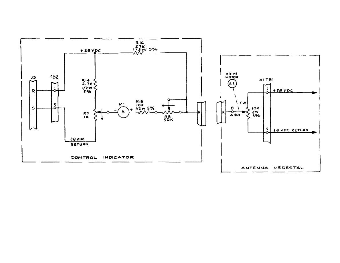
Figure 1-5. Cable Wrap Circuit, Simplified Schematic Diagram.
Consider the circuit diagram depicted in the figure. a. What equation do you get when you apply the loop rule to the abcdefgha, in terms of the variables in the figure?

people walking on road during daytime
20-1495 IN THE UNITED STATES COURT OF APPEALS FOR THE FOURTH CIRCUIT LEADERS OF A BEAUTIFUL STRUGGLE, et al., Plaintiffs–Appellants, v. BALTIMORE POLICE DEPARTMENT, et al., Defendants–Appellees. _______________________ On Appeal from the United States District Court for the District of Maryland at Baltimore... ...
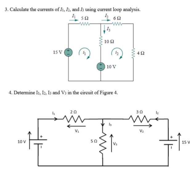
Solved: Calculate The Currents Of I1,I2 And I3s Using Curr ...
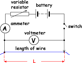
Set up the circuit according to circuit diagram 1), starting with just one cell. ... Examine the graph you made from the second table.
Consider The Circuit Diagram In The Figure - General ...
In the following circuit, consider the loop abc. The direction of the current through each resistor is indicated by black arrows. "going with current is drop, against current is gain" "The voltage gains when the current is flowing with the voltage" "drops 2 times at the split then gains when merging"
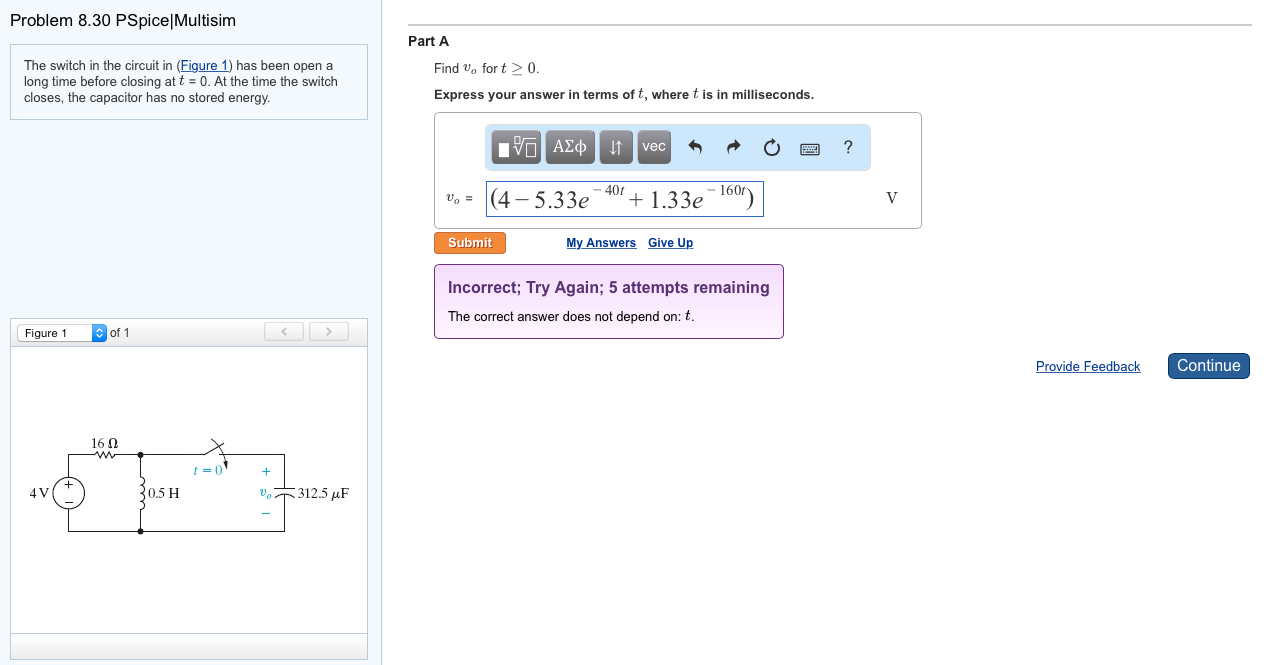
Solved: The Switch In The Circuit In (Figure 1) Has Been O ...
For more details on this and five other conjunctions of Mars involving other planets, see the planetary conjunctions section The star map applies to observers in the Northern hemisphere (i.e. North is up); for the Southern hemisphere view, click . The faintest stars shown on the map have an of about +4.8. Printer-friendly...

Consider The Circuit Diagram Depicted In The Figure ...
Experiment with an electronics kit! Build circuits with batteries, resistors, ideal and non-Ohmic light bulbs, fuses, and switches. Determine if everyday objects are conductors or insulators, and take measurements with an ammeter and voltmeter. View the circuit as a schematic diagram, or switch to a lifelike view.
Solved: The Lightbulb In The Circuit Diagram Of The Figure ...
Reviewer #1 (Recommendations for the authors):

flock of birds flying under white clouds during daytime
Note that all variables may not be required. α, β, θ, a, d, g, h, I 1, I 2, j, k, m, P, S, t Problem 2: Consider the circuit diagram depicted in the figure. Part (a) What equation do you get when you apply the loop rule to the loop abcdefgha, in terms of the variables in the figure?
0 Response to "39 consider the circuit diagram depicted in the figure."
Post a Comment