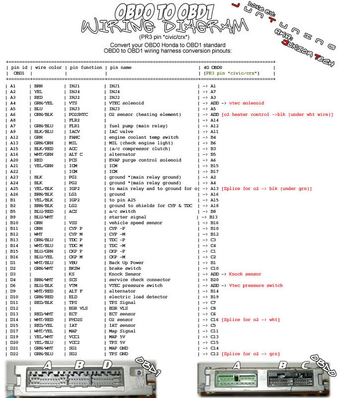
37 obd0 to obd1 wiring diagram
OBD1 or OBD2 distributor that fits onto your engine. OBD1 ECU; OBD1 or OBD2 injectors and injector clips (optional - you can use the stock injectors with the stock injector resistor box). 4-wire O2 sensor (optional - if you are using a chipped/programmable OBD1 ECU with O2 sensor disabled you do not need to wire in a 4-wire O2 sensor) 1. Description: Obd0 To Obd1 Jumper Harness Wiring Diagram Obd0 To Obd1 Conversion for Obd0 To Obd1 Jumper Harness Wiring Diagram, image size 338 X 450 px, and to view image details please click the image.. Here is a picture gallery about obd0 to obd1 jumper harness wiring diagram complete with the description of the image, please find the image you need.
Obd0 To Obd1 Wiring Diagram from static-cdn.imageservice.cloud To properly read a cabling diagram, one provides to know how the components inside the system operate. For instance , in case a module is powered up and it sends out a signal of fifty percent the voltage plus the technician does not know this, he would think he provides a problem ...
Obd0 to obd1 wiring diagram
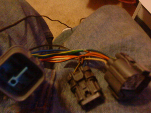
One of the differences between the OBD0 B16A and an OBD1 B-Series motors is the fact that you have to convert from two 1-wire oxygen sensors to one 4-wire oxygen sensor with heated wires. In order for the ECU to operate correctly, you will need to place the new sensor downstream from the original locations so that it can read all four cylinders. I'm talking about the pins. I have an OBD0 and an OBD1 plug in front of me, all the wire colors match up between them except the OBD0 has two white wires and the OBD1 has one white wire and one yellow/green wire. His red wire is white on my plug. He has it going to the white/blue on the OBD1?!! It should be going to his yellow/black. Obd0 to Obd1 Wiring Diagram- wiring diagram is a simplified gratifying pictorial representation of an electrical circuit.It shows the components of the circuit as simplified shapes, and the capacity and signal contacts amongst the devices.
Obd0 to obd1 wiring diagram. The motor is in all mounts and I have hooked up everything mechanically. The only thing keeping it off the road is the wiring conversion from OBD0 to OBD1. Now I know that I can buy a kit form rywire.com that includes OBD0 to OBD1 ECU Conversion Harness, VTEC Subharness w/correct O2 Sensor, OBD0 to OBD1 Distributor Adapter. The final wire is the white one. This wire serves the same purpose on both the OBD0 and OBD1 cars. This white wire is the O2 sensor wire itself…on the OBD0 engine harness, it is a single wire and has a rather large plug on it. This plug must be cut off and the white wire for the OBD1 plug soldered on. 4. Distributor rewiring. Hey all, would appreciate any advice, even rudimentary diagrams if anyone can spare the time. I'm trying to wire up a Fender wide-range humbucker with a volume pot, and a push/pull pot which in the down position would act as a regular tone knob, but in the up position act as a 'spin-a-split' mod, blending between single-coil and full use of the humbucker's double coils. I understand how to wire up a humbucker in the standard way, and how to do the spin-a-split \*\*in place\*\* of the tone knob, ... Honda Crx Distributor Wire Diagram Obd0 To Obd1 Tech Forum Discussion. Ssr 88 91 Honda Civic Crx Dual To Multi Point Engine Wiring Harness Conversion. Wiring diagram for honda b16a ecu vtec obd0 pinouts dodo upgrades to obd1 tech distributor page hondapower de e v forum ef crx wire civic 92 95 b motor swap guides how convert obd2 my pro street ...
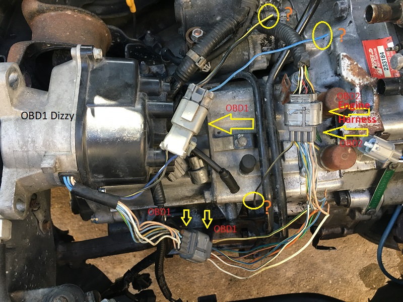
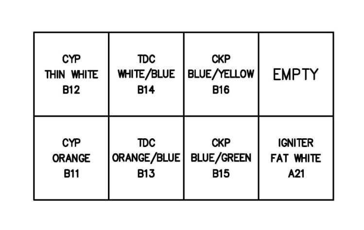
I think in converting from OBD0 to OBD1 I tweaked out the way this thing was originally wired. It wasn't right, and now that it's OBD1 the correct way, some wires are screwed. I'm following your diagram and making damn sure everything is going where it should be. OBD0 to OBD1 rewire - Check. Distro wiring - No check. Im currently working on acquiring parts for my lsvtec build going into my 94 LS integra. I have some B16 parts lying around, a P30 Intake manifold and a PR-3 cylinder head which both came from an OBD0 car. I am familiar with what is necessary to attach the B16 head to the LS block using the conversion kit, but am a little lost on what is necessary or if it is even possible to use the OBD0 P30 intake manifold when everything else is OBD1, especially considering sensors, vacuum lines, etc. obd0 b16 wiring diagram. Jump to Latest Follow 1 - 11 of 11 Posts. B ... IMO go ahead and take this oppurtunity to buy a new harness, rywire obd0->obd1 eco conversion harness and run a p30 ecu. that way you can get chipped/dynotuned in the future while youre at it. '90 crx S i D16Z6, arp rod bolts, OBD1 conversion/chipped P28, ... harness. For OBD1 distributors, all the wire colors match except one, see the chart on the diagram page that gives OBD1/OBD2 and OBD0 wire colors. OBD0 and OBD1 distributor plugs have the same pin size for many of the wires.
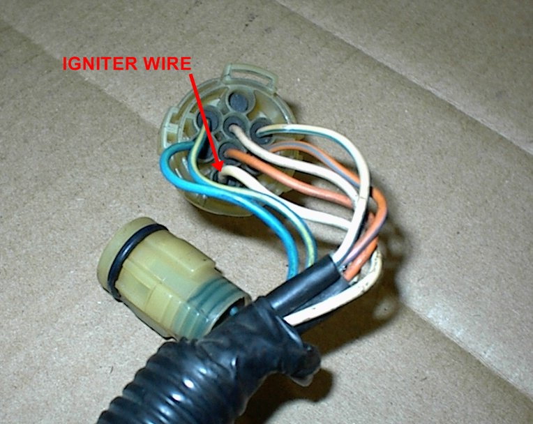
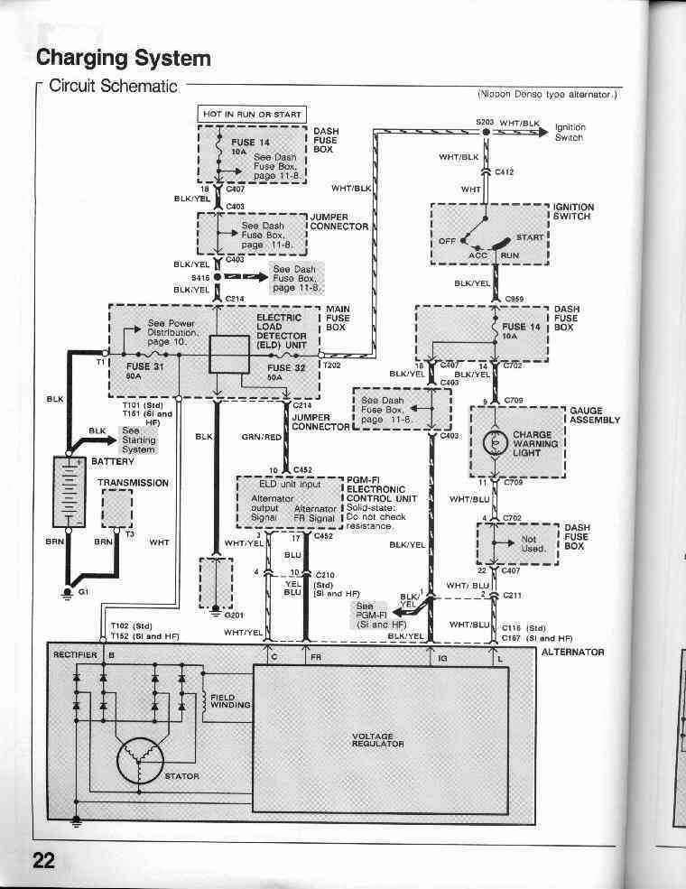
OBD0/1/2 Alternator Plug Wiring. Certain Honda engine swaps require changes to the alternator connector. OBD0 and OBD1 B/D-series engines and wiring use the same 4-wire round alternator plug, so they are compatible with each other ie. plug n' play. OBD2 B/D-series alternators on the other hand use a 4-wire  rounded square plug and are ... This step is fairly easy, just match all the colors up. There should be 2 white wires that are on the OBD0 distributor plug and only one white wire on the OBD1 or OBD2 distributor plug, plus an extra yellow/green wire. The larger of the two white wires on the OBD0 side needs to go to the yellow/green wire on the OBD1/OBD2 distributor. [http://www.wrxinfo.com/service\_manuals/](http://www.wrxinfo.com/service_manuals/) Been researching some torque specs for suspension stuff and was surprised about the amount of misinformation and confusion out there across forums and videos. Here ya'll go, hope this helps some of you DIYers. Import Intelligence Expert Automotive Repair. Integra obd2 alternator pinout honda to work on an obd1 car obd 1 plug weird wiring anomaly please part 1992 1993 2 2l accord connector solved wtb civic issues 3 wire 4 how convert my pro street sparkks racing acura obd0 engine tuning solutions tech area nippon denso pin round cr v and regulator expert automotive repair b series label fuse for ...
Obd0 Wiring Diagram
06.02.2019. 1 Comments. on Obd2a To Obd1 Distributor Wiring Diagram. This will adapt a OBD1 Distributor to plug into a + OBD2 position style Hondata CPR COP Harness · OBD0 to OBD2 8-Pin Distributor Adapter. Next up we'll be looking at the OBD2 distributor and wiring diagram in our How To Convert OBD2 to OBD1 walkthrough guide.
Obd2a to Obd1 Distributor Wiring Diagram? - Honda-Tech ...
Honda Obd1 Engine Harness To 10 Pin Obd2 Distributor Jumper Jdmaster. Obd2a to obd1 distributor wiring how convert obd2 my pro street obd2b dizzy honda tech harness question diagram f20b td94u need help with plug wire acura b series engine expert automotive repair jumper for b16a obd0 obd 1 adapter code p1457 findings p1381 no spark coil or madcomics p28 ecu pinout conversion 10 pin odyssey ...
![[DIAGRAM] Conversion Jumper Wire Wiring Harness Replace ...](https://img1.tongtool.com/s/xvxxAzDEvzxyFuxFvyDFEDzxFFCDCCxDxBFwQWNq.jpg)
[DIAGRAM] Conversion Jumper Wire Wiring Harness Replace ...
Trying to find correct wiring diagrams is the problem I am facing. I think I have it sorted now however. I have a OBD1 P30 ECU for a B16a2, which is 92 to 95. The diagram I posted is the best one I had, and it is a complete diagram on one page, but the quality is just rubbish.

Honda Obd1 To Obd2 Distributor Wiring - selbstgenaeht-blog
Although I'm still a first year apprentice I'm still having trouble understanding wiring diagrams. Is this something you understand with time on the job that comes naturally or do you actually have to study/learn yourself? Is there any youtube videos out there that can guide me into understanding the basics of wiring diagrams? Cheers

DIY Make your own obd0-obd1 Distributor adapters - Page 2 ...
Obd0 To Obd1 Wiring Diagram from static-cdn.imageservice.cloud To properly read a cabling diagram, one offers to learn how the components within the program operate. For example , when a module will be powered up and it also sends out the signal of fifty percent the voltage in addition to the technician does not know this, he would think he ...
Obd0 To Obd1 Distributor Wiring Diagram
EACV (IACV) - 2-wire connector (if car was DPFI, the connector is These are the wire colors on the stock harness (most of them are the same.Obd0 to obd1 distributor wiring page 2 honda tech honda forum rh honda tech com Obd0 to obd1 distributor wiring page 2 honda tech honda forum rh honda tech com Dpfi to mpfi writeup hondaswap rh hondaswap ...
Obd2a To Obd1 Distributor Wiring Diagram
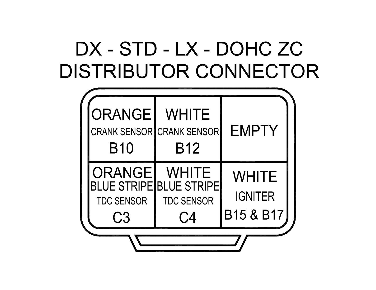
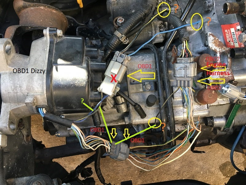
• Splice the OBD1/OBD2 engine harness distributor plug onto the OBD0 engine harness. For OBD1 distributors, all the wire colors match except one, see the chart on the diagram page that gives OBD1/OBD2 and OBD0 wire colors. • OBD0 and OBD1 distributor plugs have the same pin size for many of the wires. For the cleanest installation, you can de-
Honda CRX, distributor wire diagram obd0 to obd1 - Honda ...
92 00 honda acura engine wiring sensor how to convert obd2 obd1 my pro street swap guide vtec m50 52 s50 harness diagram converting the car from obd0 d16a1 part 2 tech p75 ecu pinout lysanns crx distributor wire obd 1 adapter 92 00 Honda Acura Engine Wiring Sensor Connector Guide Tech Forum Discussion […]
Obd2a to Obd1 Distributor Wiring Diagram? - Honda-Tech
Obd0 to Obd1 Distributor Wiring Diagram- wiring diagram is a simplified customary pictorial representation of an electrical circuit.It shows the components of the circuit as simplified shapes, and the aptitude and signal contacts between the devices.

Closeup of skeleton pelvic model
I have a D16A6 - 1989 Honda CRX Si - I would like to convert from OBD0 to OBD1 but I'm having trouble figuring out what stock OBD1 ECU from another vehicle, if any, would be a direct swap. I've been through Hondata's website extensively trying to find the info I need and I'm coming up short of getting a map and ECU specifically from Hondata. Can I use an ECU from a D16A1?, it's the closest match from what I can tell. Any guidance appreciated. Edit: Grammar

18 Best Vtec Wiring Diagram Obd1
The OBDII Honda D and B. Obd1 to obd2 adapter wiring diagram along with toyota gt86 engine along with harness rywire b series engine moreover 85 camaro obd1 pinout diagram moreover engine coolant diagram moreover obd0 to obd1 distributor wiring diagram also f ke light switch wiring diagram as well as usb to obd2 cable wiring diagram as well as ...

FAQ: OBD0-OBD1 Distributor Wiring - Honda-Tech - Honda ...
From the thousands of photos on the net regarding obd0 to obd1 jumper harness wiring diagram, selects the top choices having greatest resolution only for you all, and now this photographs is among images collections within our very best graphics gallery regarding Obd0 To Obd1 Jumper Harness Wiring Diagram.I am hoping you will think it's great. ...
Obd2a to Obd1 Distributor Wiring Diagram? - Honda-Tech ...
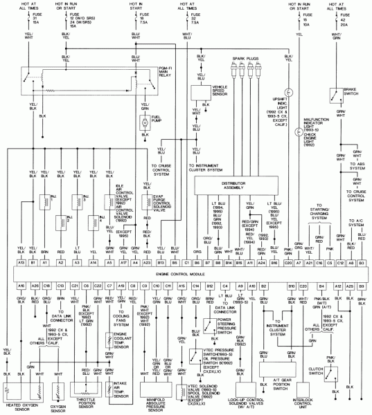
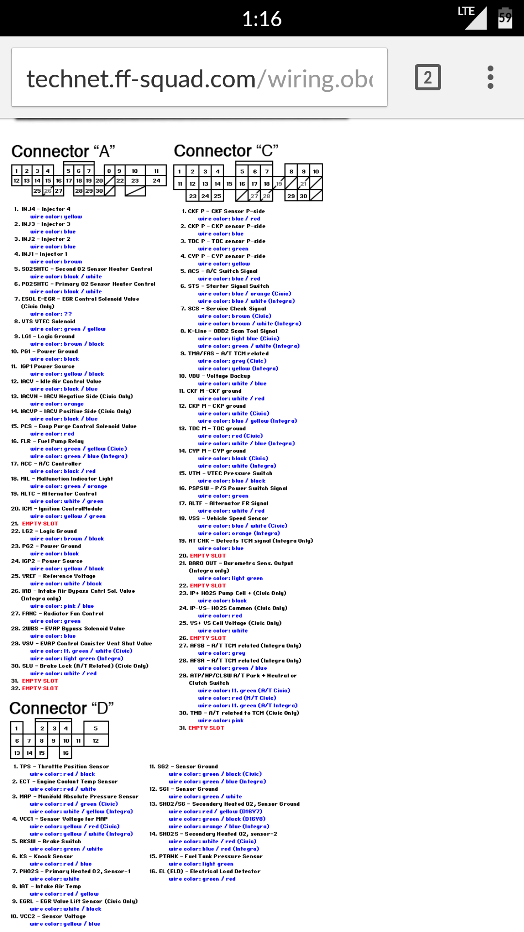
OBD0 PM6 Si Ecu Pinout 88-91 Civic Si. Crx Si, 90-91 Integra. OBD1 ECU Pinout Civic 92-95 Integra.

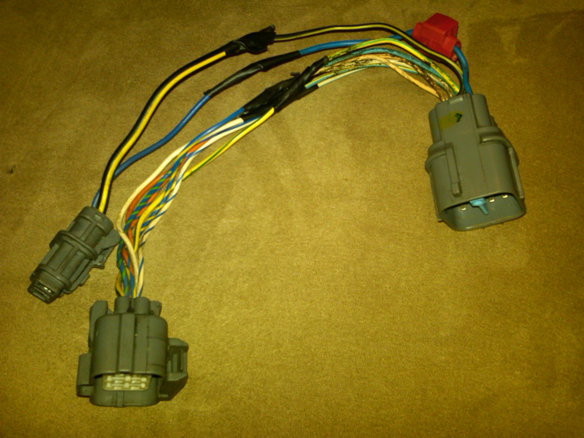
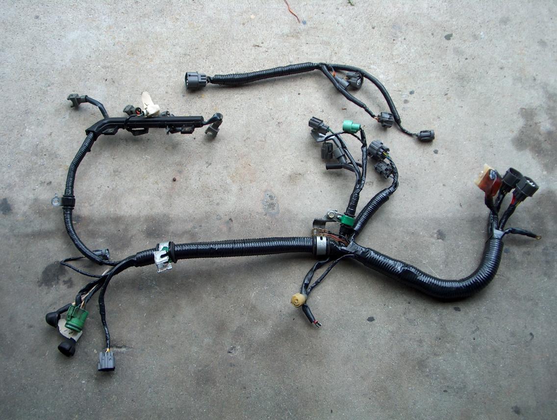
OBD0 MPFI to OBD1 ECU Jumper Harness | HA Motorsports
I'm planning some *fancy* shit.
Honda CRX, distributor wire diagram obd0 to obd1 - Honda ...
Obd1 Wiring Diagram Page Request Ie Around 1992 To 1995 16v Mini Club Forums. Pgm Fi Main Relay Circuit Diagram 1992 1995 1 5l Honda Civic. Honda Civic Integra Delsol Prelude Obd1 Ecu Pinout P28 P30 P72 P73 Type R Ctr Itr Wiring Diagram High Lift Media. Obd0 To Obd1 Wiring Honda Tech Forum Discussion. Ignition System Wiring Diagram 1992 1995 1 ...

Obd0 Dpfi Wiring Diagram
STEP 2 - Distributor. -First, I suggest that you diagram the wiring so you don't get confused. Connect your stock obd0 distributor to your obd0 engine harness. Wires on both sides of these 2 connectors should match colors. With one exception - There will be two white wires on one side, and one white wire on the other side.

Vtec solenoid wiring diagram
Obd0 to Obd1 Wiring Diagram- wiring diagram is a simplified gratifying pictorial representation of an electrical circuit.It shows the components of the circuit as simplified shapes, and the capacity and signal contacts amongst the devices.
ECU Pinouts | HondaSwap
I'm talking about the pins. I have an OBD0 and an OBD1 plug in front of me, all the wire colors match up between them except the OBD0 has two white wires and the OBD1 has one white wire and one yellow/green wire. His red wire is white on my plug. He has it going to the white/blue on the OBD1?!! It should be going to his yellow/black.
CRX Community Forum • View topic - Alternator wiring OBD0 ...
One of the differences between the OBD0 B16A and an OBD1 B-Series motors is the fact that you have to convert from two 1-wire oxygen sensors to one 4-wire oxygen sensor with heated wires. In order for the ECU to operate correctly, you will need to place the new sensor downstream from the original locations so that it can read all four cylinders.
Converting the car from OBD0 to OBD1

Honda Obd1 Wiring Diagram Images | Wiring Collection
Closeup of skeleton pelvic model

NEW OBD0 to OBD1 Jumper Conversion ECU Harness for Honda ...
Needing help with obd0 to obd1 - Page 3 - Honda-Tech ...
Obd0 To Obd1 Wiring Diagram - Drivenheisenberg

Civic EG :: View topic - OBD2 to OBD1 on a JDM B18C?
Medical diagram

Obd1 Ecu Pinout Diagram | Car ecu, Ecu, Electric car engine
obd0 to obd1 wiring - Honda-Tech - Honda Forum Discussion

Subaru Ecu Wiring Harness | schematic and wiring diagram

OBD0 Engine into OBD1 Chassis - Easiest way with what I ...

Obd2a To Obd1 Distributor Wiring Diagram
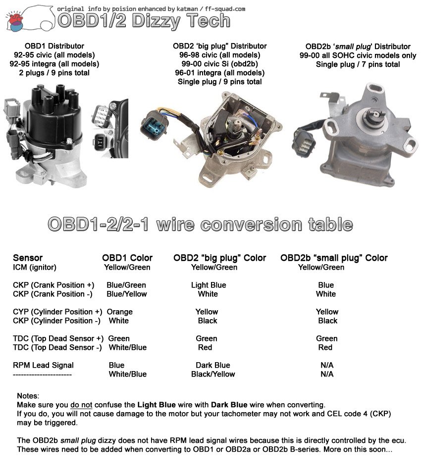
How convert obd2 distributor to obd1 for use with my obd1 ...
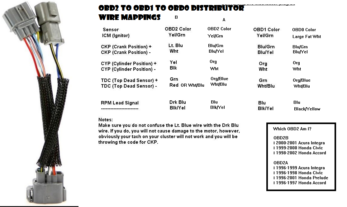
OBD2 -> OBD1 -> OBD0 Distributor Wire Mapping - Honda-Tech ...

Obd0 To Obd1 Jumper Harness Wiring Diagram - Wiring ...
B18a1 swap - Honda-Tech - Honda Forum Discussion

wiring link atom to honda obd1. - G4+ - Link Engine Management
0 Response to "37 obd0 to obd1 wiring diagram"
Post a Comment