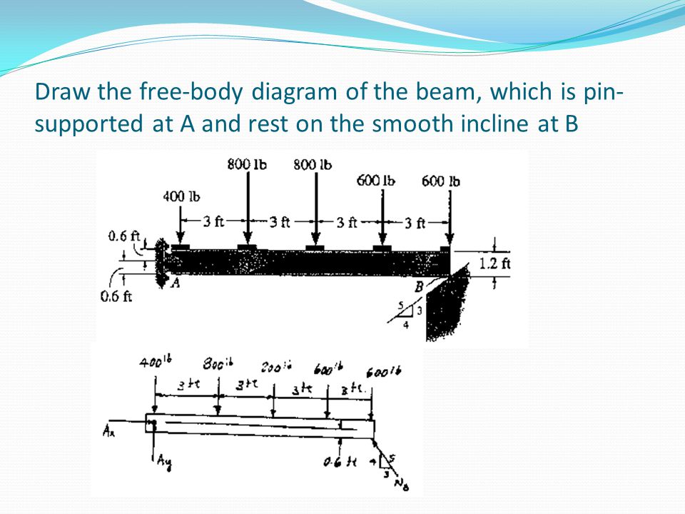
40 draw the free-body diagram for the beam. a is a rocker and b is a pin.
A short video to show how to form an imaginary cut and draw a free body diagram of a simply supported beam with a point load.Related videos:Reactions of a Si... Draw the free-body diagram for the beam. A is a rocker and B is a pin. Draw the vectors starting at the black dots. The location and orientation of the vectors will be graded. The length of the vectors will not be graded.
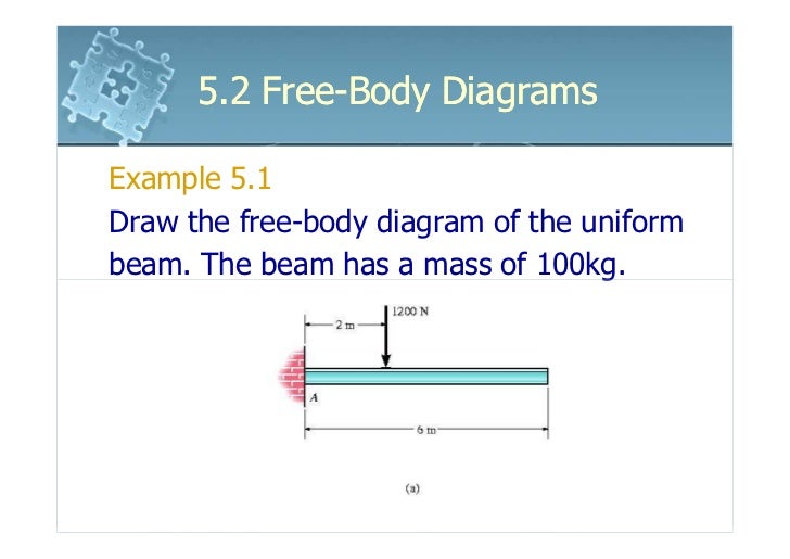
FREE-BODY DIAGRAMS (Section 5.2) 2. Show all the external forces and couple moments. These typically include: a) applied loads, b) support reactions, and, c) the weight of the body. Idealized model Free-body diagram (FBD) 1. Draw an outlined shape. Imagine the body to be isolated or cut "free" from its constraints and draw its outlined shape.
Draw the free-body diagram for the beam. a is a rocker and b is a pin.
The beam shown below is supported by a pin at A and roller at B. Calculate the reactions at both supports due to the loading. 20 kN 40 kN 2 m 3 m 4 m A B EXAMPLE 1 . Draw the free body diagram: By taking the moment at B, List the Knowns/Unknowns and Draw the Free-body diagram of the beam, which is pin connected at A and rocker-supported at B 500 N 800 . List the Knowns/Unknowns and Draw the Free-body diagram of the bar, which has a negligible thickness and smooth points of contact at A, B, and C. Engineering Mechanics - Statics Chapter 5 Problem 5-10 Draw the free-body diagram of the beam, which is pin-connected at A and rocker-supported at B. Given: F = 500 N M = 800 N⋅ m a = 8m b = 4m c = 5m Solution: Problem 5-11 The sphere of weight W rests between the smooth inclined planes. Determine the reaactions at the supports.
Draw the free-body diagram for the beam. a is a rocker and b is a pin.. Draw the free-body diagram of the dumpster Dof the truck, which has a weight of 5000 lb and a center of gravity at G. ... Draw the free-body diagram of the beam, which is pin connected at Aand rocker-supported at B. SOLUTION. B 5 m. A. 8 m 4 m. ... Determine the horizontal and vertical components of reaction at the pin Aand the reaction of the ... Let us first draw a free body diagram showing all the forces affecting the beam. Remember that since the beam is in equilibrium, all forces added must equal 0. We can first solve for. N B. N_B N B. . by writing a moment equation at point A. ↺ + Σ M A = 0; \circlearrowleft^+ \Sigma M_A=0; ↺+ ΣM A. reaction at the pin A and the reaction of the rocker B on the beam. SOLUTION Equations of Equilibrium: From the free-body diagram of the beam, Fig. a, N B can be obtained by writing the moment equation of equilibrium about point A. Ans. Using this result and writing the force equations of equilibrium along the x and y axes, we have Ans. A y = 1 ... roller and B is a pin. Using a local code the anticipated deck loading transmitted to the girder is 6 kN/m. Wind exerts a resultant horizontal force of 4 kN as shown, and the mass of the boat that is supported by the girder is 23 Mg. The boat™s mass center is at G. Determine the reactions at the supports. 6 kN/m 1.6 m 1.8 m 2 m 4 kN 0.3 m A B ...
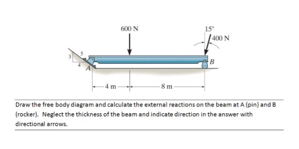
Draw the free-body diagram of the beam, which is pin- connected at A and rocker-supported at . B. 5-12 5.3 Equations of Equilibrium Free-Body Diagram Draw an outlined shape of the body. Show all the forces and couple moments acting on the body. ... the beam caused by the pin at B and the rocker at A. • Neglect the weight of the beam. Find : Solution Free-body diagram • Resolve the 600-N force into its Classify the beams shown in Figure 3.1 through Figure 3.5 as stable, determinate, or indeterminate, and state the degree of indeterminacy where necessary.. Fig. 3.1. Beam. Solution. First, draw the free-body diagram of each beam. To determine the classification, apply equation 3.3 or equation 3.4.. Using equation 3.3, r = 7, m = 2, c = 0, j = 3. Applying the equation leads to 3(2) + 7 > 3(3 ... A is a pin and b is a rocker. Draw the free body diagram for the beam. Draw a fbd of the 1000 lb weight. The above diagrams which show the complete system of applied and reactive forces acting on a body are called free body diagrams. The whole system of applied and reactive forces acting on a body must be in a state of equilibrium.
Draw the free-body diagram for the beam. A is a rocker and B is a pin. Draw the vectors starting at the black dots. The location and orientation of the vectors will be graded. The length of the... Draw the free-body diagram of the beam, which is pin 500 N connected at A and rocker-supported at B. 800 N⭈m SOLUTION B 5m A 8m 4m 5-9. Draw the free-body diagram of the jib crane AB, which is pin connected at A and supported by member (link) BC. Draw the free-body diagram of the beam which supports the 80-kg load and is supported by the pin at A and a cable which wraps around the pulley at D. Explain the significance of each force on the diagram. (SeeFig) View Answer. Draw the free body diagrams of the two spur gears shown in Figure. Possible free-body diagrams for two common situations are shown in the next two examples. Example 5.2.5. Fixed support. The cantilevered beam is embedded into a fixed vertical wall at A. Draw a neat, labeled, correct free-body diagram of the beam and identify the knowns and the unknowns. Solution.
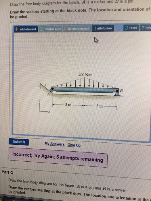
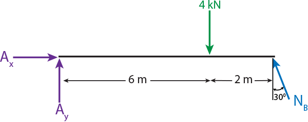
Part B Draw the free-body diagram for the beam. A is a rocker and B is a pin. Draw the vectors starting at the black dots. The location and orientation of the vectors will be graded.
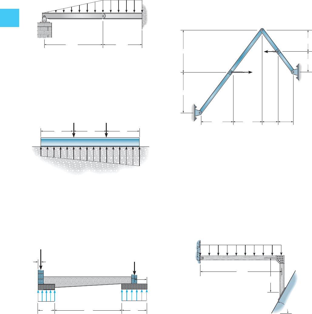
4.2 Free Body Diagrams The free body diagram is a depiction of an object or a body along with allthe external forces acting on it. • Choose and draw the body (with dimensions). Carefully define its boundaries. ... It is held in place by a pin at Aand a rocker at B.

Draw the free-body diagram for the beam. A is a rocker and B is a pin. Draw the vectors starting at the black dots. The location and orientation of the vectors will be graded. The length of the vectors will not be graded. Draw the free-body diagram for the beam. A is a rocker and B is a pin. Draw the vectors starting at the black dots.
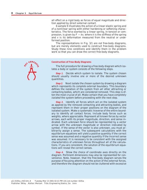
The above diagrams, which show the complete system of applied and reactive forces acting on a body, are called free body diagrams. The whole system of applied and reactive forces acting on a body must be in a state of equilibrium. Free-body diagrams are, consequently ,often called equilibrium diagrams. Drawing equilibrium diagrams and finding

There are a number of ways to draw pin connections Here is a pin connecting two members . 19 37 Free Body Diagrams Wednesday, October 3, 2012 New Support Conditions Pin Connection ! Another way Here is a pin support 38 Free Body Diagrams Wednesday, October 3, 2012 New Support Conditions Pin Connection ! On a pin, we know that there is an x and ...
Let us first draw a free body. Determine the horizontal and vertical components of reaction at the pin a and the reaction of the rocker b on the beam. Draw the free body diagram of the beam which is pin 500 n connected at a and rocker supported at b. Free body diagrams are consequently often called equilibrium diagrams.
CEE 211 - Statics & Dynamics The University of Michigan Fall 2014 Homework #4 (Due Wednesday, October 8th) Problem 1 (5 points) Draw the free-body diagram of the beam, which is pin connected at A and rocker-supported at B. Problem 2 (5 points) Draw the free-body diagram of the bar, which has a negligible thickness and smooth points of contact ...

Part B Draw the free-body diagram for the beam. A is a pin. Draw the vectors starting at the black dots. The location and orientation of the vectors will be graded. The length of the vectors will not be graded. Part C Draw the free-body diagram for the man and load. The man stands on a smooth floor.
Part B. Draw the free-body diagram for the beam. A is a rocker and B is a pin. Draw the vectors starting at the black dots. The location and orientation of the vectors will be graded. The length of the vectors will not be graded. Part D. Draw the free-body diagram for the beam. A is a rocker and B is a pin. Draw the vectors starting at the ...
Draw the free-body diagram of the beam, which is pin connected at A and rocker-supported at B. Free body diagram F.B.D may be defined as a graphical illustration, which shows all the forces acting ...

5—6. the free-body diagram af the crane boom AB which has a weight of 650 1b and center of gravity at G. The boom is supported by a pin at A and cable BC. The load of 1250 1b is suspended from a cable attached at B. Explain Lhc significance of each force acting on the diagram. (See Dr. Ahmed A. Abu-foul T.A: Eng. Waseem (Younis 30 sithBo COS So

Engineering Mechanics - Statics Chapter 5 Problem 5-10 Draw the free-body diagram of the beam, which is pin-connected at A and rocker-supported at B. Given: F = 500 N M = 800 N⋅ m a = 8m b = 4m c = 5m Solution: Problem 5-11 The sphere of weight W rests between the smooth inclined planes. Determine the reaactions at the supports.

List the Knowns/Unknowns and Draw the Free-body diagram of the beam, which is pin connected at A and rocker-supported at B 500 N 800 . List the Knowns/Unknowns and Draw the Free-body diagram of the bar, which has a negligible thickness and smooth points of contact at A, B, and C.

The beam shown below is supported by a pin at A and roller at B. Calculate the reactions at both supports due to the loading. 20 kN 40 kN 2 m 3 m 4 m A B EXAMPLE 1 . Draw the free body diagram: By taking the moment at B,


0 Response to "40 draw the free-body diagram for the beam. a is a rocker and b is a pin."
Post a Comment