38 115 volt motor wiring diagram
115v plug wiring diagram. Collection of travel trailer wiring schematic. The key is to make sure you connect the wires to the proper terminals in the plug. The larger prong is neutral and the smaller prong is the hot connector. Units with these plugs use between 110 and 120 volts standard household electricity. In addition, Wiring Diagram provides you with time frame in which the projects are to be completed. You'll be able to know precisely if the tasks needs to be completed, that makes it much easier for you to correctly control your time and effort. 3 4 Hp Ao Smith Electric Motor Wiring Diagram - Wiring Diagrams Hubs - A.o.smith Motors Wiring ...
115 Volt Ac Single Phase Motor Armature And Fields Wiring Diagram. conductor (rotor or revolving field). Armature coils. Revolving field coils As the PMG rotor rotates, it produces AC voltage in the PMG stator. Circuit: Generator. conductor (rotor or revolving field). Armature coils.

115 volt motor wiring diagram
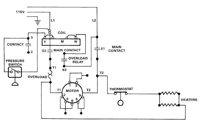
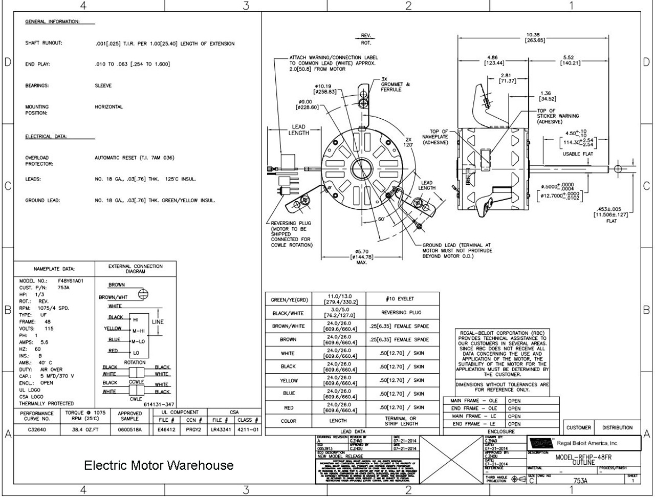
TERMINAL MARKINGS AND INTERNAL WIRING DIAGRAMS SINGLE PHASE AND POLYPHASE MOTORS MEETING NEMA STANDARDS See Fig. 2-11 in which vector 1 is 120 degrees in advance of vector 2 and the phase sequence is 1, 2, 3. (See MG 1-2.21.)* MG 1-2.24 Direction Of Rotation 115 volt dc motor wiring I just bought a Heath patten cutter with electrical problems . They were unknown to me when i got it but for what i payed i be alright . It has three fuses and two of those were missing that was the first sign . After taking the top off of the control box i found that the rheostat was fried . Motor wiring - L1 & L2, 115v. I'm wiring a new pump (USQ1072) for 115v operation The old pump's diagram (115v) has Line on L2. New pump's diagram suggests Line on L1 (Note: the text "Neutral Line" confuses me). I understand that it really doesn't make a difference, as long as my Line (in) is the side that is switched (which is is), so the motor ...
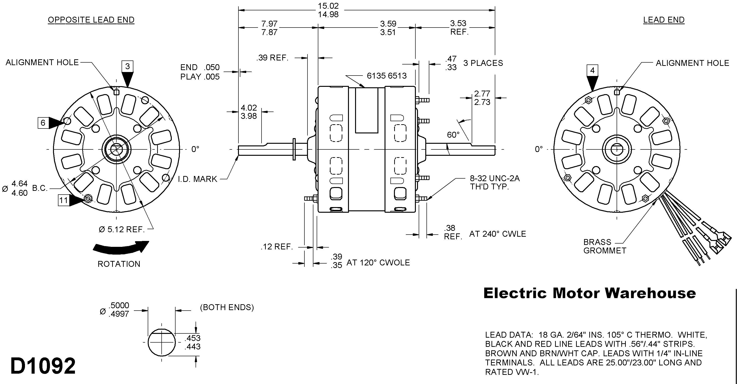
115 volt motor wiring diagram. Figure 2 - Wiring Diagram for Single Phase 1/3 - 2 HP Motors L1 A B L2 L1 A B L2 YELLOW 115 VOLT SINGLE PHASE LINE 230 VOLT SINGLE PHASE LINE WHITEGRAY RED TAN YELLOWWHITEGRAYRED TAN ® WIRING DIAGRAMS JET / CENTRIFUGAL MOTORS Flint & Walling | 95 North Oak Street | Kendallville, IN 46755 800-345-9422 | flintandwalling.com 115/230 Volt Motor Wiring Diagram - Database. Restoring electrical wiring, even more than some other household project is focused on protection. Install an outlet correctly and it's because safe as that can be; install it improperly and is actually potentially deadly. 115 230 Volt Wiring Diagram Schematic | Wiring Diagram - Century Ac Motor Wiring Diagram 115 230 Volts. Wiring Diagram comes with several easy to adhere to Wiring Diagram Guidelines. It's supposed to help each of the common person in creating a suitable system. These instructions will probably be easy to comprehend and apply. 115 230 Volt Motor Wiring Diagram. By Admin | January 3, 2018. 0 Comment. Doerr lr22132 motor wiring doityourself com community forums 3 hp special duty 3450 rpm 115 230 volt ac air compressor century b383 new arrivals www surpluscenter 2 sd need a guru pre 1950 antique fan collectors association afca dayton general purpose 4 capacitor start ...
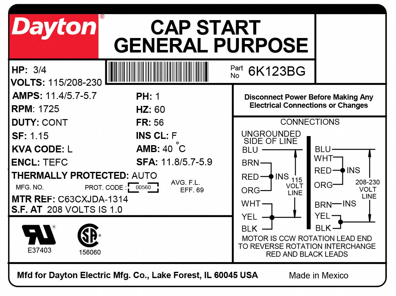
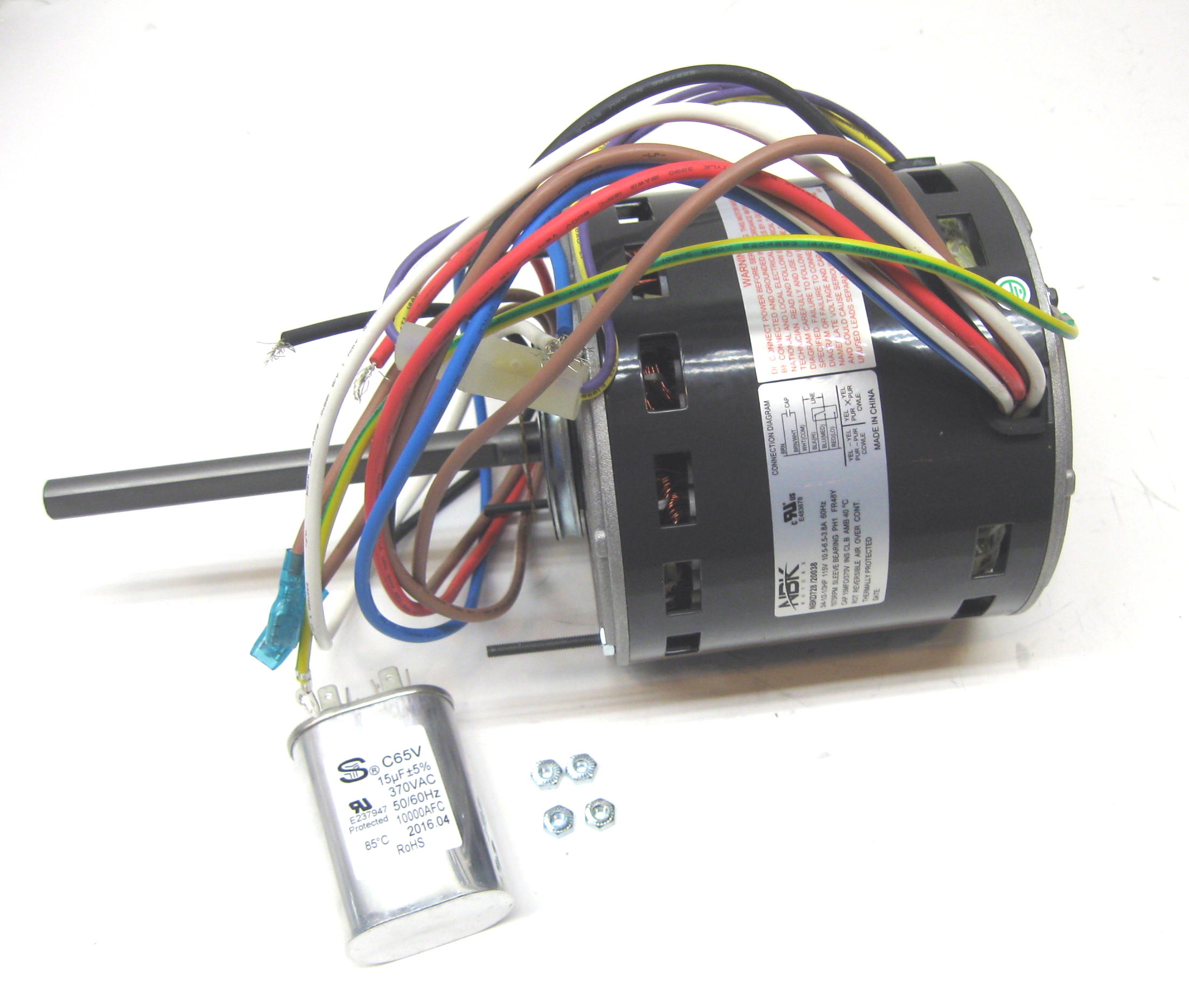
19.10.2018. 3 Comments. on Dayton 3/4 Hp 115v Electric Motors Wiring Diagram. Motors and Wiring Diagrams for Power Unit Machines. . All Wiring Should Be In Accordance with National Electrical Code Or Other Local Codes. Warning! . Dayton. 9Z 12 Volts DC, 1/8 HP, amps. 4Z 15/ Looking for DAYTON 3/4 HP Instant Reverse Motor, Nameplate RPM, Voltage ... 115 Volt Ac Motor Wiring - Wiring Diagrams Thumbs - Baldor Motor Wiring Diagram Wiring Diagram contains many in depth illustrations that show the link of assorted items. It contains guidelines and diagrams for various kinds of wiring techniques as well as other products like lights, home windows, etc. These diagrams are current at the time of publication, check the wiring diagram supplied with the motor. *NOTE: Refer to the motor manufacturer's data on the motor for wiring diagrams on standard frame Ex e, Ex d etc. motors. Inst Maint & Wiring.qxd 5/03/2008 10:02 AM Page 6 A.o.smith Motors Wiring Diagram - a o smith 1 2 hp motor wiring diagram, a o smith 2 speed motor wiring diagram, a o smith ac motor wiring diagram, Every electrical structure is composed of various diverse pieces. Each component should be set and connected with other parts in specific manner. Otherwise, the structure will not function as it should be.
115v Motor Wiring Diagram - wiring diagram is a simplified customary pictorial representation of an electrical circuit. It shows the components of the circuit as simplified shapes, and the capability and signal connections between the devices. A wiring diagram usually gives instruction virtually the relative slant and covenant of devices and ... This video explains how the wiring connections are made based on the wiring diagram provided with the motor. Name: single phase marathon motor wiring diagram - wiring diagram 115 volt motor single phase marathon awesome within electric basic diagrams 120; File Type: JPG; Source: trumpgrets.club; Size: 109.56 KB; Dimension: 800 x 563 Electric Chain Hoist Wiring Diagrams Products On American Crane. Electrical Tech Note 103. Need Wiring Diagram For Baldor 1hp Single Phase Motor. 2 Hp 3460 Rpm 115 208 230 Volt Ac Motor Techtop Motors Bl1 Rs Op 56 B C Cc Base Mount Single Phase Electrical Www Surpluscenter Com. 2 sd motor wiring need a 4 hp capacitor start nameplate rpm purple ...
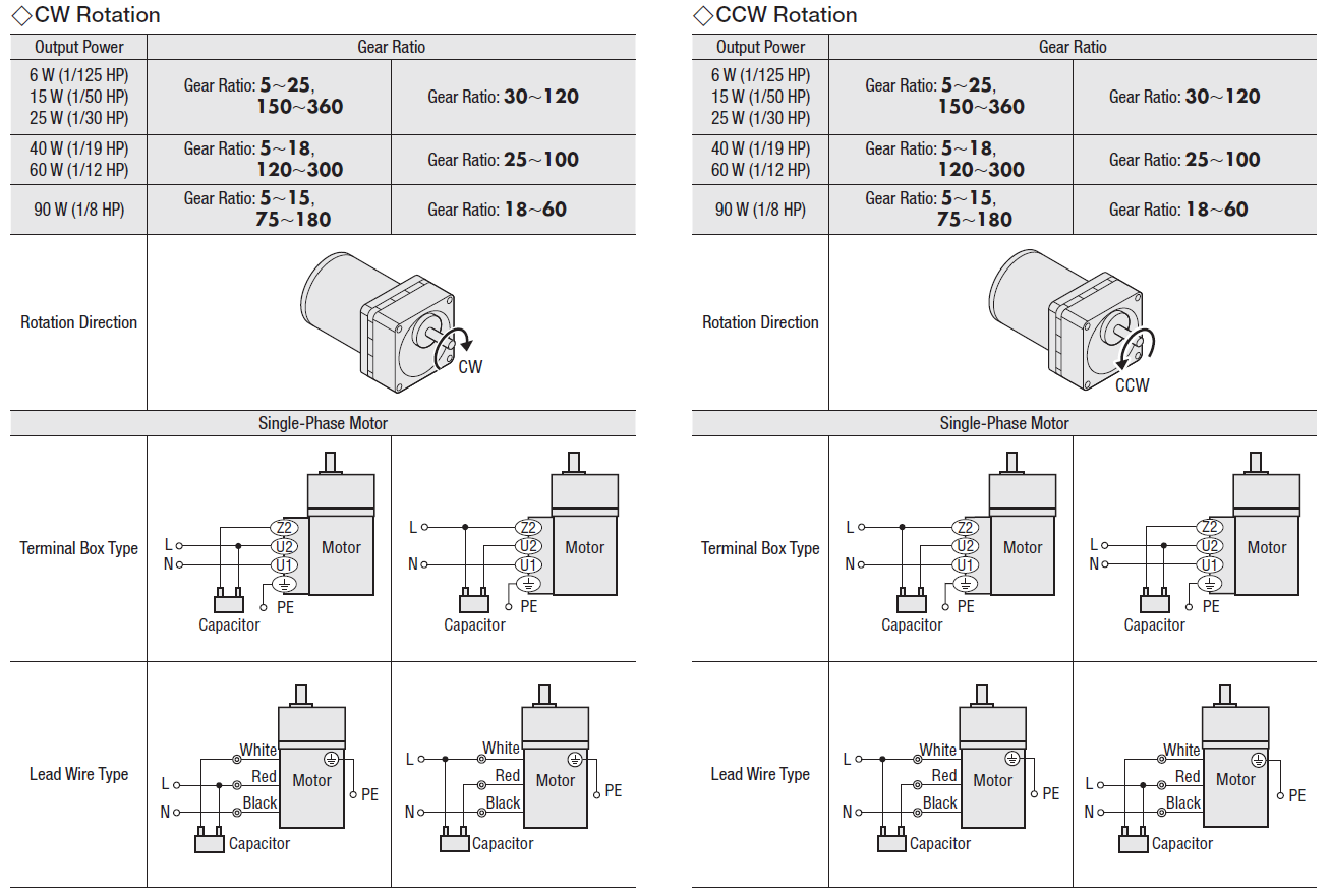
WIRING DIAGRAM IS-8 ( Rev. A ) (For "EM-1-3", and "EM-5" Two Pole, Single Phase, 3600 RPM, 115/230 volt, Explosion- Proof Motors, with Built-in On-Off Switch, Manufactured by Reliance Electric.) Direction of rotation considered as viewed facing the fan cover of the motor. COUNTERCLOCKWISE ROTATION IA INPUT LEAD L-2 INPUT LEAD CLOCKWISE ROTATION
ELECTRIC MOTOR DIAGRAMS. Internal Wiring Diagrams of Small and Fractional Horsepower Electric Motors. Split Phase Induction ... The starting capacitor is generally of the electrolytic type and may range from 80 to 300 micro-farads for 110 volt 60 HZ motors. These motors are good for applications requiring high starting torque such as ...

MOTOR WIRING DIAGRAM 904983 7 Lead, Dual Voltage (115 / 230) Single Phase with Thermal Protection Clockwise rotation facing shaft as shown Interchange leads T5 & T8 for counter-clockwise rotation Each lead may have one or more cables comprising that lead. In such case, each cable will be marked with the appropriate lead number ...
115/230 Volt Motor Wiring Diagram Source: s3.amazonaws.com 115/230 Volt Motor Wiring Diagram Source: static-resources.imageservice.cloud 6 Tips for power electrical wiring

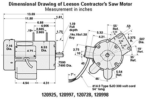
Electric Motor Wire Marking & Connections. For specific Leeson Motor Connections go to their website and input the Leeson catalog # in the "review" box, you will find connection data, dimensions, name plate data, etc. www.leeson.com Single Phase Connections: (Three Phase--see below) Single Voltage:

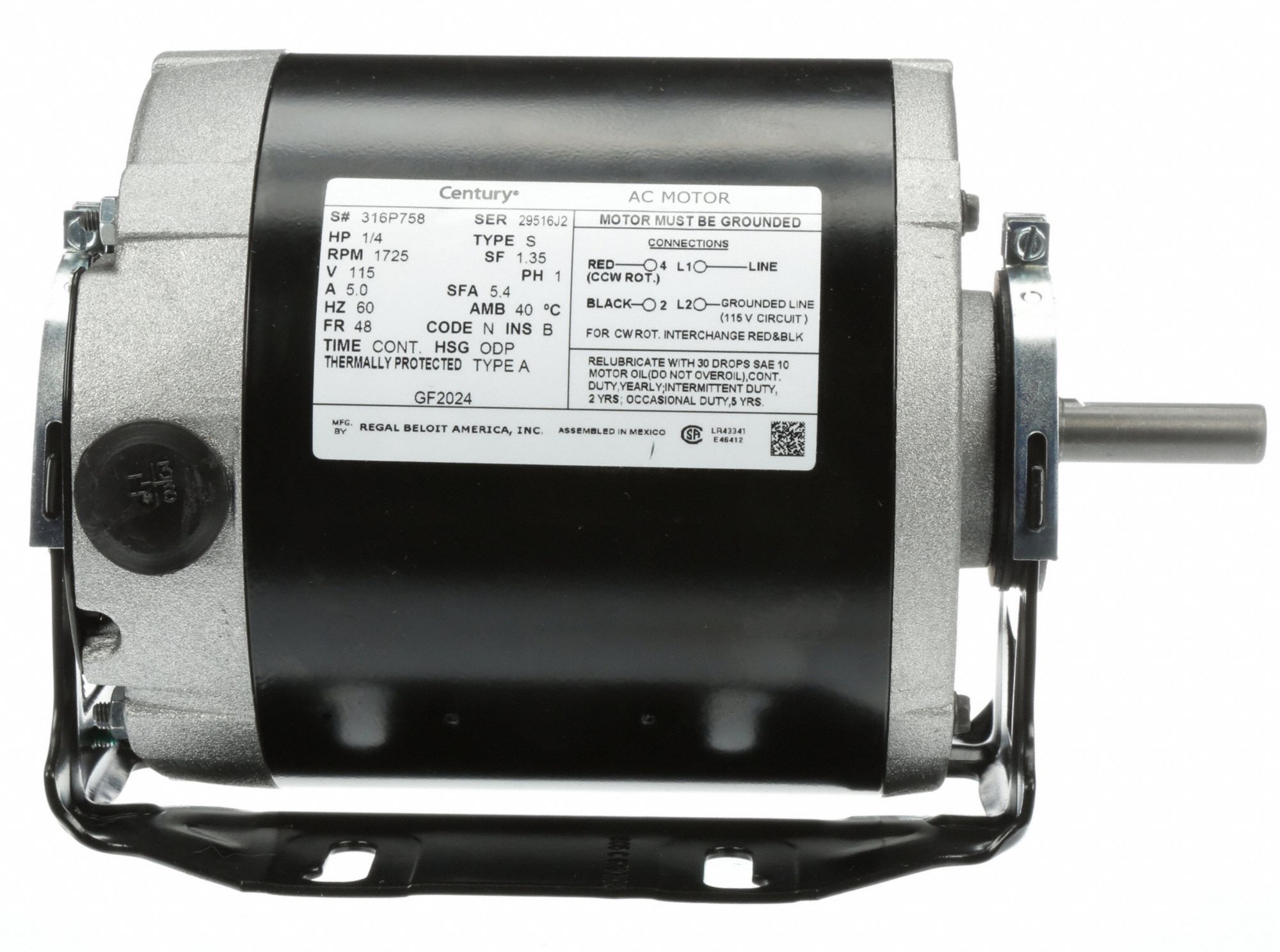
115 Volt Motor Wiring Diagram - Facbooik with Century Electric Motor Wiring Diagram by admin From the thousand photos on-line with regards to century electric motor wiring diagram, picks the best collections using greatest quality exclusively for you all, and now this photos is usually one of graphics choices in your ideal photographs gallery about Century Electric Motor Wiring Diagram.

115 Volt Motor Wiring Diagram. Effectively read a cabling diagram, one has to know how the particular components inside the method operate. For example , in case a module will be powered up and it also sends out a signal of fifty percent the voltage in addition to the technician would not know this, he'd think he offers a problem, as he would ...

115 Volt Ac Motor Wiring - Wiring Diagrams Thumbs - Baldor Motor Wiring Diagram The diagram offers visual representation of an electrical arrangement. On the other hand, the diagram is a simplified variant of this arrangement. This makes the process of building circuit easier.

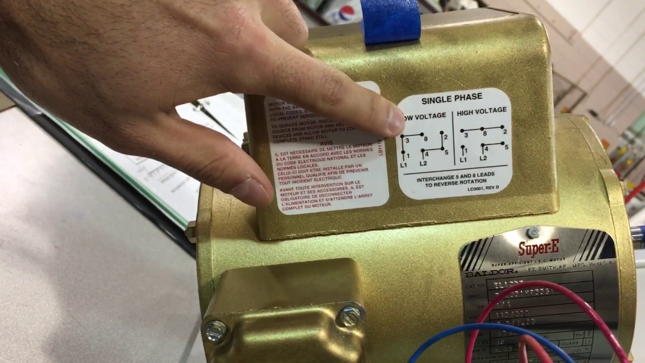
SINGLE PHASE MOTOR WIRING DIAGRAMS Single Voltage Motor 208-230V CCW CW L2 L1 T1 T8 T4 T5 T1 T5 T4 T8 Dual Voltage Motor 115V or 208-230V 208-230V or 460V Low Voltage High Voltage CCW CW CCW CW L2 T1 T3 T8 T2 T4 T5 T1 T3 T5 T2 T4 T8 L1 T1 T3 T8 T2 T4 T5 T1 T3 T5 T2 T4 T8 L1 L2 Dual Voltage Motor with Manual Overload (-MO)
I have a GE electric motor that can be used on 115 0r 230 volts. I want to use it on 230 volts. The diagram that shows connection for 115 or 230 is missing. The motor specs are: Model 5KC43MG40FX 3/4 … read more
1Ø WIRING DIAGRAMS (Form B) * Airflow direction base on left-hand blade installation. * Airflow direction base on left-hand blade installation. Airflow Airflow Airflow Airflow * * These diagrams are current at the time of publication, check the wiring diagram supplied with the motor. Inst Maint & Wiring_5.qxd 20/11/2015 11:37 AM Page 7
Motor wiring - L1 & L2, 115v. I'm wiring a new pump (USQ1072) for 115v operation The old pump's diagram (115v) has Line on L2. New pump's diagram suggests Line on L1 (Note: the text "Neutral Line" confuses me). I understand that it really doesn't make a difference, as long as my Line (in) is the side that is switched (which is is), so the motor ...
115 volt dc motor wiring I just bought a Heath patten cutter with electrical problems . They were unknown to me when i got it but for what i payed i be alright . It has three fuses and two of those were missing that was the first sign . After taking the top off of the control box i found that the rheostat was fried .

TERMINAL MARKINGS AND INTERNAL WIRING DIAGRAMS SINGLE PHASE AND POLYPHASE MOTORS MEETING NEMA STANDARDS See Fig. 2-11 in which vector 1 is 120 degrees in advance of vector 2 and the phase sequence is 1, 2, 3. (See MG 1-2.21.)* MG 1-2.24 Direction Of Rotation


0 Response to "38 115 volt motor wiring diagram"
Post a Comment