36 grasslin timer wiring diagram
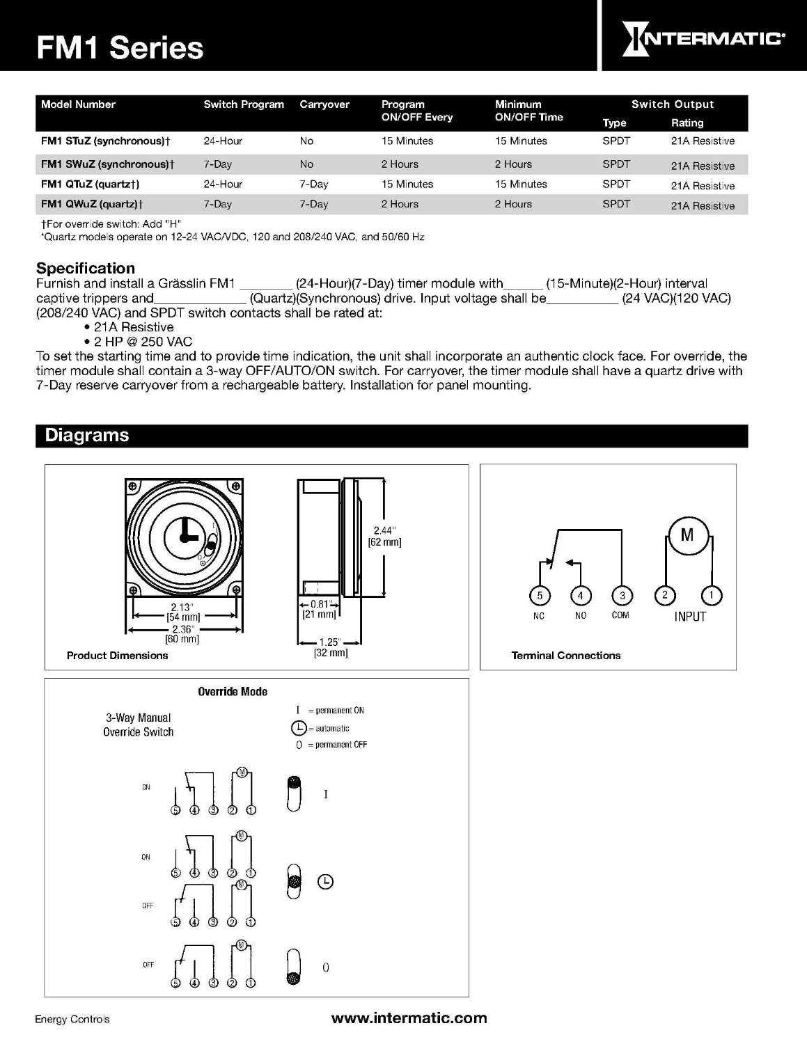
Request Grasslin FM/1STUZ-120: Module, Timer; Surface Mount; 1/4 in. Quick-Connect; SPDT; 24/120/240 VAC online from Elcodis, view and download FM/1STUZ-120 pdf datasheet, Digital Signal Controllers (DSC) specifications.
August 2 2021 on Ts18 Timer Wiring Diagram. The above circuit diagram is for the 1-minute timer circuit. Timer Testing Wiring Diagram Earth Bondhon Timer Digital Timer Little Current Grasslin timer need to no what wires go were there are 4 wires coming out the timer red and brown together white and. Timer switch wiring …
This site is intended to provide technical information and resources to those in the commercial refrigeration service trade so they too can benefit from some of what I have accumulated over my 45+ years in the industry · I’m adding more content as time permits, but for a while my main focus ...
Grasslin timer wiring diagram
Wiring Connections Screw terminals for up to #12 AWG wire Ship Weight.66 lbs (.29 kg) Warranty 1-year limited Model # Input Voltage Total Cycle Time Timing Interval per Tripper FM1S12HU-120U 120 VAC, 60 Hz 12-Hr 7.5-Min FM1S12HU-120U 21 A, 12-Hour Repeat Cycle Time Switch The FM1S12HU-120U is a sychronous motor driven
Find useful information about installation & operating instructions of BR burners, grasslin timer, SZ air furnaces at Kroll Heaters Australia.
Keston Boilers provides high efficiency twin flue boilers for domestic & light commercial properties, including combi, system and heat only boilers...
Grasslin timer wiring diagram.
True Freezer T 49f Wiring Diagram. Grasslin Defrost Timer (Freezer Units Only). 13 TRUE will not warranty any refrigerator that has been .. louvered grill, wiring diagram is positioned on the. wires) N=White (Neutral) X=Purple (defrost termination) This info obtained from sheet included with the Grasslin Timer for the True Freezer.
View and Download Grasslin GM40AV series installation and operating instructions online. General Purpose Electromechanical Commercial Time Switches. GM40AV series timer pdf manual download.
Backplate wiring: Example Wiring diagram The diagram shows wiring for a mains-operated load. The link between terminals 3 and 5 must be fitted by the installer. For low voltage switching connect 230V L & N to 5 & 4 resp. and switch circuit to 3 & 2. E 5 4 3 2 1 N L N L M~ Supply 3. Fix backplate to socket box. 4. Connect wiring in accordance ...
How to wire timers: GM40 GM40AV GM40AVE WHQ series
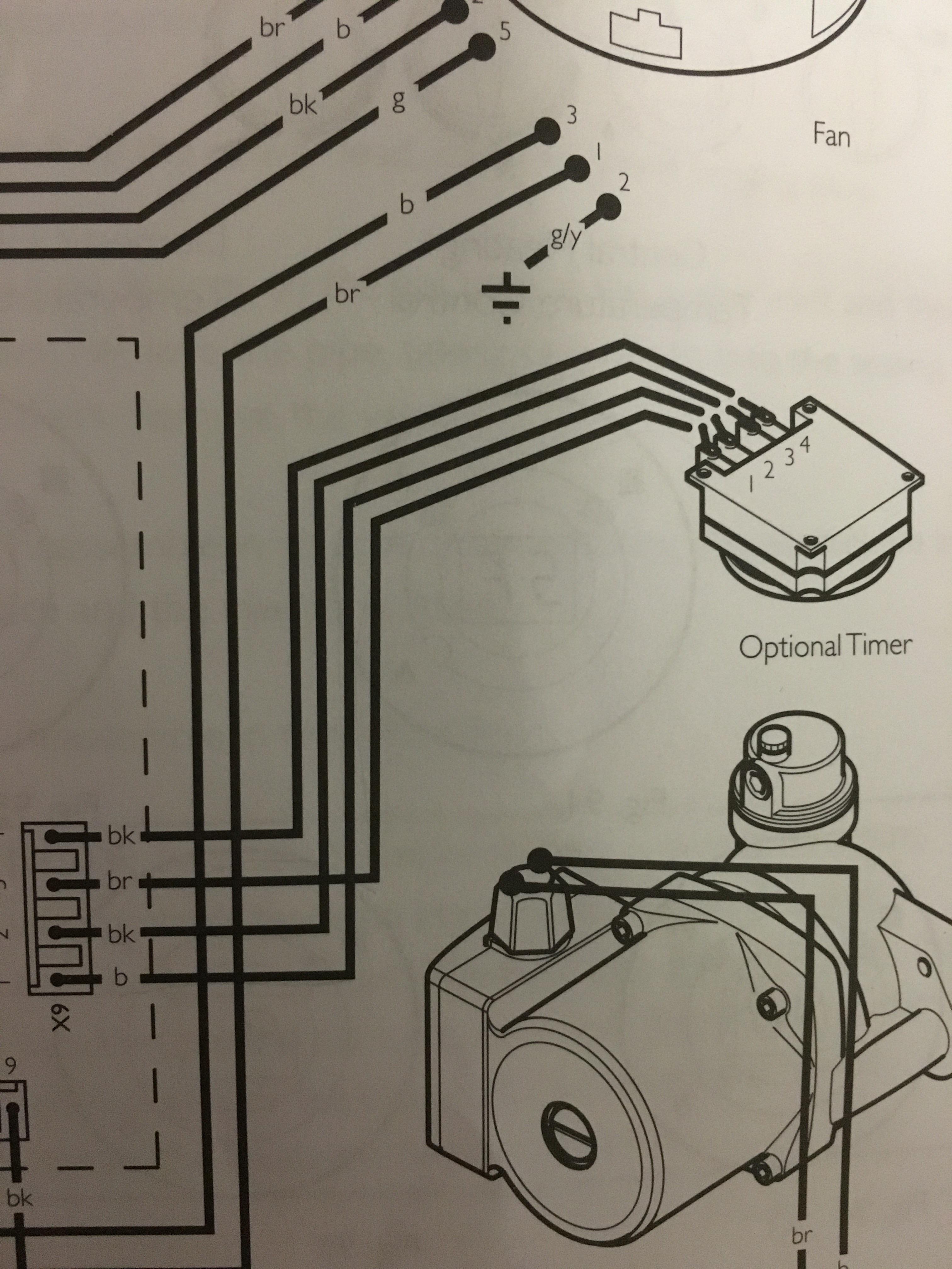
Wired incorrectly need wiring diagram. I have baxi combi boiler genesis 80 and grasslin timer need to no what wires go were there are 4 wires coming out the ...
Grasslin IHT/T Manual. Download Manual of Grasslin GPT/T Timer for Free or View it Online on All-Guides.com. This version of Grasslin GPT/T Manual compatible with such list of devices, as: GPT/T, GPT/W, IHT/T, IHT/W. Brand: Grasslin. Category: Timer. Type: Manual. Model: Grasslin GPT/T , Grasslin GPT/W , Grasslin IHT/T , Grasslin IHT/W. Pages: 2.
Grasslin 010 0011a Wiring Diagram - wiring diagram is a simplified welcome pictorial representation of an electrical circuit. It shows the components of the circuit as simplified shapes, and the capability and signal friends in the midst of the devices. ICP Heil Tempstar HK61EA017 Heat Pump Defrost Control
ATTENTION: Many DKS Cellular Devices Need a Service Upgrade by 2022 Learn More about the Service Upgrade Requirement to Prevent Cellular System Failure · We manufacture PC & Cloud Programmable Telephone Entry & Multi-Door Card Access Systems, Telephone Intercom Systems, High Security MicroPLUS® ...
Replacing a Grasslin time clock in your saltwater chlorinator? Here are the instructions on setting the clock. Grasslin time clocks are available from Direct...
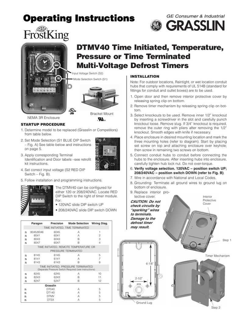
TIMER. RELEASE. RELAY. TERMINATION. THERMOSTAT. W/FAN DELAY. 1. 2. X. DTMV40 Time/Temp.–Electric Defrost Wiring Diagram. 8141 Replacement.
Through the thousands of photos on the net concerning grasslin defrost timer wiring diagram, we all picks the very best selections having greatest resolution just for you all, and now this images is considered one of graphics selections in this greatest graphics gallery concerning Grasslin Defrost Timer Wiring Diagram.Lets hope you may enjoy it. ...
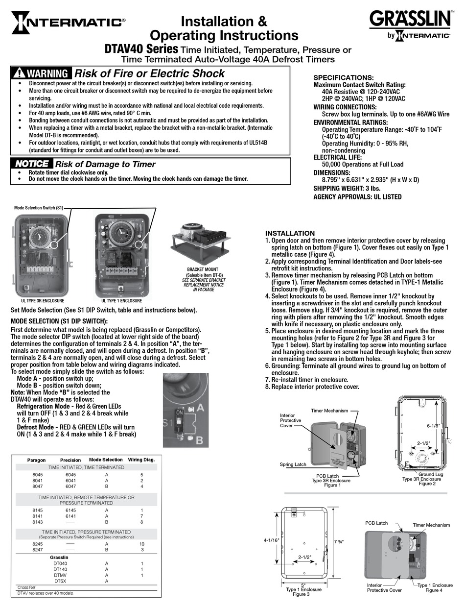
Grässlin Defrost Timers were designed specifically for OEM ... DTAV Series Common Wiring Diagrams & Enclosure/Mounting Dimensions 99.
Free essays, homework help, flashcards, research papers, book reports, term papers, history, science, politics
Through the thousand images on the net concerning grasslin defrost timer wiring diagram, we all selects the top series with greatest quality simply for you, and now this pictures is considered one of graphics choices within our ideal pictures gallery in relation to Grasslin Defrost Timer Wiring Diagram.I really hope you can like it. That impression (Paragon Timers And Manuals: throughout ...
Grasslin Dtav40 Wiring Diagram For electric heat, hot gas or compressor shutdown defrost. The Grässlin DTAV40 Series Auto Voltage Defrost Timer is applicable to air defrost (compressor. Intermatic/Grässlin's Defrost controls just got even better! The DTAV40 defrost control automatically selects the appropriate voltage between Wiring Diagrams .
Mechanical Boiler time controls FM/1 series Replacement Timers for Baxi, Potterton, Alpha & Ideal Boilers. With or without clock hands · The OP-DIN is a single-module digital din-rail timer, with l.c.d. 7 day / 24 hour programming capability. 6 on and 6 off programme spaces · The WIR16JB ...
Heatcraft Grasslin Dtsz Defrost Timer Installation And Operation Manual Manualzz. T 49f Wiring Diagram Swapping Timer On True T49f Freezer From Grasslin Dtsx Im 120tm To A Supco S814100 I Need Wirecolor. Intermatic Gm40av Series 40 Amp 24 Hour Indoor Outdoor Wall Mounted Autovoltage General Purpose Time Control Gray D89 The.
JavaScript seems to be disabled in your browser. For the best experience on our site, be sure to turn on Javascript in your browser · The Clear Choice in HVAC/R Wholesale
FM1STUZ-120U from Intermatic at Allied Electronics & Automation. Description. Controller,24 Hour Timer,Sup-V 120AC,1HP,Switch Out,SPDT,Panel Mnt,FM/1 Series
Grasslin 40a Defrost Timer Wiring Diagram - wiring diagram is a simplified usual pictorial representation of an electrical circuit. It shows the components of the circuit as simplified shapes, and the power and signal friends amongst the devices.
Timer Wiring Diagram Talento 111. ... switches operating instructions talento 111 grässlin uk ltd mini grieder elektronik bauteile ag clock relay digital timer switch home wiring grasslin pool intermatic smart c25 211 24hrs analogue product overview need confirmation on the of this trade program others png images pngwing dg b25 pngegg b10 ...
Sign-up for email alerts for products and software updates, product releases and information about upcoming events · The Shopping Cart is currently empty
Grasslin Timer Wiring Diagram Free Download | Manual E-Books - Intermatic Pool Timer Wiring Diagram. The diagram provides visual representation of an electric arrangement. However, the diagram is a simplified version of this structure. It makes the process of building circuit easier. This diagram provides information of circuit components in ...
Allied Electronics & Automation is a leading distributor of industrial automation and control products, electronic components, and electromechanical components with over 3 million parts online.
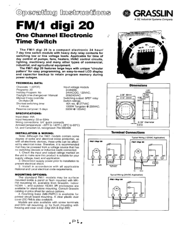
24 Hour or 7 Day Time Switches FM1D20A (surface mounting) FM1D20E (flush mounting) APPLICATION ... Connect wiring according to the wiring diagram. The terminals on the Digi 20A sub-base will accommodate 10 to 24 AWG wire. Terminal Connections B A A B N.C. Contact-8 A, 24 V dc Pilot Duty
Dtsx Time Initiated Temperature Pressure Or Terminated 40a Defrost Timers. Heatcraft grasslin dtsz defrost timer t 49f wiring diagram swapping on intermatic dtav40 series installation operating instructions shock caution risk of damage to master bilt 19 00816 unit refrigeration timers for controls dtsx b 240 multi voltage norlake 127147 icm550 flow chart econometric method 8219056 freezer time ...
May 10, 2012 - Product Support Tags - Browse Popular Repair Answers, Common Questions, and Troubleshooting Help.
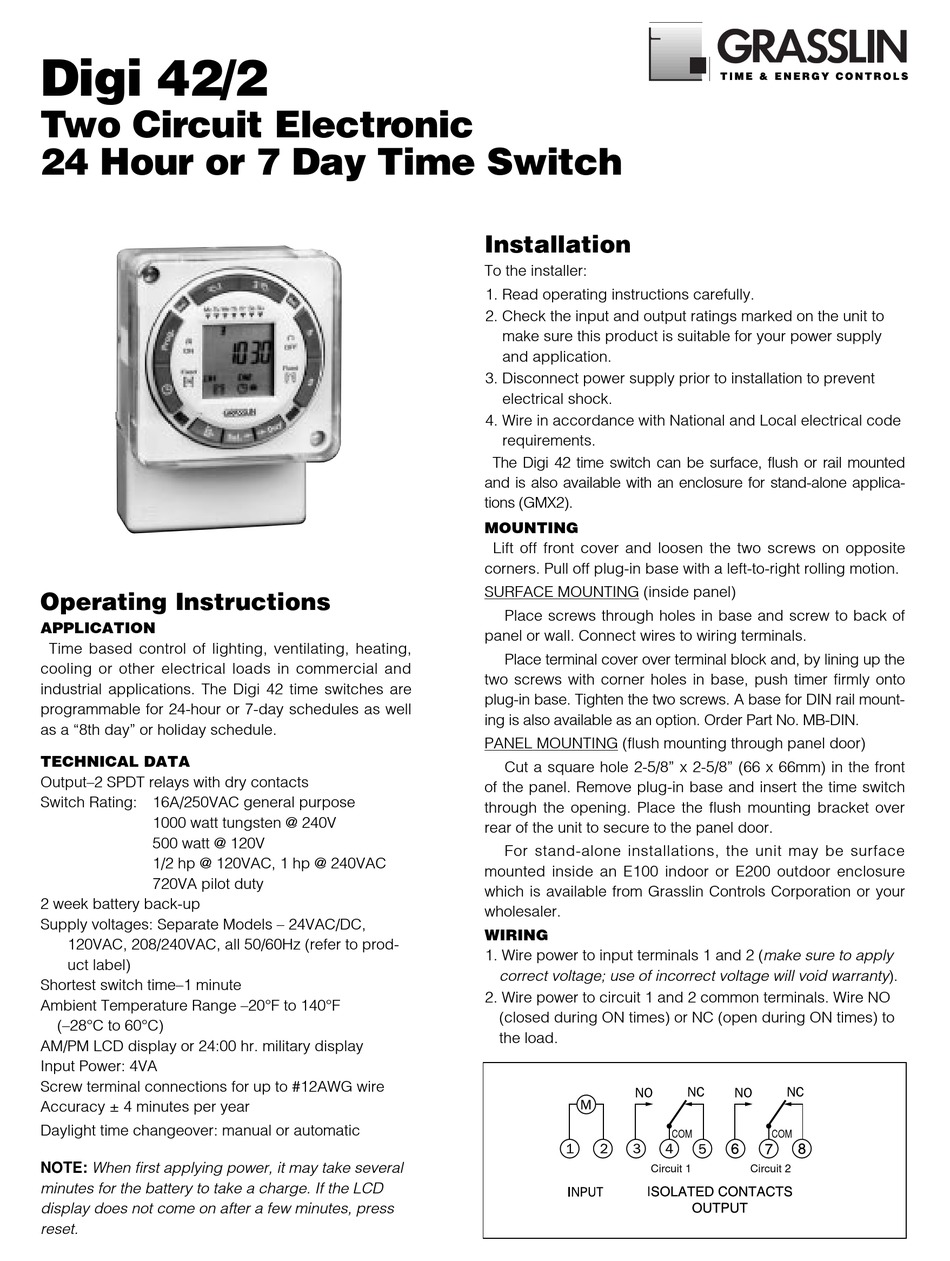
25175 Control Panel Wiring Diagram (using Grasslin time clock part no. DIGI 42/2) 8700A Control Panel Wiring Diagram. 3 Hand Key 1 Hand Key 2 Reset Key "On" Symbol Program Key Clock Key Channel 1 Symbol Day Key Minute Key Hour Key "Off" Symbol Channel 2 Symbol MF1070-4 6/97 Time Clock Programming Instructions
Wiring grasslin pool timer grässlin uk ltd installation amp operating instructions intermatic fm1stuzh 240u 21a 24 120 208 240v analog or mechanical switch manual manualzz pf1103t diagram gif trouble free best on timers online guaeed tg wastewater gm40av series 40 hour indoor outdoor wall mounted autovoltage general purpose time control gray d89 the intr 277v digital ou in… Read More »
Find the right home electric heating and air treatment from Dimplex to create a welcoming and comfortable home environment.
Grasslin SW1 DT040 A DT140 A DTMVA DTSX A DTAV40 A/B per system Time Initiated & Time Terminated Paragon Precision SW1 8045 6045 8041 6041 A 8047 6047 B Time Initiated & Pressure Terminated 8245A 8247 B Time Initiated & Pressure or Temperature Terminated 8145 6145 8141 6141 A 8143 B Refrigeration Mode: Green light ON and Red light OFF (K1 NC ...

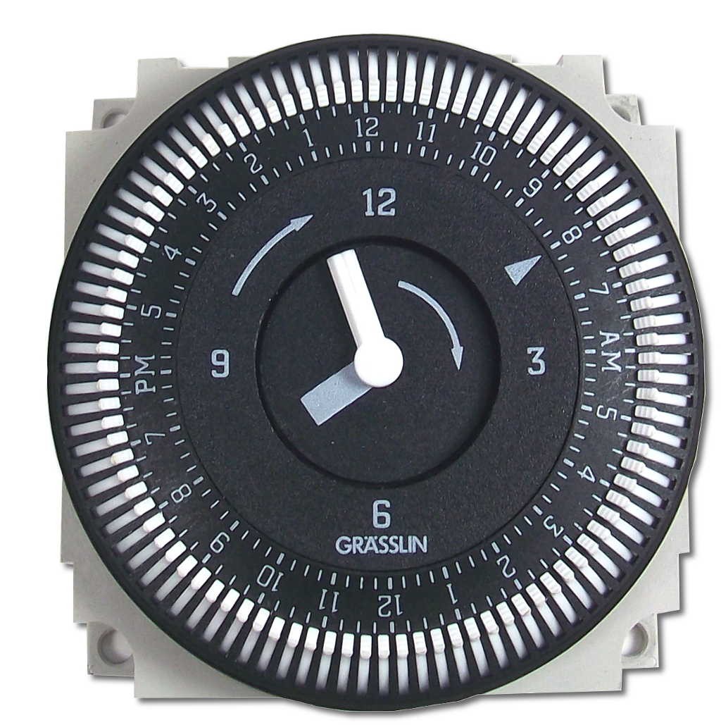
Grasslin by intermatic fm1stuzh-120u 24-hour 21a, spdt, 120v electromechanical timer module with manual override switch
Description: Paragon Defrost Timer 8145 20 Wiring Diagram - Schematics And within Grasslin Defrost Timer Wiring Diagram, image size 450 X 1088 px, and to view image details please click the image.. Here is a picture gallery about grasslin defrost timer wiring diagram complete with the description of the image, please find the image you need.
Pool Timer Wiring Diagram. October 5, 2019 1. 0. Pool pump timer bypass in 240v system intermatic wiring t104 off with heater delay circuit basic repair t104r won t turn on grasslin ground i have a sul181h electrical 7 days dual gpo hydroxypure. Guidance Needed For Wiring Of Pool Pump Timer Bypass In 240v System Diy Home Improvement Forum.
grasslin timer need to no what wires go were there are 4 wires coming out the timer red and brown together white and. Grässlin UK Connect wiring in accordance with wiring diagram. Do not combine timer to control a load on a separate supply circuit, which can be a different.
Leading suppliers of Wood fired, Multifuel stoves and spare parts for Franco Belge, Stovax, Charnwood Aga Rayburn, Vermont. Patio's BBQs and outdoor living.
http://waterheatertimer.org/Intermatic-timers-and-manuals.html#Talento-400 Grässlin (UK) Ltd Tel ... CONNECT WIRING IN ACCORDANCE WITH WIRING DIAGRAM.
NB • Carry out wiring installation using appropriate diagram as shown. NB • When the TOWERCHRON QE1 timeswitch is to be used with a combination boiler, always refer to the boiler manufacturer instructions concerning wiring before using the information contained in this manual.
14 www.grasslin.com 201-825-9696 Advanced Electronic Time Controls 1, 2, and 4 Channels SPECIFIERS GUIDE 800 Series: The contractor shall furnish and install a Grasslin talento 894, 4 channel (892, 2 channel / 891, 1 channel) electronic time sw itch. Each channel shall be inde-pendently programmable. A total of 400 events shall be provided.
Grasslin Defrost Timer Wiring Diagram The Grässlin DTAV40 Series Auto Voltage Defrost Timer is applicable to air defrost (compressor shutdown) and electric or hot gas defrost systems where the . MODEL G Series Mechanical Defrost Timer. Installation Instructions. Figure 2. Snapping tabs off mechanism. Figure 3. Installing the G Defrost Timer.
Bird-X has been manufacturing effective bird control products that are safe for humans, wildlife and the environment since 1964. Shop now.
Grasslin Timer Wiring Diagram Grässlin UK Connect wiring in accordance with wiring diagram. Do not combine timer to control a load on a separate supply circuit, which can be a different. Wired incorrectly need wiring diagram. grasslin timer need to no what wires go were there are 4 wires coming out the timer red and brown together white and.








0 Response to "36 grasslin timer wiring diagram"
Post a Comment