41 iron iron carbide phase diagram
The primary phase of low-carbon or mild steel and most cast irons at room temperature is ferromagnetic α-Fe. It has a hardness of approximately 80 Brinell. The maximum solubility is about 0.02 wt% at 727 °C (1,341 °F) and 0.001% carbon at 0 °C (32 °F). When it dissolves in iron, carbon atoms occupy interstitial "holes". Being about twice the diameter of the tetrahedral hole, the carbon ... This video provides an explanation the Iron- Iron Carbide Phase diagram.
Cementite or iron carbide, is very hard, brittle intermetallic compound of iron & carbon, as Fe 3 C, contains 6.67 % C. It is the hardest structure that appears on the diagram, exact melting point unknown. Its crystal structure is orthorhombic. It is has low tensile strength (approx. 5,000 psi), but high compressive strength.

Iron iron carbide phase diagram
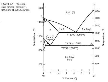
2) Cementite : Iron carbide(Fe 3 C), contains 6.67% wt. C Orthorhombic structure, HARD and BRITTLE 3) Pearlite : Phase mixture (ferrite+cementite), Lamellar structure, contains ~0.8% wt. C Produced from austenite decomposition 4) Austenite : o g-iron, Solid solution, stable at higher temperatures (>727 C) o Max. Check Pages 1 - 7 of The iron-iron carbide (Fe-Fe3C) phase diagram in the flip PDF version. The iron-iron carbide (Fe-Fe3C) phase diagram was published by on 2015-05-11. Find more similar flip PDFs like The iron-iron carbide (Fe-Fe3C) phase diagram. Download The iron-iron carbide (Fe-Fe3C) phase diagram PDF for free. The iron-iron carbide phase diagram (Fig. ) furnishes a map showing the ranges of compositions. and temperatures in which the various phases such as austenite, ferrite, and cementite are present in. slowly cooled steels. The diagram covers the temperature range from 60O0C to the melting point of.
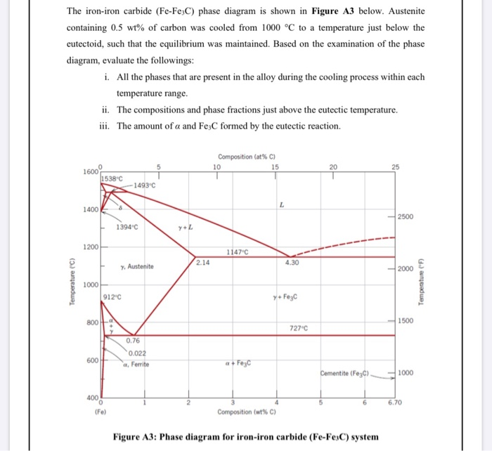
Iron iron carbide phase diagram. Phase diagrams are classified according to the number of component present in a particular system. Phase diagram -Useful information Important information, useful in materials development and selection, obtainable from a phase diagram: ... reactions: iron. system ... Answer: Iron loses its magnetic nature at 1043K and early investigators found that this loss is due to phase transformation and named the paramagnetic iron( above 1043K) as beta iron.Later it was found that the loss in magnetic nature is not because of phase transformation and they removed the be... Example: Phase Equilibria For a 99.6 wt% Fe-0.40 wt% C at a temperature just below the eutectoid, determine the following a) composition of Fe 3C and ferrite (α) b) the amount of carbide (cementite) in grams that forms per 100 g of steel c) the amount of pearlite and proeutectoid ferrite (α) Iron can exist in more than one crystalline form, so an engineer should know at what temperature and composition, which phase exist? What will be the properties? All the important concepts of Iron Iron Carbide phase diagram are explained. Phases like, Ferrite, Austenite, Cementite are explained in details.
The part of iron-carbon alloy system diagram between pure iron and an interstitial compound, iron carbide (Fe3C), containing 6.67 percent carbon by weight is called iron-iron carbide equilibrium diagram. In fact, the compound iron carbide decomposes into iron and carbon (graphite). What does the iron carbon phase diagram show? Answer: Iron-Iron carbide phase diagram is the single most important phase diagram for a materials scientist and most probably one of the very few phase diagrams which are studied for the maximum amount of time of any materials science student. Courtesy: The Iron Carbon Phase Diagram Now, let's... The Iron-Iron carbide phase diagram is shown below. This phase diagram presents the phases present at various temperatures for very slowly cooled iron-carbon alloys with up to 6.67% carbon. The pure iron exists in three allotropic forms (i.e, α-iron, γ-iron, and δ-iron) before it melts. At room temperature, the stable form called ferrite ... The iron-iron carbide phase diagram is shown in the Animated Figure 9.24. Question: Compute (a) the mass fractions of proeutectoid ferrite and (b) the mass fraction of pearlite that form in an iron-carbon alloy containing 0.30 wt% C. The iron-iron carbide phase diagram is shown in the Animated Figure 9.24.
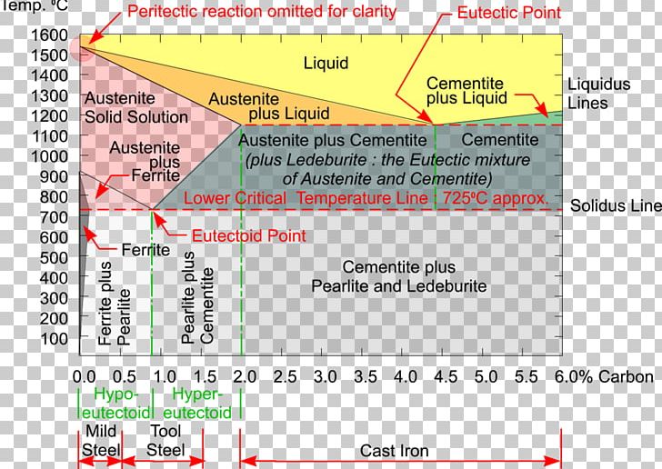
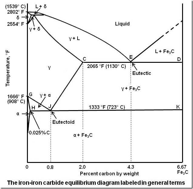
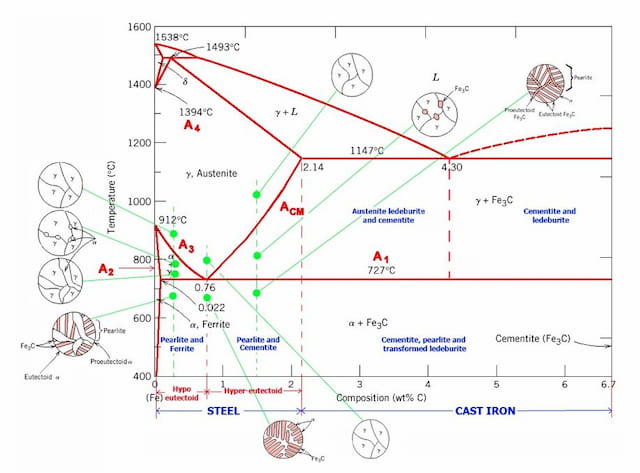
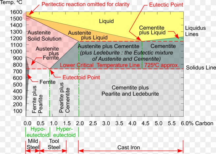
Fig 1: Fe-Fe 3 C Phase Diagram (clickable), Materials Science and Metallurgy, 4th ed., Pollack, Prentice-Hall, 1988 . Figure 1 shows the equilibrium diagram for combinations of carbon in a solid solution of iron. The diagram shows iron and carbons combined to form Fe-Fe 3 C at the 6.67%C end of the diagram. The left side of the diagram is pure ... Phases in Fe–Fe. 3. C Phase Diagram. ¾α‐ferrite‐solid solution of C in BCC Fe. •Stable form of iron at room temperature. • Transforms to FCC g‐austenite at 912 °C ¾γ‐austenite‐solid solution of C in FCC Fe. • Transforms to BCC δ‐ferrite at 1395 °C •Is not stable below the eutectic temperature (727 °C) unless cooled rapidly. ¾δ‐ferritesolid solution of C in BCC Fe. This Video DescribesDifferent phases in IRON - IRON CARBIDE system.3 Invariant reactions in the diagram. The part of iron-carbon alloy system diagram between pure iron and an interstitial compound, iron carbide (Fe3C), containing 6.67 percent carbon by weight is called iron-iron carbide equilibrium diagram. It may be noted that though it is called as equilibrium diagram, it is not a true equilibrium diagram, since equilibrium implies no change of phase with time. In fact, the compound iron carbide decomposes into iron and carbon (graphite). This decomposition takes a very long time at room temperature, even at 1300°F, it takes several years to form graphite. The iron carbide is called metastable phase. Therefore, iron-iron carbide diagram even though technically represents metastable conditions, can be considered as representing equilibrium changes, under conditions of relatively slow heating and cooling. Above figure shows iron-iron carbide equilibrium diagram labeled in general terms with Greek letters to represent the solid solutions. However, it is common practice to give special...
Ironcarbon Phase Diagram Png Images Pngwing
The iron-iron carbide phase diagram is shown in the Animated Figure 9.24. (a) How many kilograms of proeutectoid ferrite form? (b) How many kilograms of eutectoid ferrite form? kg (c) How many kilograms of cementite form? kg . This problem has been solved!

Gate Metallurgical Engineering Iron Iron Carbide Phase Diagram
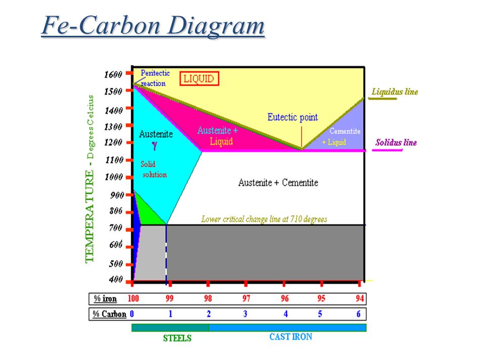
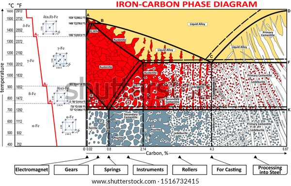
THE IRON-IRON CARBIDE DIAGRAM A map of the temperature at which different phase changes occur on very slow heating and cooling in relation to Carbon, is called Iron- Carbon Diagram. Iron- Carbon diagram shows the type of alloys formed under very slow cooling, proper heat-treatment temperature and how the properties of steels and cast irons can ...
Iron Carbon Phase Diagram
This iron carbon phase diagram is plotted with the carbon concentrations by weight on the X-axis and the temperature scale on the Y-axis. The carbon in iron is an interstitial impurity. The alloy may form a face centred cubic (FCC) lattice or a body centred cubic (BCC) lattice. It will form a solid solution with α, γ, and δ phases of iron.

Iron Carbon Phase Diagram
Sep 21, 2014 · Contents • Lever’s Rule • Eutectic Reactions • Eutectoid Reactions • Peritectic Reactions • Cu-Ni Phase Diagram • Pb-Sn Phase Diagram • Al-Si Phase Diagram • Iron-Iron Carbide Diagram 4. Component and System • A component is defined as pure metals of which an alloy is composed.

Tpce Mech Books Iron Carbon Phase Diagram Or Equilibrium Diagram
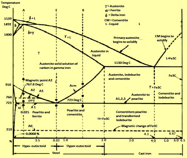
Iron-Iron Carbide Phase Diagram | Material Engineering. The Iron-Iron carbide (Fe-Fe 3 C) is defined by five individual phases and four invariant reactions. Five phases are- α-ferrite (BCC) Fe-C solid solution, γ-austenite (FCC) Fe-C solid solution, δ -ferrite (BCC) Fe-C solid solution, Fe 3 C (iron carbide) or cementite – an inter- metallic compound and liquid Fe-C solution.
Fe Carbon Phase Diagram Ppt Video Online Download
Mechanical Engineering questions and answers. 1. Describe the limitations of the iron-iron carbide equilibrium phase diagram when applied to determine microstructure development during heat treatment. Which phases and microconstituents are not found in the diagram? (6 points)
Solved The Iron Iron Carbide Fe Fe3c Phase Diagram Is Chegg Com
Note: Download Iron Carbon Phase Diagram PDF at the end of the article. The right-hand side of the iron-iron carbide phase diagram involves the phase iron carbide, or Fe 3 C, often called cementite. Cementite is a hard, brittle material with a complex crystal structure.

Iron Carbon Phase Diagram Cementite Iron Angle Electronics Text Png Pngwing
Hello everyone in this video i will show you how to read or how to use iron iron carbide equilibrium diagram in metallurgical and materials systems. this dia...

Iron Iron Carbide Phase Diagram 234 Download Scientific Diagram
The Iron-Iron Carbide Diagram • A map of the temperature at which different phase changes occur on very slow heating and cooling in relation to Carbon, is called Iron- Carbon Diagram. • Iron- Carbon diagram shows - The type of alloys formed under very slow cooling, - Proper heat-treatment temperature and

Refer To The Iron Iron Carbide Phase Diagram T 730c And 5w C A What Is The Relative Amount Of The Alpha Ferrite Phase B What Is The Carbon Composition By Wt Of The Austenite Gamma
Iron carbide (Fe 3 C) is often labeled as the uncorroded portion of the steel. It is primarily associated with mild steels having a high carbon content and a ferritic-pearlitic microstructure. During corrosion of such steel, the ferrite phase dissolves and a porous iron carbide network is exposed (see Fig. 7.6).Given that iron carbide is an electronic conductor, this porous network serves as ...
Iron Carbon Phase Diagram Steel Cementite Png Clipart Angle Area Austenite Carbon Carbon Steel Free Png
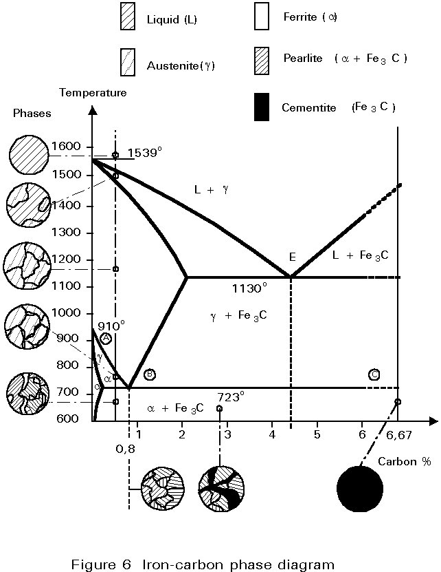
The iron-iron carbide (Fe-Fe3C) phase diagram Microstructures of iron α- ferrite austenite. 2 Interstitial sites of FCC Interstitial sites of BCC. 3 Microstructure in iron-carbon alloys REutectic--pearlite Hypoeutectoid alloys. 4 Hypereutectoid alloys Equilibrium diagrams having intermediate phases or compounds
Coloring Vector Ironcarbon Phase Diagram Stock Vector Royalty Free 1516732415
The Iron-carbon phase or equilibrium diagram is an overall study of iron, carbon, and their alloys and how they act under the various equilibrium conditions. In this blog, we studied these aspects of the equilibrium diagram and also how phase transformation depends upon the temperature conditions.
Solved In The Iron Iron Carbide Phase Diagram Of Figure 6 4 Identify The 1 Answer Transtutors
The iron-iron carbide phase diagram (Fig. ) furnishes a map showing the ranges of compositions. and temperatures in which the various phases such as austenite, ferrite, and cementite are present in. slowly cooled steels. The diagram covers the temperature range from 60O0C to the melting point of.

Can Someone Explain Me About This Iron Carbon Phase Diagram Which Is Beyond 6 67 Wt C Askmemetallurgy
Check Pages 1 - 7 of The iron-iron carbide (Fe-Fe3C) phase diagram in the flip PDF version. The iron-iron carbide (Fe-Fe3C) phase diagram was published by on 2015-05-11. Find more similar flip PDFs like The iron-iron carbide (Fe-Fe3C) phase diagram. Download The iron-iron carbide (Fe-Fe3C) phase diagram PDF for free.
Simple Iron Carbon Diagram
2) Cementite : Iron carbide(Fe 3 C), contains 6.67% wt. C Orthorhombic structure, HARD and BRITTLE 3) Pearlite : Phase mixture (ferrite+cementite), Lamellar structure, contains ~0.8% wt. C Produced from austenite decomposition 4) Austenite : o g-iron, Solid solution, stable at higher temperatures (>727 C) o Max.

Briefly Explain The Eutectic And Eutectoid Reactions In Iron Iron Carbide Fe Fe3c Phase Diagram At What Temperatures And Compositions Percent C Do These Reactions Occur What Are The Phases Before And

Difference Between Steel And Cast Iron Engineering

By Referring To The Iron Iron Carbide Phase Diagram Given Below Answer The Questions That Follow Competens Homeworklib
Cementite
Iron Carbide Ispatguru
1 The Iron Iron Carbide Phase Diagram 17 Download Scientific Diagram

Iron Carbon Phase Or Equilibrium Diagram Or Iron Carbide Diagram Mechstudies Com

Iron Iron Carbide Phase Diagram Example Pdf Heat Treating Manmade Materials

The Iron Iron Carbide Fe Fe C Phase Diagram
Simple
1

Metallurgical Engineering Iron Iron Carbide Phase Diagram Iron Forms Iron Can Exist In Three Forms A Bcc Crystal With Crystal Dimension A 2 86 Angstrom Exists At Temperatures Up To 910oc

The Iron Carbon Phase Diagram
Iron Carbon Phases Metallurgy For Dummies
Practical Maintenance Blog Archive The Iron Iron Carbide Equilibrium Diagram

File Iron Carbon Phase Diagram Svg Wikipedia

The Iron Carbon Equilibrium Diagram Total Materia Article

1 The Iron Iron Carbide Phase Diagram Adapted From Binary Alloy Phase Download Scientific Diagram

Iron Ironcarbide Phase Diagram Pdf Cast Iron Iron

Iron Iron Carbide Phase Diagram
Iron Carbon Phase Diagram Explained With Graphs
Iron Phase Diagram Roy Mech
Solved 12 Refer To The Iron Carbide Phase Diagram Shown Chegg Com

Metastable Iron Carbon Fe C Phase Diagram Diagram Iron Steel Metal Working

Iron Carbide Fe3c An Overview Sciencedirect Topics
Iron Carbon Phase Diagram Steel Cementite Png 1000x714px Phase Diagram Area Austenite Carbon Carbon Steel Download
0 Response to "41 iron iron carbide phase diagram"
Post a Comment