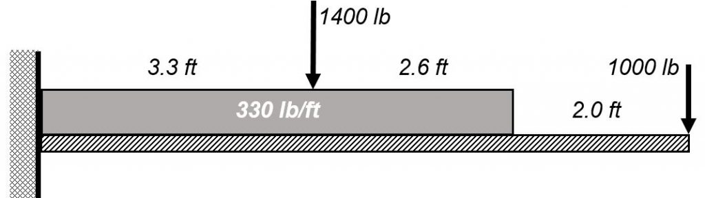
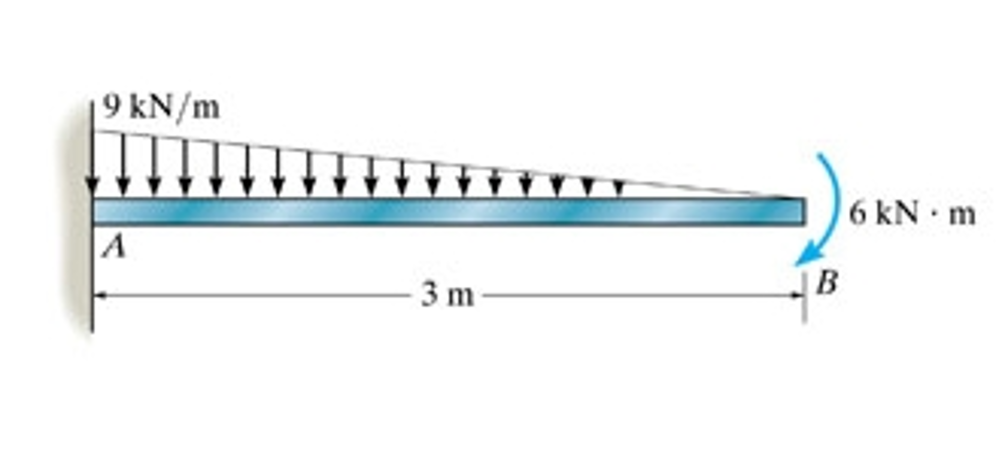
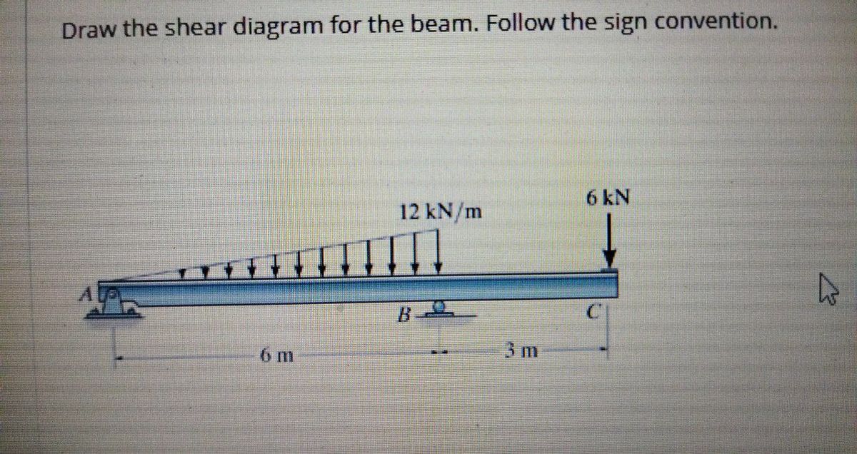
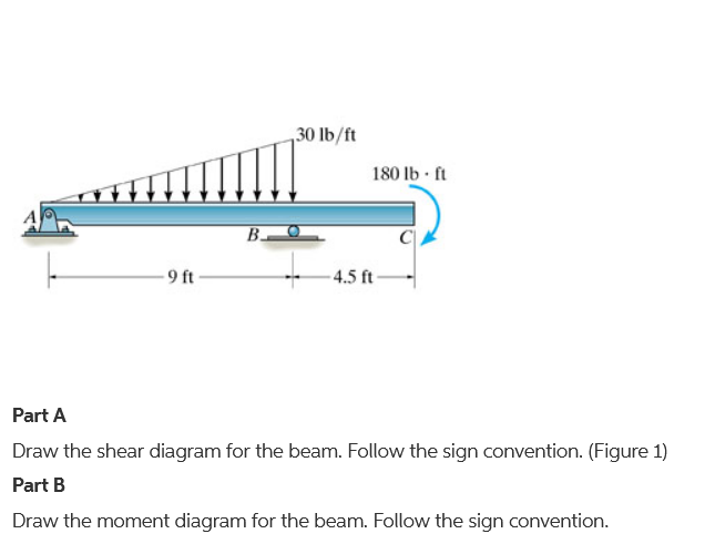
38 draw the shear diagram for the beam. follow the sign convention
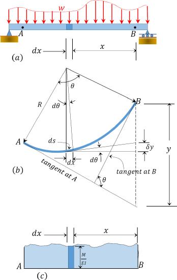
4.0 Building Shear and Moment Diagrams. In the last section we worked out how to evaluate the internal shear force and bending moment at a discrete location using imaginary cuts. But to draw a shear force and bending moment diagram, we need to know how these values change across the structure. The deformation behavior of semi-crystalline polymers is strongly dependent on the morphology formed during processing. In this study, in-situ synchrotron X-ray was firstly used to identify the morphological distributions of injection-molded isotactic polypropylene (iPP) with different concentrations of β-nucleating agent. It was found that under relatively high concentration of β-nucleating ...
Recent Engineering Homework Answers & Textbook Solutions. 1. How can the polarity of an electromagnet be determined if the direction of current flow is known? 2. Define the following terms: Flux density Permeability Reluctance Saturation Coercive force...
Draw the shear diagram for the beam. follow the sign convention
Then draw the shear force diagram sfd and bending moment diagram bmd. For drawing a bending moment diagram or bmd we use a positive sign for the sagging bending moment and a negative sign for the hogging bending moment as shown in the figure below. Follow the sign convention. B if p 20 kn and l 6 m draw the sfd and bmd for the beam. Protein phosphorylation is commonly involved with all of the following except (A) activation of receptor tyrosine kinases. ... Problem 7.75 Draw the shear diagram for the beam. Draw the moment diagram for the beam. 3 m V.N 250 N/m 2 m 500 N 2 m. Nov 11, 2021 ... Answer to Solved - Draw the shear diagram for the beam. Follow the. ... Follow the sign convention. - Draw the moment diagram for the beam. Follow the sign ...
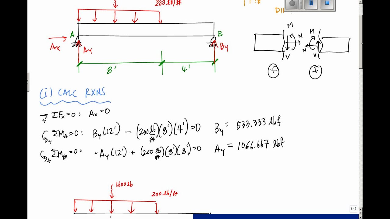
Draw the shear diagram for the beam. follow the sign convention. Once you have the reactions, draw your Free Body Diagram and Shear Force Diagram underneath the beam. Finally calculating the moments can be done in the following steps: 2. From left to right, make "cuts" before and after each reaction/load. To calculate the bending moment of a beam, we must work in the same way we did for the Shear Force ... Using the slope-deflection method, determine the end moments of the beam shown in Figure 11.9a.Assume support B settles 1.5 in, and draw the shear force and the bending moment diagrams. The modulus of elasticity and the moment of inertia of the beam are 29,000 ksi and 8000 in 4, respectively.. Fig. 11.9. Calculating Shear Force Diagram - Step 2: Keep moving across the beam, stopping at every load that acts on the beam. When you get to a load, add to the Shear Force Diagram by the amount of the force. In this case we have come to a negative 20kN force, so we will minus 20kN from the existing 10kN. i.e. 10kN - 20kN = -10kN. Problem 7.59 Part A Draw the shear diagram for the beam. Follow the sign convention.(Figure 1) Part B Draw the moment diagram for the beam. Follow the signconvention. Nov 11, 2021. Problem 6.66 Consider the frame shown in (Figure 1) . Suppose that F 1 = 15 kN . Part A Determine the x and y components of reaction at pin A using scalar notation.
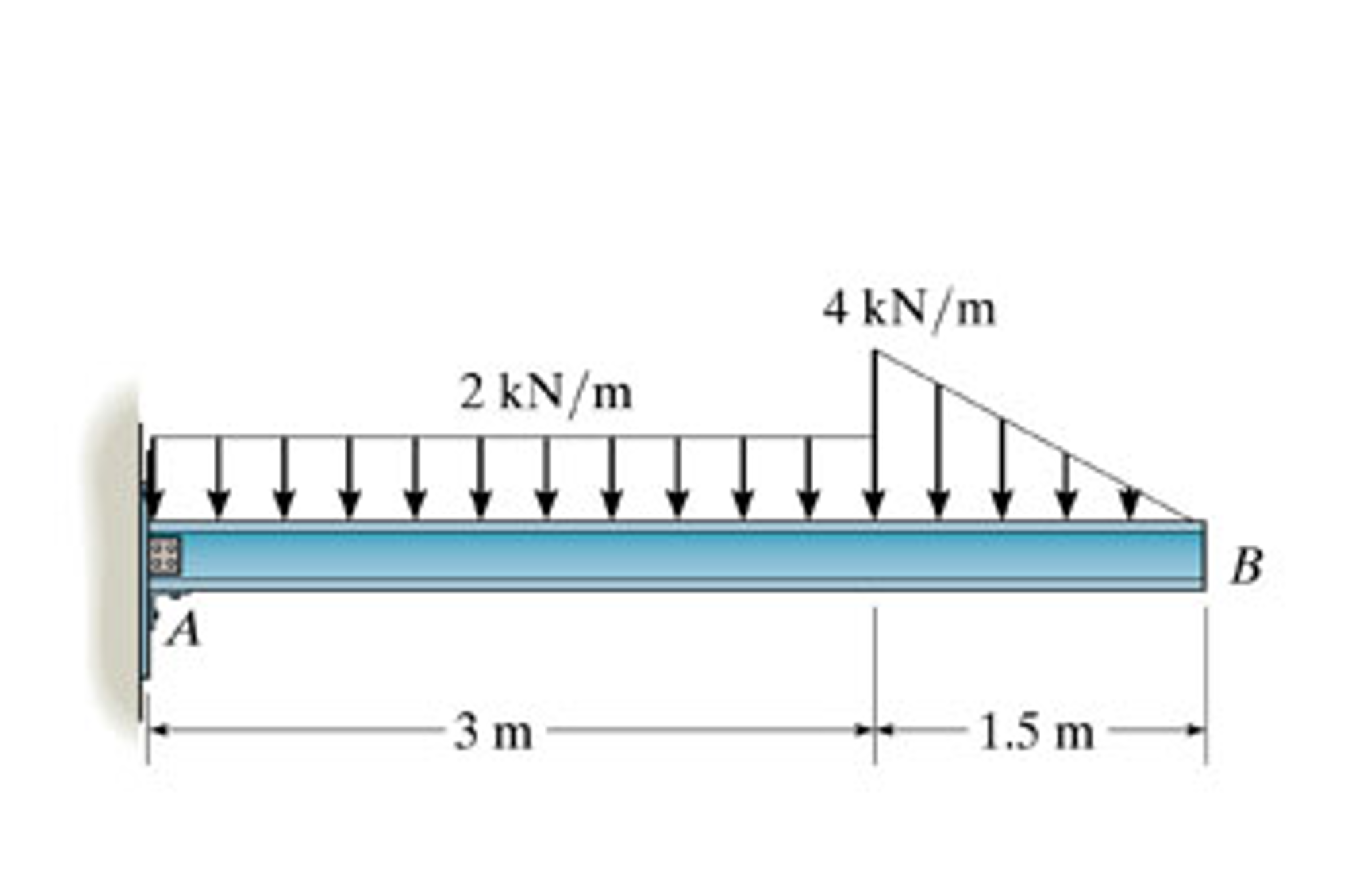
Follow the sign convention. This problem has been solved! See the answer ... Part B Draw the moment diagram for the beam. Follow the sign convention. This problem has been solved! See the answer ... Draw the shear diagram for the beam. Follow the sign convention. You may also like. Category Chegg ... Published on 10 days ago 1 min read. Category Chegg Answers, PHYSICS. Draw a ray diagram for the following situation involving a converging lens. The ray tracing needs to have the three principal rays. ... Draw a structural formula for the ... \ A.Draw the shear diagram for the beam. Follow the sign convention. B. Draw the moment diagram for the beam. Follow the sign convention. 2 kN/m 3 m 4 kN/m 1.5 m. Nov 11, 2021. A distillation column is a process unit in which a feed mixture is separated by multiple partial vaporizations and condensations to form two or more product streams. The ...
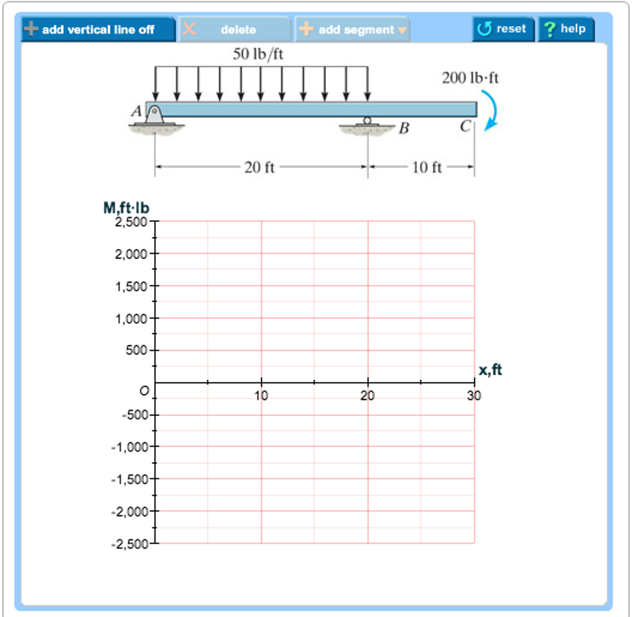
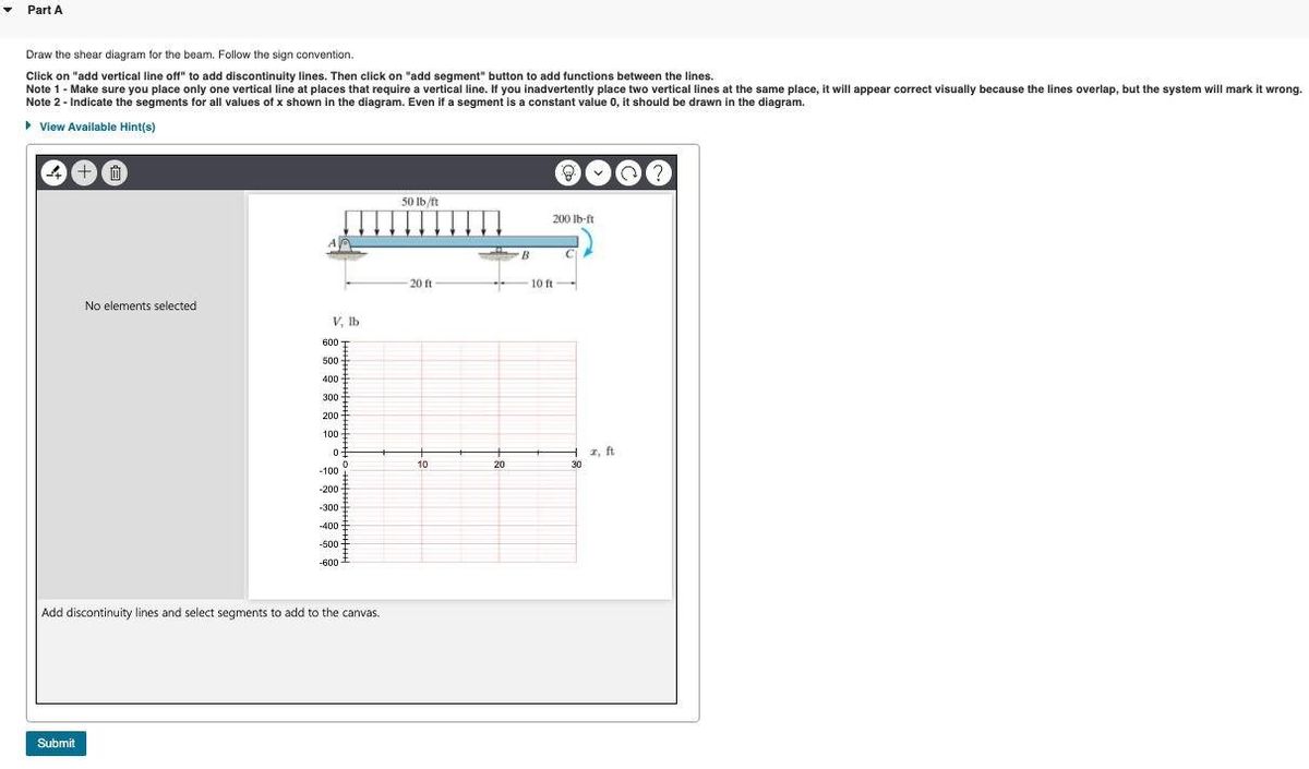
(Figure 1) Part B Draw the moment diagram for the beam. Follow the sign convention. This problem has been solved! See the answer ... Transcribed image text: Problem 7.59 Part A Draw the shear diagram for the beam. Follow the sign convention. (Figure 1) Click on "add vertical line off" to ... View Screen Shot 2021-10-17 at 7.11.03 PM.png from MATH CALCULUS at Lebanon Trail High School. V PartB Draw the bending-moment diagram for the beam. Click on "add vertical line off" to add Fig. P9.1. Simply supported beam. 9.2 Draw the influence lines for the reaction at A and B and the shear and the bending moment at point C of the beam with overhanging ends, as shown in Figure P9.2. Fig. P9.2. Beam with overhang. 9.3 Draw the influence line for the reactions at the support of the cantilever beam shown in Figure P9.3. Fig. P9.3.
Part B Draw the moment diagram for the beam. Follow the sign convention. This problem has been solved! See the answer ...
(Figure 1) Part B Draw the moment diagram for the beam. Follow the sign convention. This problem has been solved! See the answer ...
11/19/21, 5:02 PM Homework_Ch4_1 7/36 Correct Part E Draw the shear diagram for the member . Follow the sign convention for the internal loadings in the member shown in the figure below. Click on "add vertical line off" to add discontinuity lines. Then click on "add segment" button to add functions between the lines.
Draw the shear diagram for the beam. Follow the sign convention. (Figure 1) Draw the moment diagram for the beam. Follow the sign convention. 2 m. 15 kN 200 kN m 1 m. 1 m 10 kN/m 2 m
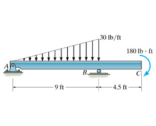
1 Answer to Draw the shear force and moment diagrams for the beam The supports at A and B are a thrust bearing and journal bearing, respectively. (Figure 1) Follow the sign convention.
A beam is shown in the figure below. Figure 1 select the correct shear diagram for the beam. Note make sure you place only one vertical line at places that require a vertical line. Draw the shear diagram for the beam. Follow the sign convention. For The Beam And Loading Shown A Select Correct Shear Bending Moment Diagram s B
Draw the shear diagram for the beam. Follow the sign convention. Next. ... Draw the organic product(s) of the following reaction. Published on 25 days ago 3 min read. Category Chegg Answers, PHYSICS. ... Draw a ray diagram for the following situation involving a converging lens. The ray tracing needs to have the three principal rays.
Classify the beams shown in Figure 3.1 through Figure 3.5 as stable, determinate, or indeterminate, and state the degree of indeterminacy where necessary.. Fig. 3.1. Beam. Solution. First, draw the free-body diagram of each beam. To determine the classification, apply equation 3.3 or equation 3.4.. Using equation 3.3, r = 7, m = 2, c = 0, j = 3. Applying the equation leads to 3(2) + 7 > 3(3 ...
B) Draw the moment diagram for the beam. Follow the sign convention. Show transcribed image text. Expert Answer.
The following three images show how you can temporarily disable the ransomware feature on Avast, which will allow the IOLab software to run. Students have reported that if the above approach didn't work they tried uninstalling and reinstalling Avast. After doing this they ran IOLab again and this time a pop-up appeared asking if they wanted ...
1.5: Internal Forces in Plane Trusses. A truss is a structure composed of straight, slender members connected at their ends by frictionless pins or hinges. A truss can be categorized as simple, compound, or complex. A simple truss is one constructed by first arranging three slender members to form a base triangular cell.
Civil Engineering questions and answers. Draw the shear diagram for the beam Assume that M = 200 Ib. middot ft, and L = 20 ft. Begin by placing the lines of discontinuity. Place the appropriate function between the lines of discontinuity, ensuring the endpoints have the correct values.
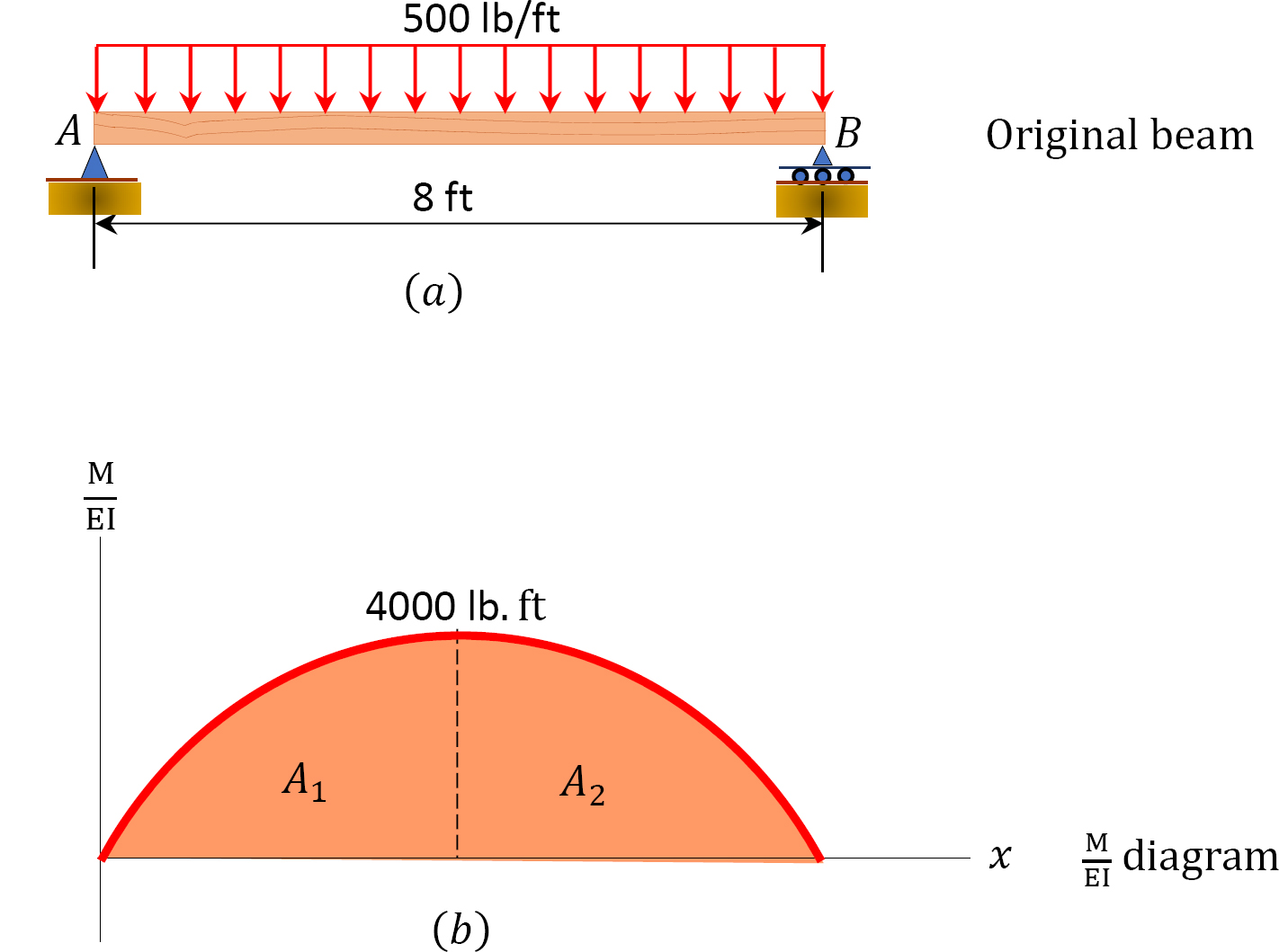
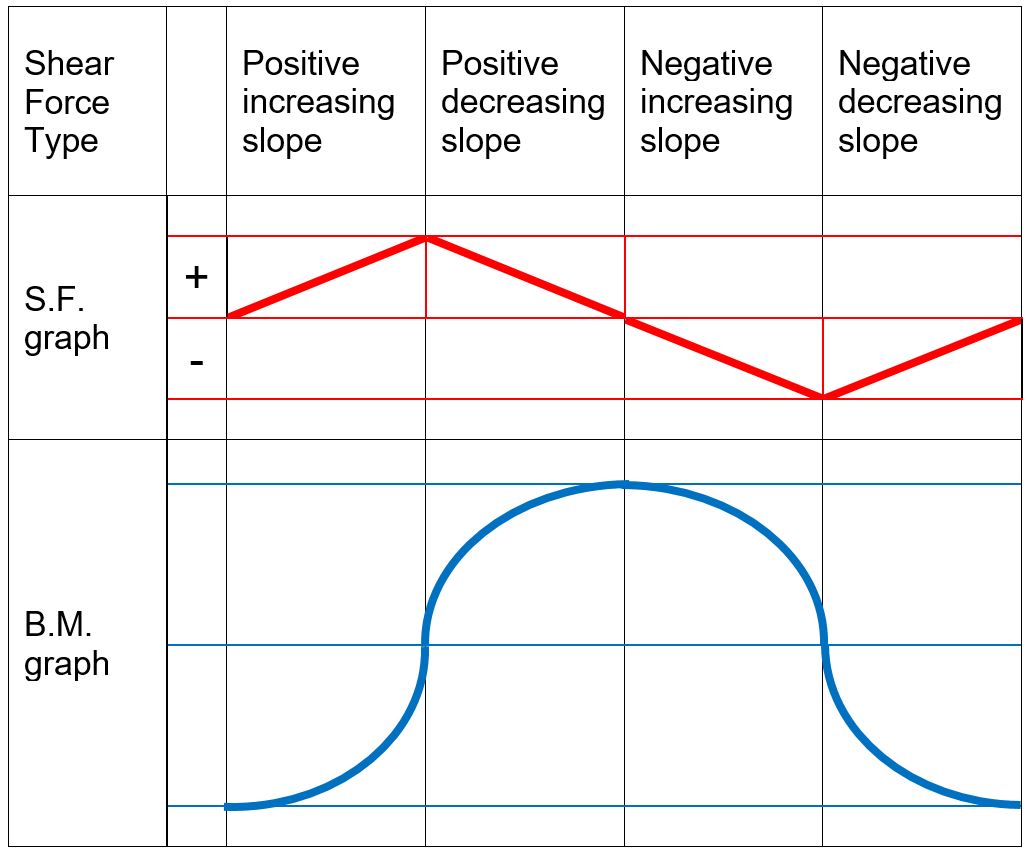
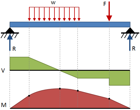
A diagram showing the variation of the shear force along a beam is called the shear force diagram. Bending moment: The bending moment at a section of a beam can be determined by summing up the moment of all the forces acting on either side of the section. The sign convention for bending moments is shown below.
Under the beam, draw your Free Body Diagram and Shear Force Diagram. 2. From left to right, make "cuts" before and after each reaction/load. To calculate the bending moment, follow the same steps we used to calculate the shear force diagram: start at x = 0 and move across the beam, calculating the bending moment at each point.

Draw the shear and moment diagrams for the. beam. Indicate values at the supports and at the points ... In this text, however, we will use the opposite sign convention. and alwa ys draw the moment diagram positive on the compression side of. the member. T his convention follows that used for beams discussed in. Sec. 4-1. T he following ...
Question: Part A. Draw the shear diagram for the beam. Follow the sign convention. (Figure 1) Part B. Draw the moment diagram for the beam. Follow the sign convention.

Draw the shear diagram for the beam. Follow the sign convention. (Figure 1) Click on "add vertical line off" to add discontinuity lines. Then click on "add segment" button to add functions between the lines. Note 1 - The curve you choose from the drop-down is only a pictorial representation of a real quadratic/cubic curve.
Free online beam calculator for generating the reactions calculating the deflection of a steel or wood beam drawing the shear and moment diagrams for the beam. Draw the shear diagram for the beam . The diagram which represents the different effective force on the beam is known as shear and moment diagrams. As shown in figure.
Draw the moment diagram for the beam. Follow the sign convention. This problem has been solved! See the answer ...
Draw the moment diagram for the beam. Follow the sign convention. (Figure 1)Click on "add vertical line off" to add discontinuity lines. Then click on "add segment" button to add functions between the lines. Note 1 - You should not draw an "extra" discontinuity line at the point where the curve passes the x-axis.
Answer to Solved - Draw the shear diagram for the beam. Follow the. ... Follow the sign convention. - Draw the moment diagram for the beam. Follow the sign ...

Protein phosphorylation is commonly involved with all of the following except (A) activation of receptor tyrosine kinases. ... Problem 7.75 Draw the shear diagram for the beam. Draw the moment diagram for the beam. 3 m V.N 250 N/m 2 m 500 N 2 m. Nov 11, 2021 ...

Then draw the shear force diagram sfd and bending moment diagram bmd. For drawing a bending moment diagram or bmd we use a positive sign for the sagging bending moment and a negative sign for the hogging bending moment as shown in the figure below. Follow the sign convention. B if p 20 kn and l 6 m draw the sfd and bmd for the beam.


0 Response to "38 draw the shear diagram for the beam. follow the sign convention"
Post a Comment