38 stinger capacitor wiring diagram
Stinger Wire - Stinger Electronics Power and speaker wire for your high performance car audio installation. CONSTRUCTED FROM PURE 100% VIRGIN COPPER Stinger's power and speaker wire is made of True-Spec, tinned, oxygen-free copper for oxidation prevention, making Stinger one of the best conductors. How to Install H-A-S Rotary Phase Conversion System If the voltage dips below these values, check wire size and transformer KVA. Check appropriate wiring diagram for improper connections. Single Phase L1 & L2 must be connected to Rotary L1 & L2. Check inside rotary panel for signs of defective capacitors. If a capacitor has a bulged case, it is defective and should be replaced.
Stinger 80 Amp Dual Battery Isolator / Relay - Stinger ... The Stinger SGP38 includes. Stinger SGP Series 80 Amp Relay. Mounting Bracket. Instruction Manual. Compatibility Notes. 80 Amp constant current. 150 Amp Peak current. Water resistant black phenolic plastic. Compatible with all types of charging and alternator systems.

Stinger capacitor wiring diagram
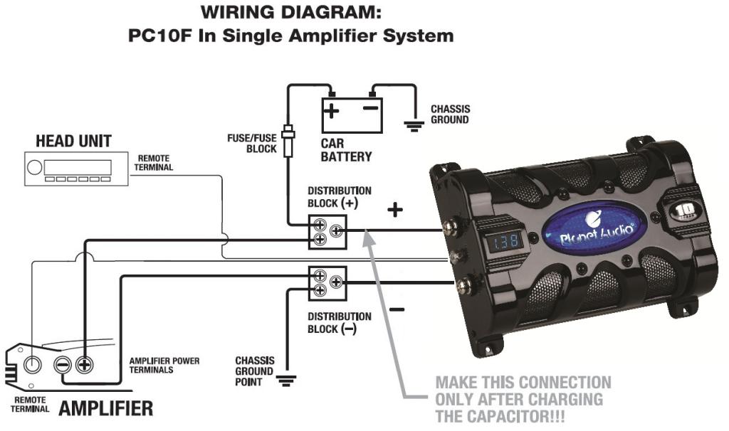
Power Wire - Stinger Electronics Stinger's power wire is made of True-Spec, tinned, oxygen-free copper for oxidation prevention, making Stinger one of the best conductors available. Our wire boasts Hyper-Twist construction, creating a dense yet incredibly flexible wire that's easy to install & provides outstanding performance Car Audio Capacitor Installation A diagram for the capacitor charging setup is shown below. You will need to place a voltmeter across the capacitor to monitor the voltage. Once the voltmeter reads 12 volts (or close to it) you can remove the voltmeter and replace the resistor with the power fuse. Alternatively you can measure the voltage across the charging resistor. Stinger® offers everything you need. PLEASE REFER TO THE INSTRUCTIONS CONTAINED IN THIS. MANUAL FOR CORRECT MOUNTING, CHARGING/DISCHARGING. AND WIRING CONNECTION FOR THIS PRIOR TO INSTALLATION.3 pages
Stinger capacitor wiring diagram. How to Install a Capacitor (with Pictures) - wikiHow Connect the capacitor's negative terminal. This terminal needs to be connected to ground. 6 Connect the remote turn on wire. If your capacitor has an internal meter, it will also have a third wire. This is the remote turn on wire and serves to kill power to the meter whenever the car is turned off. Multiple Capacitor Wiring Diagram Multiple small capacitance capacitors linked to provide the lowest inner. E.S.R. and largest moment discharge power. Multiple Capacitor Wiring Diagram:.2 pages ☑ How To Install A Amp Capacitor Rockford Fosgate Amp Capacitor Kiket 12 Radio Amplifier Capacitor And Cables Ready To Install ... Diagram for Wiring 1 Capacitor to 2 Amps? - the12volt.com One goes to 12v in for the CAP and the other wire from DISTRIBUTION BLOCK goes to the SUB AMP. Disagree. Place the cap in parallel with the subs amp, directly before it, but grounds are separate as talked about above. The distro should be placed before the cap, and its job is to separate sub wire and mains wire.
Installation Assistance - Stinger Electronics Stinger Electronics We design and engineer technology that makes your drive more fun. Built for audiophiles by audiophiles our products span infotainment and radio upgrades, audio upgrades and all the installation accessories to make those enhancements easy. How to Charge a Capacitor - HiFiSoundconnection To add the cap to this system we are going to need are some 4 gauge ring terminals, and additional power wire and ground wire. (Step 1) First to start we remove the fuse up at the fuse holder near the battery. From there we can safely disconnect the main power wire connection at the amplifier Magnatone Lyric, early model, schematic diagram. : The ... The first diagram was for my Magnatone D-8 Lyric, but it's the 2 pickup on each neck model G-85-DW. When I bought it, I knew I would have to replace the TONE pot, as the stem/shaft of the pot was broken off. I carefully made this diagram, to make sure I properly connected the wires to the correct terminals. Thanks. That helps a lot. PDF 4 Wire Limit Switch Circuit Diagram 4-wire-limit-switch-circuit-diagram 1/1 Downloaded from riot.wikiedu.org on April 5, 2022 by guest 4 Wire Limit Switch Circuit Diagram If you ally dependence such a referred 4 Wire Limit Switch Circuit Diagram books that will have the funds for you worth, acquire the utterly best seller from us currently from several preferred authors.
stinger capacitor wiring diagram - Wiring Diagram Stinger Spc5010 Digital Hybrid Capacitor 10 Farads User Manual Manualzz. Multiple Capacitor Wiring Diagram Warning Limited Manualzz. Boss Cprd2 2 Farad Capacitor With Digital Display Black Finish. How The Stinger Vip Components All Wire Together Vortex Radar. Stinger Capacitor Wiring Diagram For Your Needs Stinger Capacitor Wiring Diagram For Your Needs. Electrical cabling is actually a potentially hazardous task if completed improperly. One ought to never attempt working on electrical electrical wiring without knowing the below tips as well as tricks followed by even the most experienced electrician. Stinger Capacitor Wiring Diagram ☑ Amplifier And Capacitor Wiring Details About Stinger True 0 Gauge Amp Kit With 5 Farad Capacitor 1500 Watts Car Audio Kit Set ... How To Charge A Capacitor - Sonic Electronix Learning ... Step 2) Wire up your capacitor by following all the instructions in the installation manual or refer to our " How to Install Car Audio Capacitors " knowledge base. Make sure the power, ground and if applicable the remote turn on wire of the capacitor is connected. Step 3) To begin charging the capacitor you need either a test light or a resistor.
Tezla Audio TZ2100.1 Professional Series Mono Class D Amplifier, 2100 Watts | eBay
The 11 Best Rockford Fosgate 1 Farad Digital Capacitors ... Best For Stereo: Stinger Rockfordfosgate 1 Farad Digital Capacitor . Buy on Amazon. The Stinger Rockfordfosgate 1 Farad Digital Capacitor should be able to handle its purpose and duties with ease. performs similar to a capacitor/battery combo. In addition, the capacitor can be bought for good value and has a great design.
PAC LC-2 2 - Channel Line output converter with Volume control
Scosche 500k Micro Farad Capacitor Wiring Diagram Scosche 500k Micro Farad Capacitor Wiring Diagram A: The rule of thumb is to put in 1 Farad of capacitance for every 1, watts RMS Wiring the bulb or resister across the cap's terminals allows the capacitor to. This is a DC power reservoir for a car audio setup.

11 ideas de Anthony | audio de automóviles, audio coche ...
Coachman amara 380/2 wiring diagram how to fit stinger 310 ... Coachman amara 380/2 wiring diagram how to fit stinger 310 alarm. Posted by Anonymous on Nov 18, 2013. ... Snap a 2 piece ferrite around each wire that comes out of the module and also add a .0.01 or 0.001 capacitor to ground from the higher potential wire connections at each switch you can locate to quench or bleed off the RF. You may need to ...

Stinger Car Audio Capacitors for sale | eBay
Installation Instructions and Owner's Manual for All Stinger ... Refer to the instructions contained in this manual for correct mount- ing, charging/discharging and wiring connection for this capacitor prior to installation.5 pages

10 Farad Capacitor Stinger Digital Led Volt Meter 2000 Watts ...
Best Amp Wiring Diagram With Capacitor For Motion Sensor ... For car amp wiring diagram with capacitor wiring diagram pos amazon com boss cpbk2 2 0 farad led digital car capacitor cap 4 pkg stinger spc505 5 farad capacitor 0 gauge ga amp wire install stinger true 1500w 1 0 gauge car amp wiring kit 2 farad digital wiring diagram for amp and capacitor wiring diagram pos sub amp wiring diagram wiring ...

How To Charge A Capacitor - Sonic Electronix Learning Center ...
Radio Diagram HELP!! | Veloster Forum After i removed the center facia and the radio, i unfortunately found out that the wiring harness diagram to locate all of the speaker wires was not accurate. does anyone have an accurate diagram for a 2013 base V? please help! Sound System: ... Stinger Pro Capacitor, 1 Farad

X-13 Motor Troubleshooting | York Central Tech Talk
Wiring Kits - Stinger Electronics Available in Power and Complete (power + signal) Kits, Stinger's Wiring kits have all the essentials for a professional installation. Featuring 100% oxygen-free tinned copper for a pure, uninterrupted transfer of power. Tru-spec cables/wires meet or exceed the industry standard of copper required for the gauge size.

Stinger SSCap5M Stinger Select Brushed Aluminum 5 Farad Power Capacitor w/ Digital Display
Perfect Amp Wiring Diagram With Capacitor Honda Civic Pdf Wiring diagram 25v capacitor bank for ocl amplifier circuit. Amp wiring diagram with capacitor. Injunction of two wires is usually indicated by black dot in the intersection of two lines. This article gives electric motor start run capacitor installation wiring instructions for electric motor capacitors designed to start run an electric motor ...
Luxaire HBBA-F036SE capacitor wiring diagram - DoItYourself ...
Stinger Electronics STINGER ELECTRONICS. Stinger has everything a true audiophile, and passionate accessorizer needs to upgrade a vehicle's sound or infotainment system, or upfit your boat, SxS, or car with the latest accessories. Stinger sets the bar for badass sound performance and is the go-to brand for car audio enthusiasts, competitors, and car tuners across ...
Capacitors FAQ — What's a Capacitor and What Does It Do?
PDF 4 Wire Limit Switch Circuit Diagram 4-wire-limit-switch-circuit-diagram 1/2 Downloaded from stats.ijm.org on April 5, 2022 by guest 4 Wire Limit Switch Circuit Diagram This is likewise one of the factors by obtaining the soft documents of this 4 Wire Limit Switch Circuit Diagram by online.
Amplifier Wiring Diagrams: How to Add an Amplifier to Your ...
PDF Abt Electronics power wire speaker wire wiring kits hpm digital capacitors pro digital capacitors capacitors batteries alternators battery terminals terminals fuse holders power distribution amperage & voltage status block fused distribution roadkill viw electronics swingerwear stinger. 13160 56 court clearwater, fl 33760 727-572-9255 stingerelectronics.com

Car Audio Capacitor Diagram Wiring Diagram Collection ...
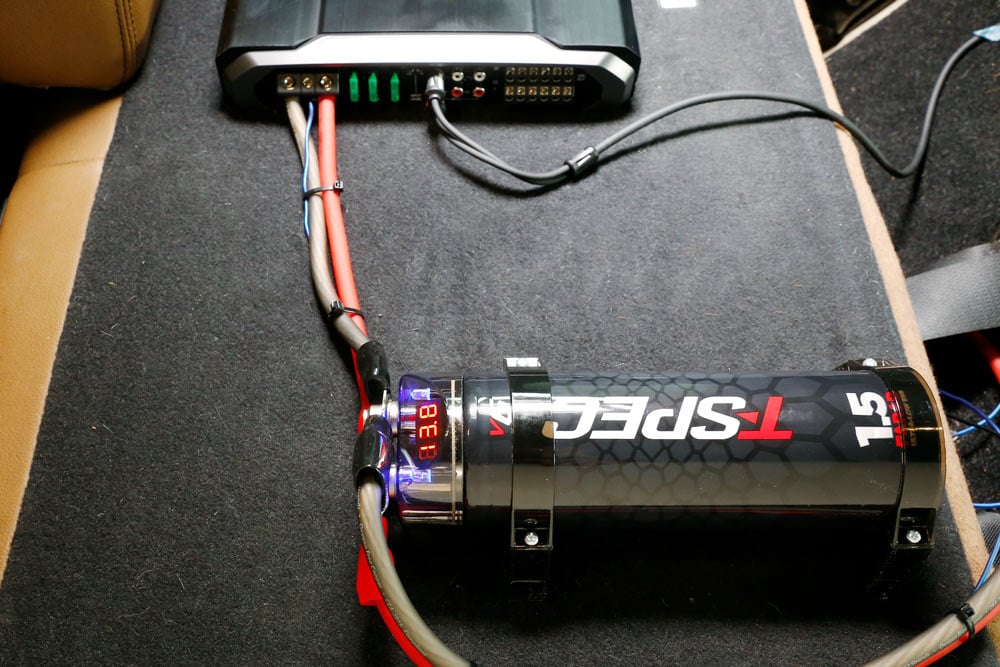
Stinger SPC505 5 Farad Pro Digital Hybrid Capacitor Digital 5 Farad Hybrid Capacitor. 5 farad capacitor for systems up to 1000 Watts. Bright red LED voltage display. performs similar to a capacitor/battery combo. Louder and cleaner bass response. Monitor system voltage. 12-16 volt operation / 18 volt surge. Uses screw terminals for use with 0/4 gauge of power/ground cable.
Planet Audio PC10F 10 Farad Car Capacitor For Energy Storage ...
Stinger® offers everything you need. PLEASE REFER TO THE INSTRUCTIONS CONTAINED IN THIS. MANUAL FOR CORRECT MOUNTING, CHARGING/DISCHARGING. AND WIRING CONNECTION FOR THIS PRIOR TO INSTALLATION.3 pages

New Cbb61 Generator Capacitor 24uf 450vac Brushless Diesel ...
Car Audio Capacitor Installation A diagram for the capacitor charging setup is shown below. You will need to place a voltmeter across the capacitor to monitor the voltage. Once the voltmeter reads 12 volts (or close to it) you can remove the voltmeter and replace the resistor with the power fuse. Alternatively you can measure the voltage across the charging resistor.
DETAILED FEATURES: INSTALLATION AND MOUNTING: CHARGING THE ...
Power Wire - Stinger Electronics Stinger's power wire is made of True-Spec, tinned, oxygen-free copper for oxidation prevention, making Stinger one of the best conductors available. Our wire boasts Hyper-Twist construction, creating a dense yet incredibly flexible wire that's easy to install & provides outstanding performance
Untitled

Battery Eliminator Capacitor — Moped Army
Car Audio Speaker Wiring - The 1947 - Present Chevrolet & GMC ...

Stinger SPC5010 10 Farad Hybrid Capacitor W/ Digital Voltage ...

Stinger Car Amplifier Parts & Accessories for sale | eBay

How to Install Car Audio Capacitors - Sonic Electronix ...

I have red zero's flashing on my scosche 500k capacitor - Fixya

Lea How To... Factory Reset A Caravan Alarm en línea

Multiple Capacitor Wiring Diagram: WARNING!! LIMITED | Manualzz
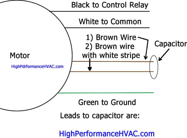
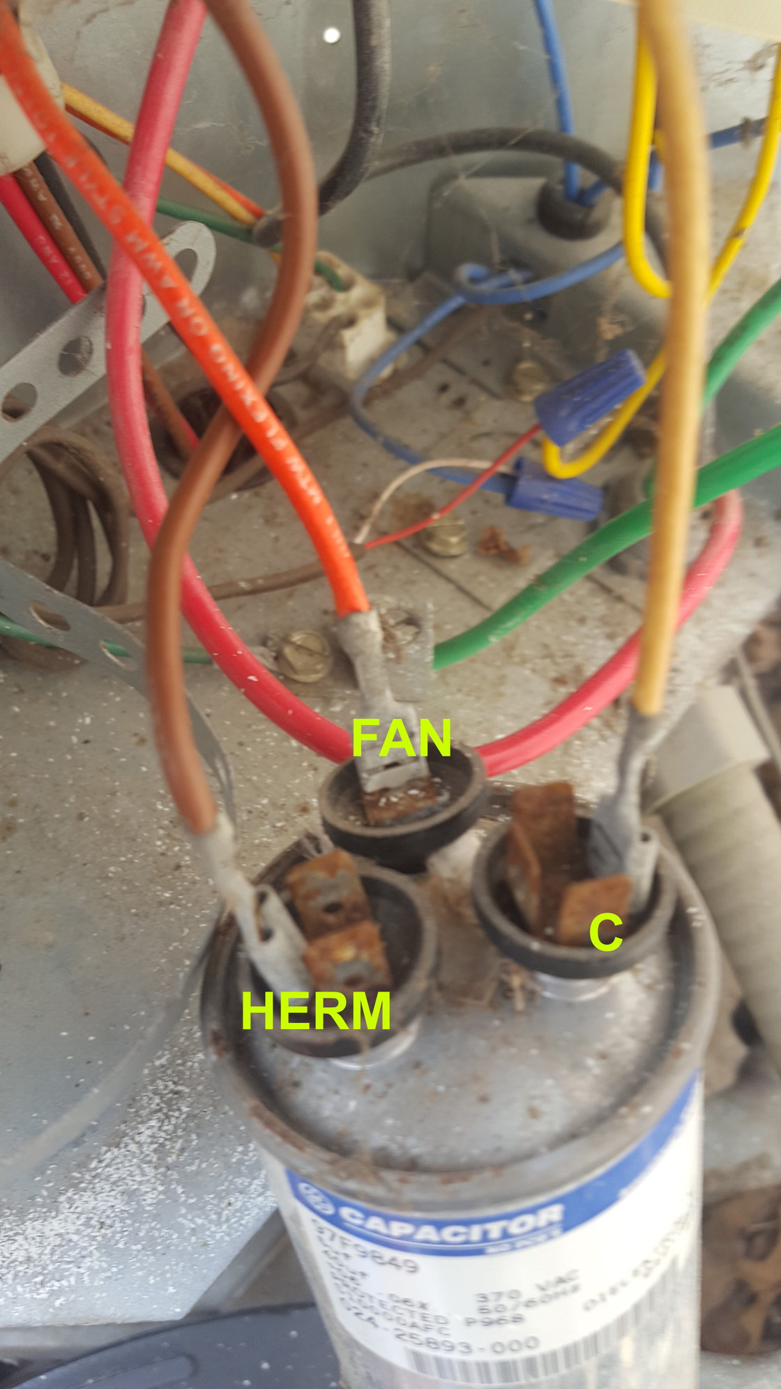
How to Wire a Run Capacitor to a Motor Quality Wiring 101
Installation Instructions and Owner's Manual for All Stinger ...
Installation Instructions and Owner's Manual for All Stinger ...

How to install a car audio capacitor

Car Audio - Car Installation and Accessories - Capacitors and ...

Stinger SPC505 Pro Hybrid 5 Farad Capacitor

HOW TO INSTALL A CAPACITOR WITH AC CAPACITOR WIREING TO YOUR CAR TUTORIAL

CARBON FIBER 2 FARAD DIGITAL CAPACITOR – Stinger Electronics

How To Install Car Audio Power Capacitor To Amp Installation ...
Installation Instructions and Owner's Manual for All Stinger ...

How To Charge and Install a Capacitor | Car Audio Q&A

CARBON FIBER 2 FARAD DIGITAL CAPACITOR – Stinger Electronics

Stinger SSCap5M Stinger Select Brushed Aluminum 5 Farad Power Capacitor w/ Digital Display

How to Wire a Run Capacitor to a Motor Quality Wiring 101
0 Response to "38 stinger capacitor wiring diagram"
Post a Comment