37 allen bradley motor starter wiring diagram
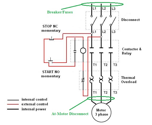
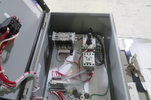
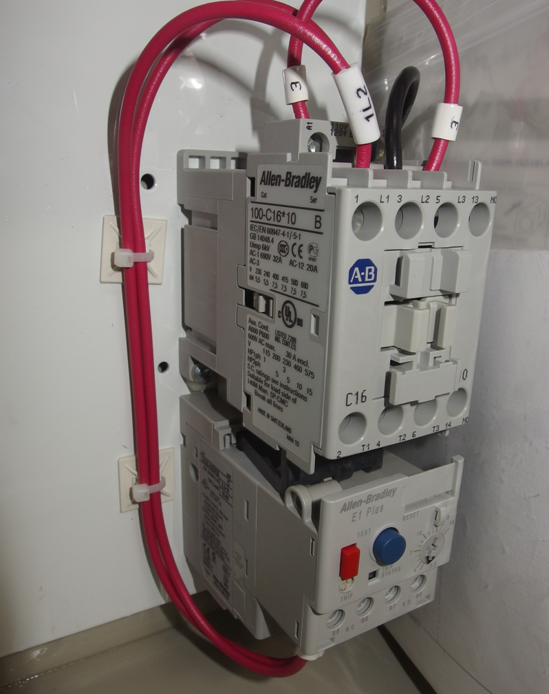
Allen Bradley100-c09*10 Wiring Diagram Allen Bradley100-c09*10 Wiring Diagram Allen Bradley C09 10 Motor Starter Vac Coil 25 Amp 3 Pole. $ . Allen Bradley MN Manual Motor Starter Series D Amp. $ Allen Bradley ACBH1 and CB3G Circuit Breaker 32 Amp. V ~ (ac) IEC contactor (Allen-Bradley C09*10) A detailed wiring diagram is available in Figure 4. Wiring diagram for programmable freezer. Allen Bradley Reversing Motor Starter Wiring Diagram ... Low Voltage Starters Allen Bradley United States 2100 Wd1 Wiring Diagrams Magnetic Starter Wiring An Allen Bradley 709 3 Phase For Single 220v The Hobby Machinist Allen Bradley 705 Cod103 Ser K Nema Size 2 Reversing Motor Starter 25hp 460v 124 95 Picclick
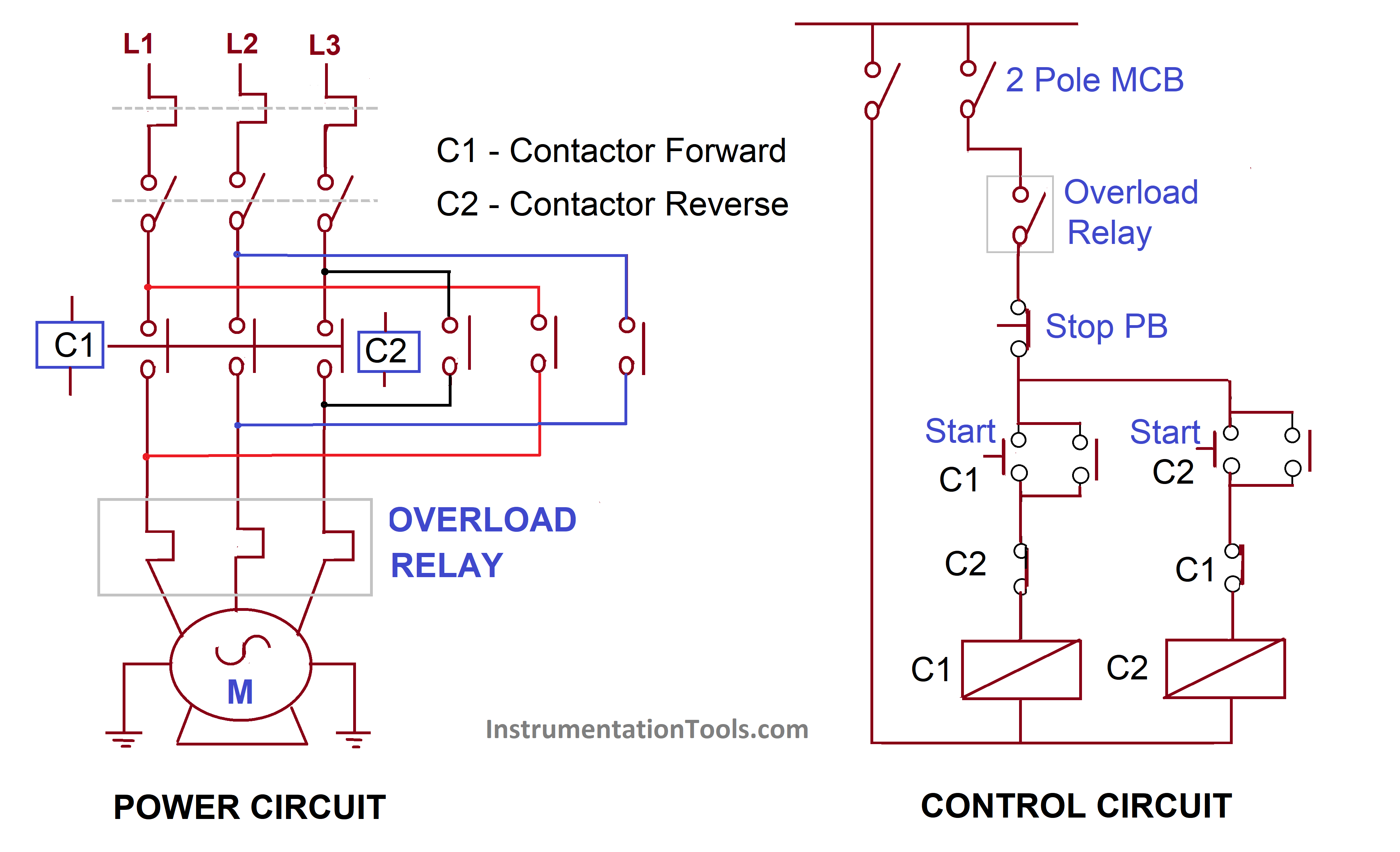
Allen Bradley Reversing Contactor Wiring Diagram The Allen-Bradley Bulletin Definite Purpose contactors are specifically designed for Typical Wiring Diagrams (See Applicable Codes and Laws). 1- SQUARE D - WIRING DIAGRAM BOOK (excerpts). LAB #4 - SEQUENCING AND REVERSING CIRCUITS ALLEN BRADLEY - CENTERLINE - INSTRUCTION MANUAL magnetic contactors and magnetic motor starters.
Allen bradley motor starter wiring diagram
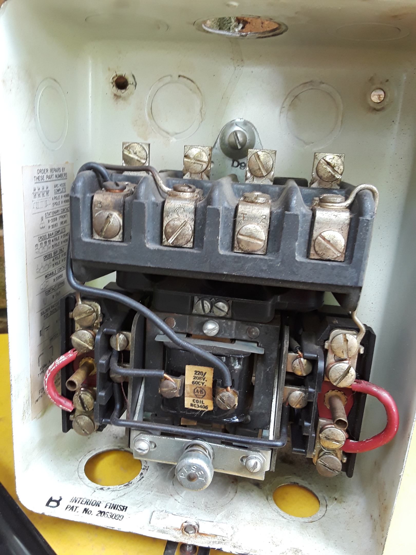
Motor Control | Allen-Bradley United States NEMA Manual Motor Starting Switches are designed for use on motor starting installation. The Bulletin 600 switches offer overload protection for small 1-phase AC/DC motors. The Bulletin 609 and 609U switches are designed for use on motor starter installations where remote push button control is not required. Allen Bradley Motor Starter With Overload Protection ... The examples and diagrams in this manual are included solely for illustrative purposes.. documentation, contact your local Allen-Bradley distributor or Rockwell .. motor control program that is used to reduce motor starter control wiring and You can adjust this parameter in the Overload Protection display and press. some of the useful ways ... Allen Bradley Motor Starter Manual - inspire referances 2022 Allen bradley manual motor starter, 140 mn 0400 brand allen bradley model 140 mn phases manufacturer allen bradley sku 051c this item is used and was once removed from a working environment. Show only products on sale in stock only.
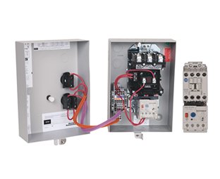
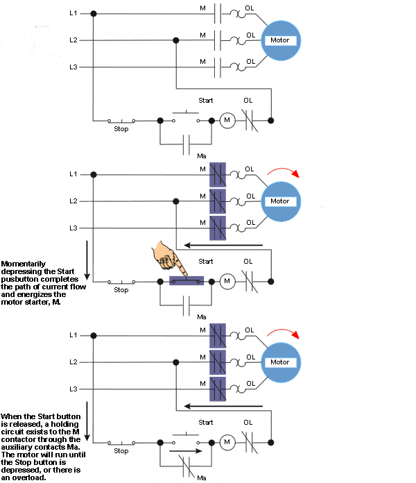
Allen bradley motor starter wiring diagram. IEC Open Starters | Allen-Bradley United States Non-reversing (Bulletin 190S) and reversing (Bulletin 191S) Two components starters with motor protection circuit breaker and choice of miniature or standard contactor. cULus Listed for control and protection of motor loads. Mounting options: snap fixing on (1) or (2) 35 mm top hat rails. IEC Open Starters. Allen bradley motor starter 3 phase wiring diagrams ... Automated solutions that can be tailored to a broad range of industries. 3 phase motor starter wiring diagram pdf sample - 3 phase motor starter circuit diagram best control wiring star. Md is difficult to control ,nil\3 on the gzound. of the propellar and motor system and cause. 3, a a single-phase ac motor connected to a drum switch. Allen Bradley Motor Starter Wiring Diagram - Wiring Diagram Allen bradley motor starter wiring diagram. Allen bradley motor starter wiring diagram fresh fine allen bradley. Dol motor starter with 230v contactor coil. Nema manual motor starting switches are designed for use on motor starting installation. Variety of allen bradley soft starter wiring diagram. You must watch this video. PDF 800-2.0 Typical Wiring Diagrams for Push Button Control ... units, the suggested internal wiring, and connections with the starter. Symbols common to most circuits are explained on Page 5. Less common symbols are explained where they occur. NOTE - The symbols used in this publication were adapted by Allen-Bradley for use in accordance with NEMAby Allen-Bradley for use in accordance with NEMA standards.
PDF NEMA Manual Starting Switch Specifications 609U and 609TU Typical Wiring Diagram (See Applicable Codes and Laws) Coil VA Inrush 14.2VA Sealed 4.6VA Motor Black Red Undervoltage Coil O.L. O.L. O.L. PL Remove Jumper "A" to connect remote stop operator wires to vacated terminals. Note:Jumper not available on devices in Type 7 and 9 Enclosure. Allen Bradley Starter Wiring Diagrams - Wiring Diagram Line Allen Bradley Starter Wiring Diagrams Wiring Diagram Line Uncategorized ... Magnetic starter wiring an allen bradley 709 3 phase for single 220v the hobby machinist démarreurs à pleine tension ouverts fermés nema france vacuum contactor and specifications size 1 with start stop ons 509 bod a2g 90011 non reversing united kingdom iec enclosed ... Allen Bradley Wiring Diagrams Motor Starter - Wiring Diagram allen bradley 709 3 phase starter motor control design automationprimer size 1 with start powerflex vfd voltage starters electrical and electronic drawing nema practical machinist largest iec open denmark wiring contactors for loads guardmaster safety relay doent 10281863 5 combination 512 bab 24 knoware software education industry ancient 2 wire … Allen Bradley Powerflex 70 Wiring Diagram - namabayi.co Allen bradley motor starter wiring diagram. A wiring diagram usually gives recommendation not quite the relative point and concord of. Allen bradley powerflex 70 wiring diagram The powerflex drive has an input which can be wired to a fire control panel or other fire/life. This allen bradley 22 a vfd is a 15 horsepower drive.
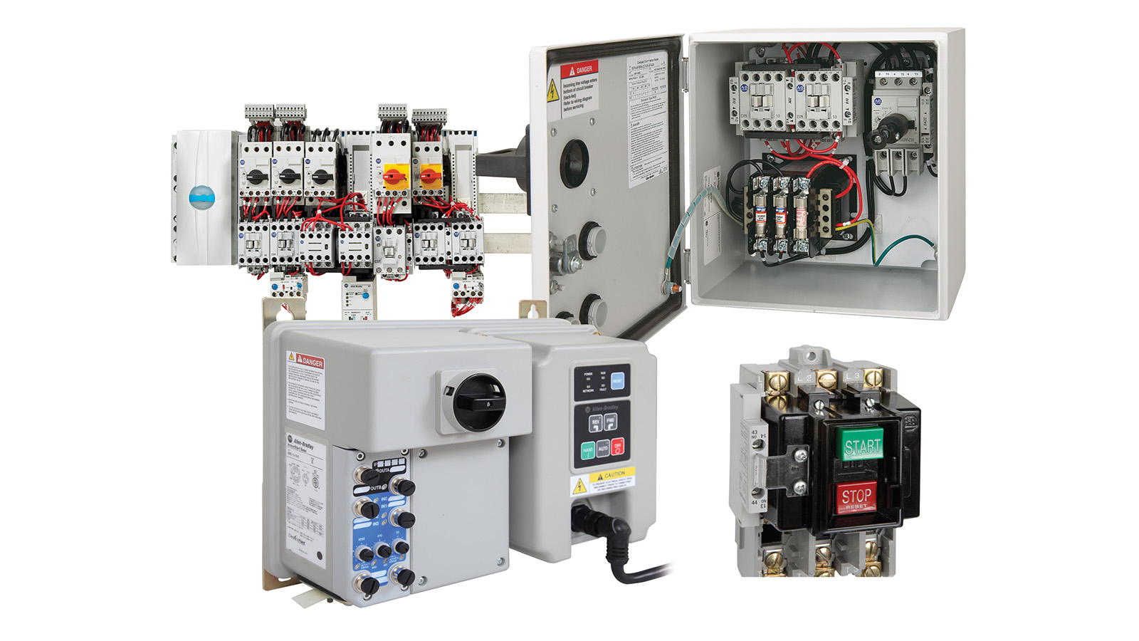
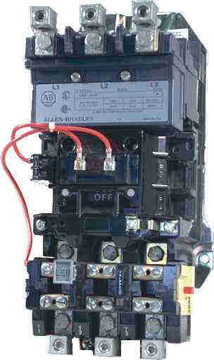
NEMA Open/Enclosed Full Voltage Starters | Allen-Bradley ... NEMA sizes 00…9. Non-combination with NEMA contactor and electronic overload relay with optional communication module. Vertically arranged available with the Bulletin 505V in sizes 0…5. Available with metal enclosure: Type 1, 3R/12, 4/4X stainless steel, and 7 & 9 hazardous location. Bulletin 520 Multi-speed. PDF GI-2.0: Typical Wiring Diagrams - Rockwell Automation Wiring diagrams do not show the operating mechanism since it is not electrically controlled. These motor starters consist of an "ON-OFF" snap switch combined with a thermal overload device operating on the eutectic alloy ratchet principle. Terminal markings corresponding to those shown on the diagrams will be found on each switch. Allen Bradley Motor Starter Manual - inspire referances 2022 Allen bradley manual motor starter, 140 mn 0400 brand allen bradley model 140 mn phases manufacturer allen bradley sku 051c this item is used and was once removed from a working environment. Show only products on sale in stock only. Allen Bradley Motor Starter With Overload Protection ... The examples and diagrams in this manual are included solely for illustrative purposes.. documentation, contact your local Allen-Bradley distributor or Rockwell .. motor control program that is used to reduce motor starter control wiring and You can adjust this parameter in the Overload Protection display and press. some of the useful ways ...
Motor Control | Allen-Bradley United States NEMA Manual Motor Starting Switches are designed for use on motor starting installation. The Bulletin 600 switches offer overload protection for small 1-phase AC/DC motors. The Bulletin 609 and 609U switches are designed for use on motor starter installations where remote push button control is not required.












0 Response to "37 allen bradley motor starter wiring diagram"
Post a Comment