41 derive the state table and state diagram for the sequential circuit
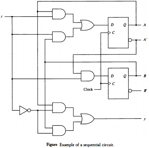
Solved Derive the state table and state diagram of the ... Question: Derive the state table and state diagram of the sequential circuit shown below. Draw a timing diagram for clk, x. A and B for 10 clock cycles, assuming that the machine starts in state 00 and x is always 1. Explain the function that the circuit performs, when the machine starts in state 00 and x is always 1. Solved Q1: Derive the state table and the state diagram of ... Q1: Derive the state table and the state diagram of the sequential circuit shown in Fig. (10+5=15 pts.) CLOCK ; Question: Q1: Derive the state table and the state diagram of the sequential circuit shown in Fig. (10+5=15 pts.) CLOCK
Complete Table Truth For The Circuit The Sequential ... A Sequential Circuit with two D Flip-Flops A and B, one input X, and one output z is specified by the following next state and output equations:A(t+1)=A'+bB(t+1)=B'xz=A+B'A) Draw the logic diagram of the circuitB) List the state table for the circuitC) Draw the corresponding state diagram.
Derive the state table and state diagram for the sequential circuit
PDF Circuits with Flip-Flop = Sequential Circuit Circuit ... Circuit,,g, State Diagram, State Table Circuits with Flip-Flop = Sequential Circuit Circuit = State Diagram = State Table State MinimizationState Minimization Sequential Circuit Design Example: Sequence Detector Examppyle: Binary Counter. Circuit, State Diagram, State Table. Solved 5-8 Derive the state table and the state diagram of ... Refer to the given sequential circuit, the equations for T-flip flops are given by, Using the above equations and assuming the present states( 00,01,10,11… View the full answer Transcribed image text : 5-8 Derive the state table and the state diagram of the sequential shown circuit. Exams/review2015 fsmonehot - HDLBits Derive state transition and output logic equations by inspection assuming a one-hot encoding. Implement only the state transition logic and output logic (the combinational logic portion) for this state machine. (The testbench will test with non-one hot inputs to make sure you're not trying to do something more complicated).
Derive the state table and state diagram for the sequential circuit. Difference between Star and Delta Connections - Comparison Of Y/Δ Below is a given table which compares both Star and delta connections showing the exact difference between Star (Y) and Delta (Δ) Connections. Star Connection: Star connection “Y” is obtained by joining together similar ends of coils either “starting” or finishing. P57 Derive the state table and state diagram of the ... Problems 237 (a) Draw the logic diagram of the circuit. (b) TabuIate the state table. (cj* M v e the state equations for A and B. 5.11* Starting from state 00 in the state diagram of Fig. 5.16, determine the state transitions and output sequence that will be generated when an input sequence of 0101 101 1101 1110 is applied. 5.1s Reduce the ... Answered: Derive the state table and the state… | bartleby Solution for Derive the state table and the state diagram for the sequential circuit shown below. CP. close. Start your trial now! First week only $4.99! arrow_forward ... Derive the state table and the state diagram for the sequential circuit shown below. CP. Question. digital system class. fullscreen Expand. PDF Sequential Circuit Analysis 10 Elec 326 19 Sequential Circuit Analysis Derive the state table from the transition table: Where 00 = A, 01 = B, 10 = C, 11 = D Derive the state diagram from the state table: Q X=0 X=1 AA B0 BB D0 CC A1 DD C1 Q* Z Elec 326 20 Sequential Circuit Analysis 4. Synchronous Sequential Circuits & Verilog Blocking vs. non-blocking assignment statements
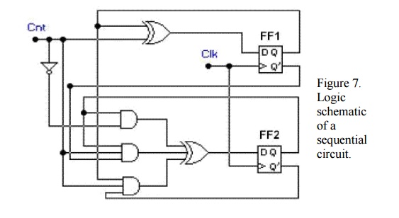
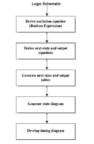
Solved Derive the state table and the state diagram of the ... Derive the state table and the state diagram of the sequential circuit shown in Fig. P6-9. Explain the function that the circuit performs. CP FIGURE P6-9 ; Question: Derive the state table and the state diagram of the sequential circuit shown in Fig. P6-9. Explain the function that the circuit performs. CP FIGURE P6-9 PDF Sequential Circuit and State Machine State Transition ... different output sequence Sequential Circuit and State Machine 2 • Example: - A very simple machine to remember which building I am at - The only input is the clock signal - The state machine is represented as a state transition diagram (or called state diagram) below - One step (i.e., transition) can be taken whenever there is a ... PDF Derive the state table and state diagram for the ... Derive the state table and state diagram for the sequential circuit. Logic schematic of a sequential circuit. SOLUTION: STEP 1: First we derive the Boolean expressions for the inputs of each flip-flops in the schematic, in terms of external input Cnt and the flip-flop outputs Q1 and Q0. Since Chapter 6 Synchronous Sequential Circuits 1. Obtain the specification of the desired circuit. 2. Derive a state diagram. 3. Derive the corresponding state table. 4. Reduce the number of states if possible. 5. Decide on the number of state variables. 6. Choose the type of flip-flops to be used. 7. Derive the logic expressions needed to implement the circuit.
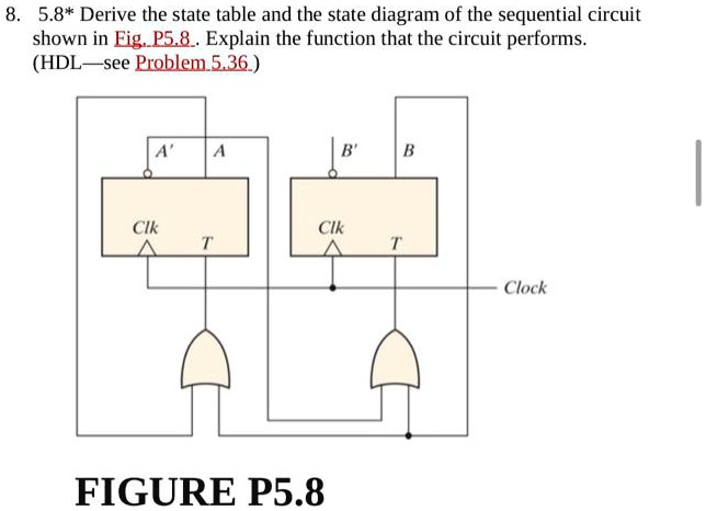
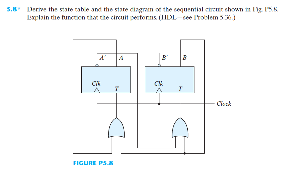
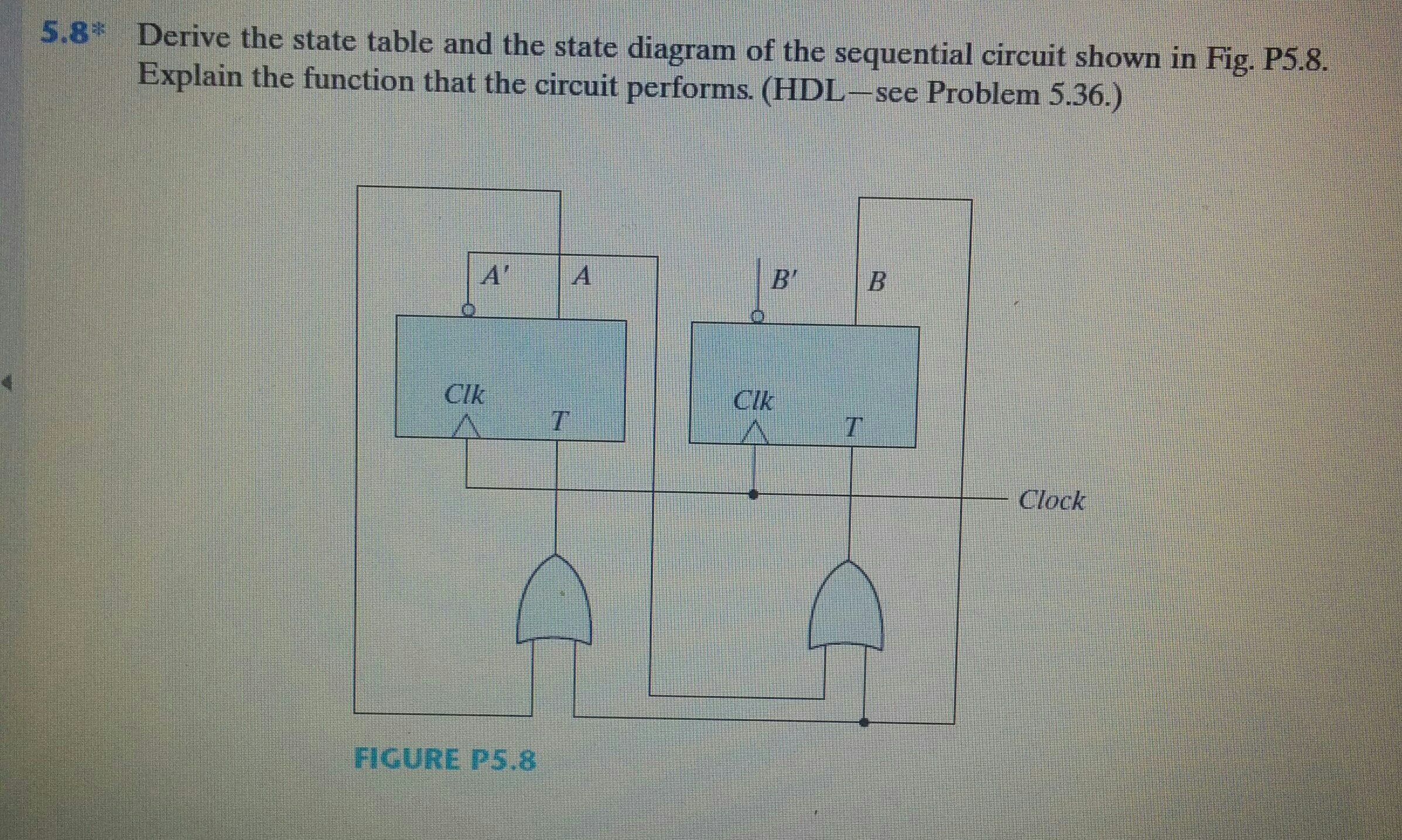
Solved Derive the state table and the state diagram of the ... Derive the state table and the state diagram of the sequential circuit shown in Fig. P5.8. Explain the function that the circuit performs. (HDL see Problem 5.36.) Question: Derive the state table and the state diagram of the sequential circuit shown in Fig. P5.8. Explain the function that the circuit performs. (HDL see Problem 5.36.) Step by Step Method to Design a Combinational Circuit - VLSIFacts Aug 23, 2016 · Understand the problem statement (realize how the outputs of the circuit depend on the inputs to the circuit) Draw the Truth Table (Truth Table establishes the relationship between the outputs and inputs for all the possible input combinations) Derive the minimized Boolean Expressions for the outputs w.r.t. the inputs (You can use the K-Map method) State Diagram and state table with solved problem on state ... The information contained in the state diagram is transformed into a table called a state table or state synthesis table. Although the state diagram describes the behavior of the sequential circuit, in order to implement it in the circuit, it has to be transformed into the tabular form. The below table shows the state table for Mealy state ... PDF Sequential Circuit and State Machine State Transition ... •Combinational circuits - output is simply dependent on the current input • Sequential circuits - output may depend on the input sequence • The effect of the input sequence can be memorized as a state of the system Sequential Circuit and State Machine 1 • So a sequential circuit is also called a State Machine • Memory elements (usually D flop -flips) are used to store the
Solved] Question 1: Design the sequential circuit specified ...
PDF Circuits with Flip-Flop = Sequential Circuit Circuit ... Sequential circuit components: Flip-flop(s) Clock Logic gates Input Output Circuit, State Diagram, State Table
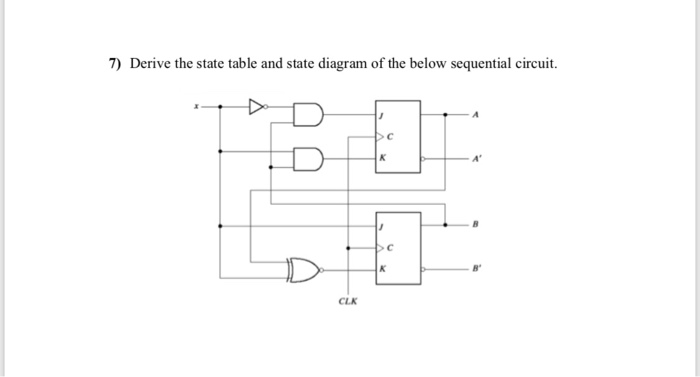
Solved: 7 Derive State Table State Diagram Sequential Circ
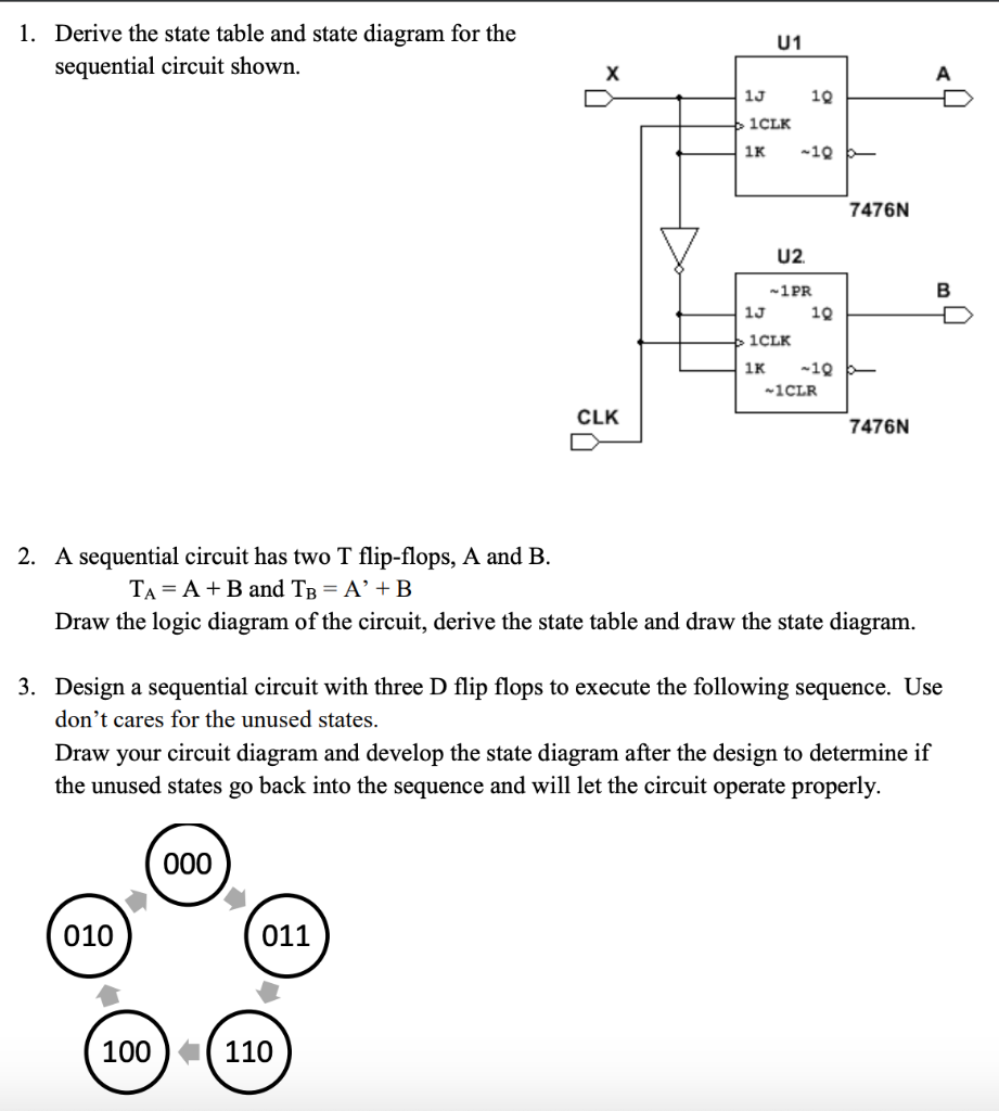
exam 001 (202).pdf - Question: Derive the state table and ... Draw the state diagram by observing present state and next state in table 2. Thus, state table and state diagram has been implemented for the sequential circuit. From Table 2, it is seen that the counter counts and . Therefore, the circuit acts as a mod 2 counter . Here, the state 11 is unused state.
Solved] Part 1 5.8* Derive the state table and the state ...
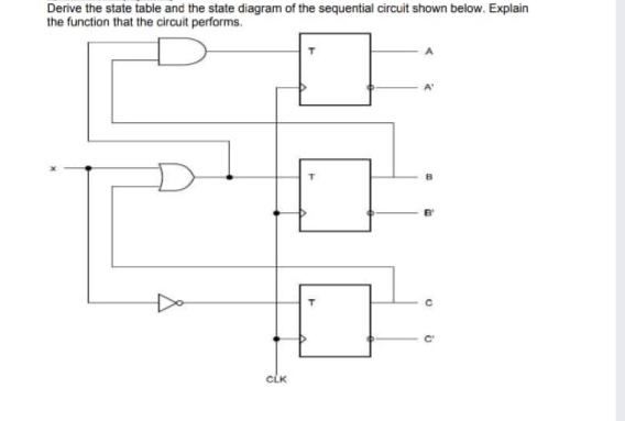
Solved 4. Derive the state table and the state diagram of ... 4. Derive the state table and the state diagram of the sequential circuit shown below. Obtain the output and state sequence with the input sequence: 0110111010. 21 D ) D Q 21 y2 V2: te qe clk 22 ; Question: 4. Derive the state table and the state diagram of the sequential circuit shown below.
Computer Organization and Architecture (Sequential Circuits ...
Analysis and Design of Sequential Circuits - BrainKart The behaviour of a sequential circuit is determined from the inputs, the outputs and the states of its flip-flops. Both the output and the next state are a function of the inputs and the present state. Derive the state table and state diagram for the sequential circuit shown in Figure 7. STEP 1: First we derive the Boolean expressions for the ...
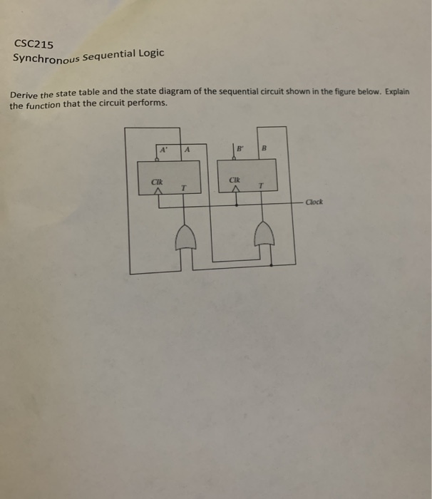
Solved) : Csc215 Synchronous Sequential Logic Derive State ...
Q. 5.8: Derive the state table and the state diagram of ... Q. 5.8: Derive the state table and the state diagram of the sequential circuit shown in Fig. P5.8. Explain the function that the circuit performs.Please subs...
Answered: Derive the state table and the state… | bartleby
Q4c. Analyze the following circuit to derive the | Chegg.com Electrical Engineering questions and answers. Q4c. Analyze the following circuit to derive the state table and the state diagram of the sequential circuit shown below. [12 marks] lgogdogo OG X'OB' 00--004 A J 1 D CLK 1 O х 21 к o O 1 1 1 Ax' B 1 0 12 / CLK 1 1 0 K 14 Clock 1. Question: Q4c.

SOLUTIONS: to Additional: SEQUENTIAL CIRCUITS For Circuit ...
(a) Derive the state graph and table for a Mealy ... (a) Derive the state graph and table for a Mealy sequential circuit which converts a serial stream of bits from NRZ code to NRZI code. Assume that the clock period is the same as the bit time as in Figure 14-20. (b) Repeat (a) for a Moore sequential circuit.
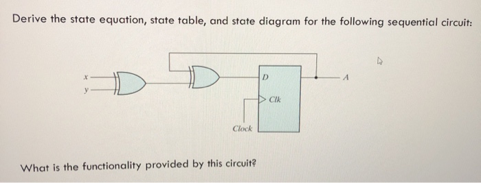
Solved: Derive the state equation, state table, and state
PDF How to derive a state diagram? - KTH It will be easier to reason the way to the state table if state symbols (or state numbers) reflects the "characteristics" of the states. Eg "z . w. 1. w. 0 ". Temporary state numbers. are here derived from output value in states and from the input combination that leads to the state. If you just name the states . a … h . it may be a ...
Analysis and Design of Sequential Circuits
Exams/review2015 fsmonehot - HDLBits Derive state transition and output logic equations by inspection assuming a one-hot encoding. Implement only the state transition logic and output logic (the combinational logic portion) for this state machine. (The testbench will test with non-one hot inputs to make sure you're not trying to do something more complicated).
![Solved] Derive the state table and state diagram of the ...](https://s3.amazonaws.com/si.experts.images/questions/2020/04/5ea2f800b1bb8_1587738621679.jpg)
Solved] Derive the state table and state diagram of the ...
Solved 5-8 Derive the state table and the state diagram of ... Refer to the given sequential circuit, the equations for T-flip flops are given by, Using the above equations and assuming the present states( 00,01,10,11… View the full answer Transcribed image text : 5-8 Derive the state table and the state diagram of the sequential shown circuit.
Solved 1. Derive the state table and state diagram for the ...
PDF Circuits with Flip-Flop = Sequential Circuit Circuit ... Circuit,,g, State Diagram, State Table Circuits with Flip-Flop = Sequential Circuit Circuit = State Diagram = State Table State MinimizationState Minimization Sequential Circuit Design Example: Sequence Detector Examppyle: Binary Counter. Circuit, State Diagram, State Table.
Analysis and Design of Sequential Circuits
SOLVED:5.8* Derive the state table and the state diagram of ...

Example 1.1
Introduction to State Table, State Diagram & State Equation
Solved) - https://www.chegg.com/homework-help/questions-and ...

Q. 5.7: A sequential circuit has one flip-flop Q, two inputs ...

State Diagrams and State Tables
Chapter 9 Asynchronous Sequential Logic Outline

State Tables and State Diagrams
Solved Derive the state table and the state diagram of the ...
Solved Derive the state table and the state diagram of the ...

State Diagrams and State Tables
❖ Exo_01: A sequential circuit has two Jk flip-flops, A and ...
Morris Mano Edition 3 Exercise 6 Question 11 (Page No. 253 ...
![Solved] Question 2 [50pts]: Design the sequential circuit ...](https://s3.amazonaws.com/si.experts.images/questions/2020/05/5eb5746534feb_ScreenShot20200508at18.01.09.png)
Solved] Question 2 [50pts]: Design the sequential circuit ...

Digital Logic Circuits - Analysis of Sequential Circuits ...
Converting State Diagrams to Logic Circuits
Solved] Derive the state table and the state diagram of the ...
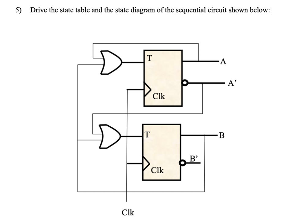
Answered: 5) Drive the state table and the state… | bartleby
Synchronous Sequential Logic
State Diagram and state table with solved problem on state ...

State diagram - Wikipedia
Final Exams Review

Solved) - Digital systems toggle flip flops state diagram and ...
Circuit, State Diagram, State Table Circuits with Flip-Flop ...
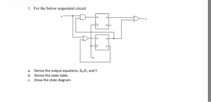
Solved) : 1 Sequential Circuit Derive Output Equations D ...
Circuit, State Diagram, State Table , g , Circuits with Flip ...

Solved) - Derive the state table and the state diagram of the ...
Chapter 5 Synchronous Sequential Logic Outline
Morris Mano Edition 3 Exercise 6 Question 9 (Page No. 253 ...
0 Response to "41 derive the state table and state diagram for the sequential circuit"
Post a Comment