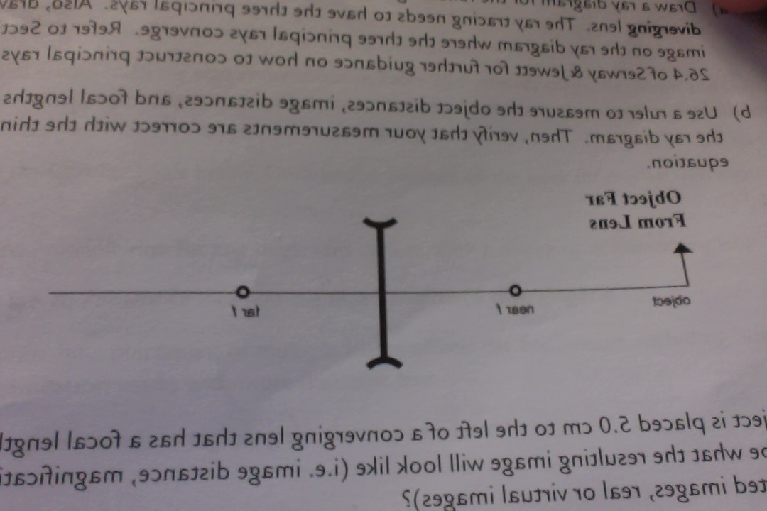
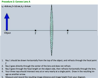
40 draw a ray diagram representing your experiment from part c
Ray diagrams and images - Lenses - Edexcel - GCSE Physics ... A virtual image appears to come from behind the lens. To draw a ray diagram: Draw a ray from the object to the lens that is parallel to the principal axis. Once through the lens, the ray should... › lens-design-spreadsheetOptical Lens Design Using a Spreadsheet / Excel: The Ultimate ... Looking at the cross sectional diagram and the ray diagram, using our pattern recognition and intuition as human beings can be a very powerful lens design process. Optimization with a computer is also powerful, but in a different way. Triplet design steps Step 1. Choose your glass. Glass. The biggest choice in lens design.
Selina Solutions Concise Physics Class 10 Chapter ... - BYJUS In each case, draw a diagram to show the path taken by the ray as it passes through the glass slab and emerges from it. Solution: (i) When the angle of incidence is 0 0 (ii) When the angle of incidence is 45 0. Question: 26. In the adjacent diagram, AO is a ray of light incident on a rectangular glass slab.
Draw a ray diagram representing your experiment from part c
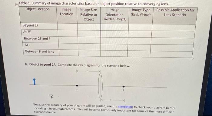
Light Reflection and Refraction Class 10 ... - Learn Cram Draw the following diagram in your answer book and show the formation of image of the object AB with the help of suitable rays. (CBSE 2008) Answer: Question 2. Draw ray diagrams to represent the nature, position and relative size of the image formed by a convex lens for the object placed: (a) At 2F Experiments with a single ray - IOPSpark A single ray hitting a lens (+ 7 D and - 7 D) Set up the lamp with a single slit, so that a single ray emerges. You can make the ray thinner and brighter by placing a + 7D lens just behind the slit. Watch what happens to the ray when it hits various places on a positive lens. Repeat the experiment using a negative lens. Concave Mirrors And Convex Mirrors - Image Formation, Ray ... Ray diagrams help us trace the path of the light for the person to view a point on the image of an object. Ray diagram uses lines with arrows to represent the incident ray and the reflected ray. It also helps us trace the direction in which the light travels. Plane Mirror vs Spherical Mirrors
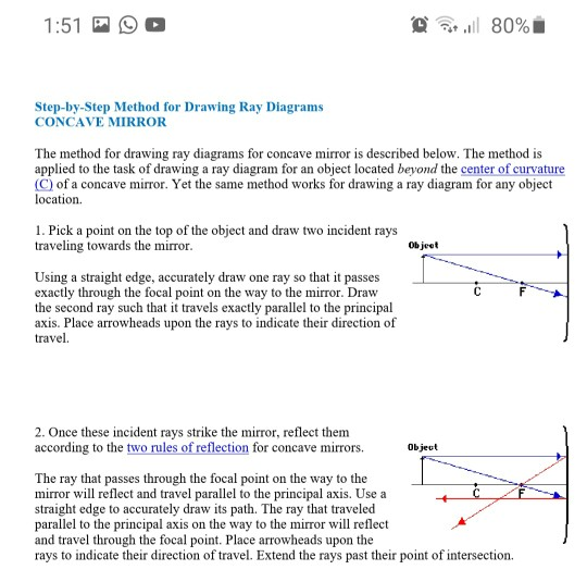
Draw a ray diagram representing your experiment from part c. Ray Diagrams & Lenses: Physics Lab - Video & Lesson ... In physics, ray diagrams show a ray of light's path from the object emitting light to a mirror, and then to a person's eye. Do this physics lab to learn about ray diagrams and lenses. PDF Physics 122 Assignment 8 Solutions Laura Lising Due ... - UMD in height, between your eyes and your feet. c) The most important part! Most people (over 90% when I asked the clicker question in lecture) think that you see more of your face when you back away. But that's not ... For the assignment you hand in, draw a diagram of the pinhole camera that explains PDF - PapaCambridge 7 (a) In the space below, draw a diagram to represent a sound wave. On your diagram, mark and label (i) two consecutive compressions and two consecutive rarefactions, (ii) the wavelength of the wave. [3] (b) Fig. 7.1 shows part of the electromagnetic spectrum. X-RAYS INFRA- RED Fig. 7.1 Physics Tutorial: Ray Diagrams - Concave Mirrors The method for drawing ray diagrams for concave mirror is described below. The method is applied to the task of drawing a ray diagram for an object located beyond the center of curvature (C) of a concave mirror. Yet the same method works for drawing a ray diagram for any object location. 1. Pick a point on the top of the object and draw two ...
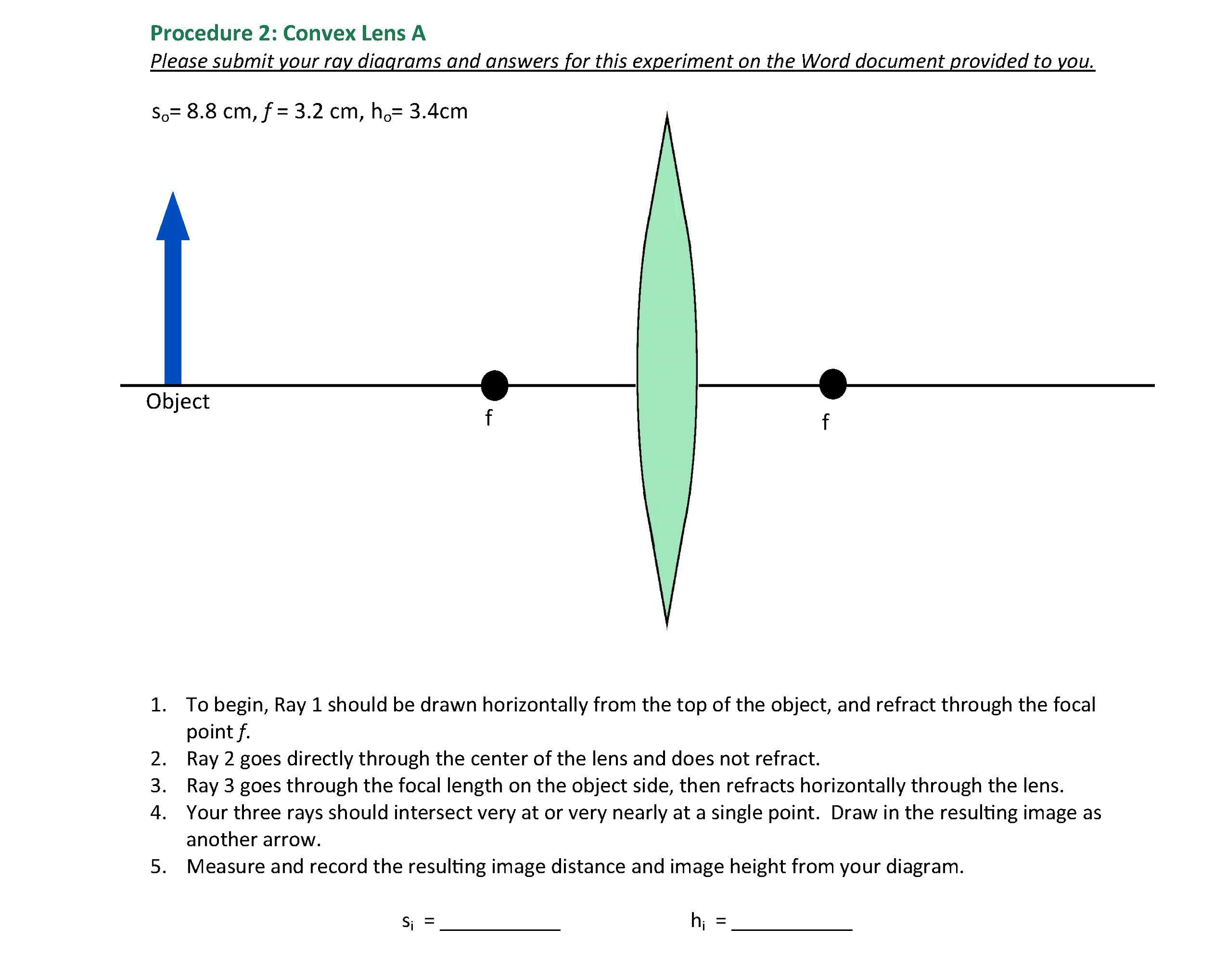
en.wikipedia.org › wiki › Chernobyl_disasterChernobyl disaster - Wikipedia The test was to be conducted during the day-shift of 25 April 1986 as part of a scheduled reactor shut down. The day shift crew had been instructed in advance on the reactor operating conditions to run the test and in addition, a special team of electrical engineers was present to conduct the one-minute test of the new voltage regulating system once the correct conditions had been reached. Convex Lens - Ray diagram, Image Formation, Table - Teachoo First, we draw a ray parallel to principal axis. So, it passes through focus after refraction. We draw another ray which passes through Optical Center. So, the ray will go through without any deviation. Where both rays meet is point A'. And the image formed is A'B'. This image is formed between F 2 and 2F 2. We can say that. PDF 3.1.Image formation by Mirrors and Lenses • A ray striking the center of the mirror reflects symmetrically around the mirror axis • A ray that passes through the center of curvature C reflects and passes back through itself •• Mirror C F axis R F 2 = Law of Reflection The position of the image can be determined from two rays from the object. • C F The image is real, inverted ... Light Reflection Questions - Practically Study Material Draw ray diagrams to represent the nature, position and relative size of the image formed by a convex lens for the object placed: (a) at 2F 1 (b) between F 1 and the optical centre O of lens: Draw ray diagrams to show image formation. Object at C - concave mirror Object beyond 2f - convex lens Object at infinity - concave lens.
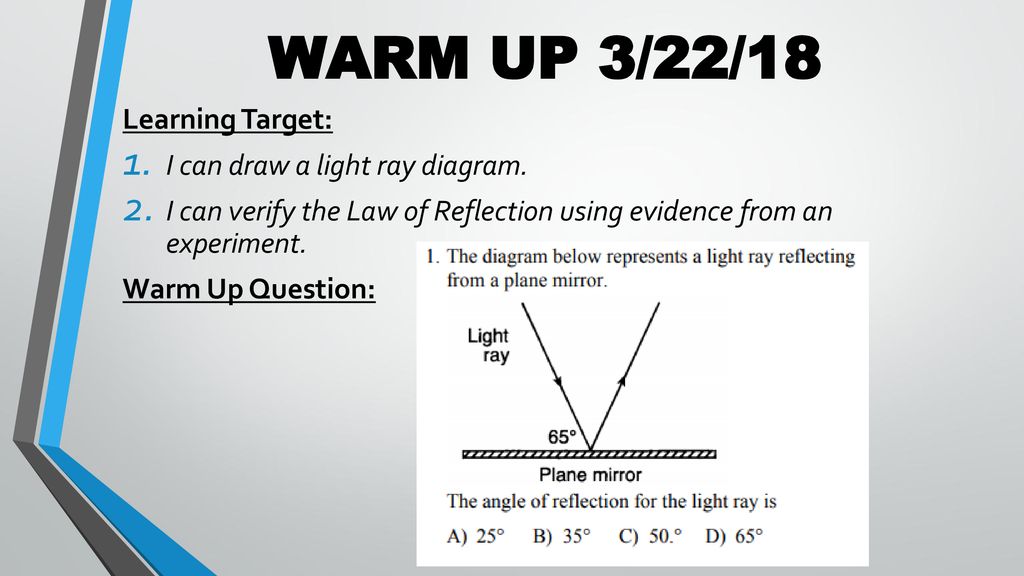
PDF Part 1 Angle of Incidence, Angle of Reflection Place the ray box, label side up, on a white sheet of paper on the table. Adjust the box so one white ray is showing. 2. Place the mirror on the table and position the plane surface of the mirror at an angle to the ray so that the both the incident and reflected rays are clearly seen. 3. PDF Free Response Questions Name: Answer KEY attached the diagram below draw the wave as it travels through medium B. [Show at least one full wave.] 15.The diagram below represents a transverse wave moving on a uniform rope with point A labeled as shown. On the diagram below, mark an X at the point on the wave that is 180° out of phase with point A. Image formation by convex and concave lens ray diagrams Image formation by convex lens ray diagrams. Image formation in a convex lens can be explained with the help of three principal rays shown in the figure. The ray parallel to the principal axis passes through the focal point after refraction by the lens. The ray passing through optical centre passes straight through the lens and remains undeviated. PDF Q1.€€€€€€€€€ (a)€€€€ The diagrams below show the patterns ... The diagram shows two rays of light coming from a small fish in some water. The rays enter a person's eye. (c)€€€€ The person sees an image of the fish under the water. On the diagram, draw construction lines to find the position of the image. Label the image I. 1 mark (d)€€€€ In some parts of the world, people catch fish using ...
Solved Direction: 1. Transfer the flash drawings on a graph ...
Solved Part A Consider the following diagrams noting that ... Transcribed image text: Part A Consider the following diagrams noting that the scale is different between diagrams. In these diagrams, C and F represent the center of curvature and the focal point of the convex mirror, respectively. The image formed by the mirror is obtained using the ray tracing technique.
Please help! I am not good a drawing ray diagrams, | Chegg.com
Geometrical Optics: Focal Length of a Concave Mirror and a ... Get the focal length from all measurements by (a) taking average of calculated f or (b) from u versus v graph or (c) from versus graph. 1.1 Concave Mirror. Look at the ray diagram shown in the figure. The distances are measured from the pole P. The incident ray (from the object to the mirror) is from the left to the right.
Physics Tutorial: Refraction and the Ray Model of Light
Ray diagrams - Reflection and refraction of light - CCEA ... On a sheet of white paper draw a pencil line - label this AB. Using a protractor, draw a normal at C, roughly the middle of AB. Draw a line at 20o to the normal. Position a plane mirror carefully...
Generation of ultra-short hydrogen atom pulses by bunch ...
PDF Fig. 4.1 (a) (b) - IGCSE Physics @ WOODSTOCK (c) On Fig. 4.1, draw another ray from point A to locate the image of point A. Label this image I. [3] (d) On the ray diagram in Fig. 4.1, the refraction is shown occurring at the centre line of the lens. State where the refraction actually occurs.
Solved a) draw a ray diagram for the following situation (an ...
PDF GEOMETRICAL OPTICS - Boston University 5. Redraw Figure 9 for your lab report to practice ray tracing . 6. Is the image upright or inverted? Is the magnification greater or less than one? Describe the image. Also include the following in your lab report as part of Experiment 1: 7. Make a ray diagram for an object placed closer to a diverging (concave) lens than the focal point.

a Schematic representation of a real image formed by using a ...
openstax.org › books › physics16.3 Lenses - Physics - OpenStax The ray diagram in Figure 16.33 shows image formation by the cornea and lens of the eye. The rays bend according to the refractive indices provided in Table 16.4 . The cornea provides about two-thirds of the magnification of the eye because the speed of light changes considerably while traveling from air into the cornea.

draw a ray diagram to show the path of the refracted ray in ...
(a) Draw ray diagram of refraction of light through a ... Click here👆to get an answer to your question ️ (a) Draw ray diagram of refraction of light through a prism and explain the phenomenon of dispersion of light.(b) Write the formula for lens power and define its unit.
Happy Wednesday! Find your new seats - ppt download
PDF LABORATORY I: GEOMETRIC OPTICS - University of Minnesota On your original diagram, add the light rays that would make it from the light source in its new position to the screen. How would the position of the light spot on the screen change? 3. Draw a new ray diagram for a similar situation with a new light source, in the shape of a vertical arrow that emits light from all parts.

Convex & Concave Lens Ray Diagrams | How to Draw Ray Diagrams ...
opentextbc.ca › universityphysicsv3openstaxAtomic Spectra and X-rays – University Physics Volume 3 A standard X-ray image provides a two-dimensional view of the object. However, in medical applications, this view does not often provide enough information to draw firm conclusions. For example, in a two-dimensional X-ray image of the body, bones can easily hide soft tissues or organs.

Images Formed by Concave Mirrors | CK-12 Foundation
PDF PHYS 4D Solution to HW 4 - University of California, San Diego Figure 6: Problem 32-21 (c) Compute the image size, using Eq. 32-3. Solution: m = di do hi = mho = di do ho = 6.0cm 18cm 3.0mm = 1.0mm. Problem Giancoli 32-21 (II) Show, using a ray diagram, that the magni cation m of a convex mirror is m = di/do, just as for a concave mirror.[Hint: Consider a ray from the top of the object that re

Draw a ray diagram to show the refraction of a monochromatic ...
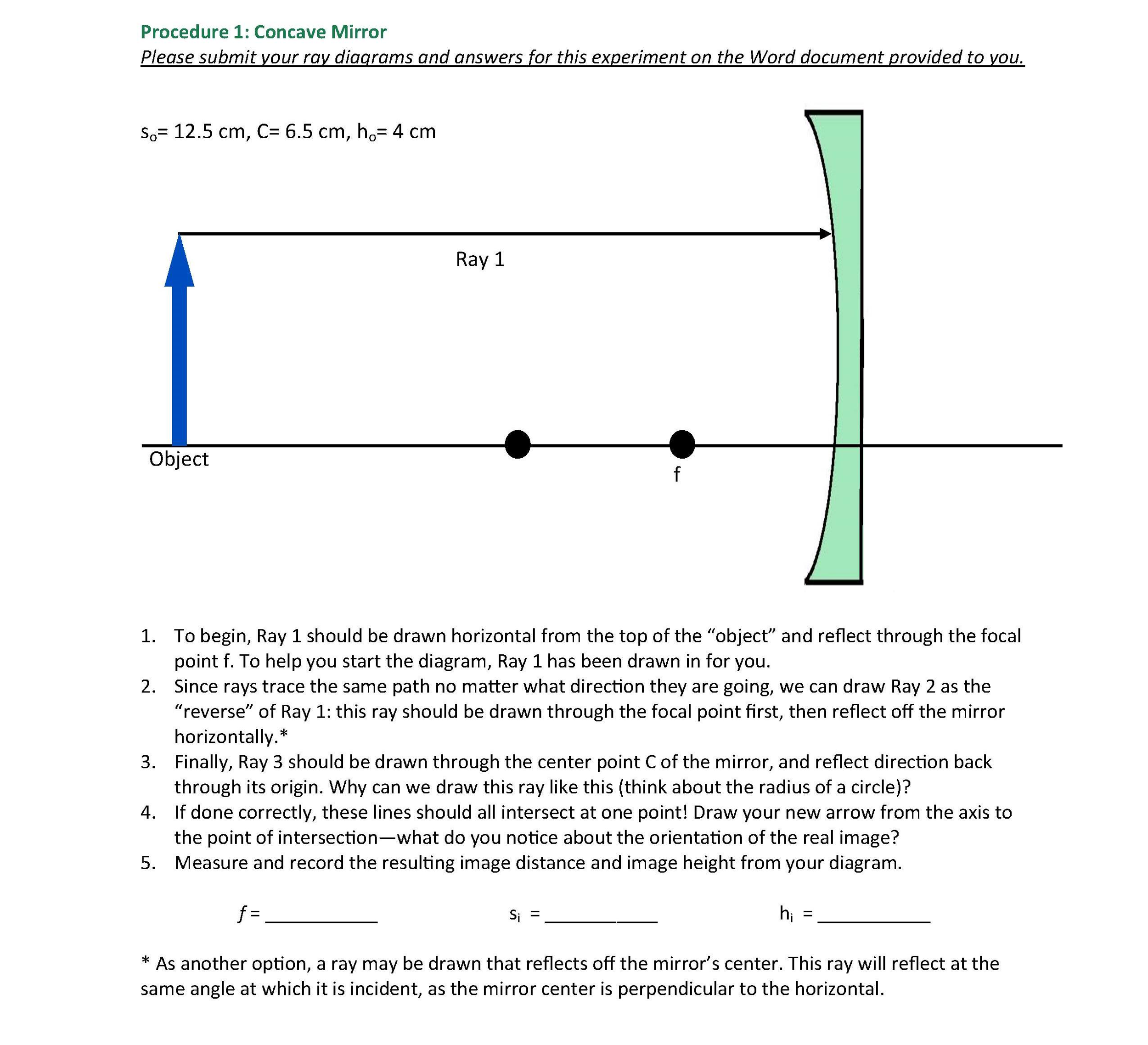
Solved object 3. The diverging mirror shown above has a ... This ray heads toward F, emerging parallel to the principal axis after reflection. Ray 2 is analogous to ray 1, except that the reflected, rather than the incident, ray is parallel to the principal axis. Ray 3. This ray travels toward the center of curvature C; as a result, the ray strikes the mirror perpendicularly and reflects back on itself.
AP Physics 2 Student Sample Responses to Question 3 - 2017 Exam
What is CRT (Cathode Ray Tube)? definition, block diagram ... CRT parts are confined in a glass envelope in order to permit free movement of the electron from an end to the other. Working of Cathode Ray Tube. The main parts of CRT are responsible for the working of it that is explained below-Electron gun. The electron gun is the originator of focused accelerated electron beam. It consists of a heater, a ...
Solved Down below is one lab question and pictures of the ...
Physics Tutorial: Ray Diagrams for Plane Mirrors Drawing Ray Diagrams - a Step-by-Step Approach. This section of Lesson 2 details and illustrates the procedure for drawing ray diagrams. Let's begin with the task of drawing a ray diagram to show how Suzie will be able to see the image of the green object arrow in the diagram below. For simplicity sake, we will suppose that Suzie is viewing the ...
![PDF] Dynamic transition between Fresnel and Fraunhofer ...](https://d3i71xaburhd42.cloudfront.net/76e23bfc7dc89daa246d06ed02350a2022265719/4-Figure2-1.png)
PDF] Dynamic transition between Fresnel and Fraunhofer ...
physical chemistry: kinetics Flashcards | Quizlet Draw a diagram of a suitable apparatus needed to perform the experiment outlined in part (a). Include in your diagram a method for collecting and measuring the carbon dioxide. The apparatus should be airtight.
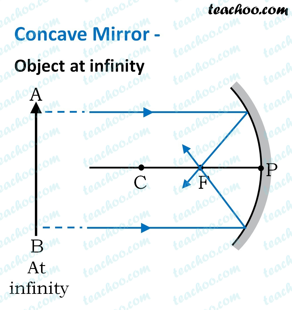
Concave Mirror - Ray diagram, Image Formation, Table - Teachoo
PDF Chapter 22: Mirrors and Lenses - SharpSchool your head. Use the sketch in Fig. 22.3a to help draw a ray diagram. The vertical distance between the feet and eyes is h 1; the vertical distance between the top of the head and the eyes is h 2; and h 1 h 2 h (Fig. 22.3b). You will see a toe if a ray from your toe reaches your eye after reflection. This is ray 1 on the diagram.
Solved Down below is one lab question and pictures of the ...
Concave Mirrors And Convex Mirrors - Image Formation, Ray ... Ray diagrams help us trace the path of the light for the person to view a point on the image of an object. Ray diagram uses lines with arrows to represent the incident ray and the reflected ray. It also helps us trace the direction in which the light travels. Plane Mirror vs Spherical Mirrors
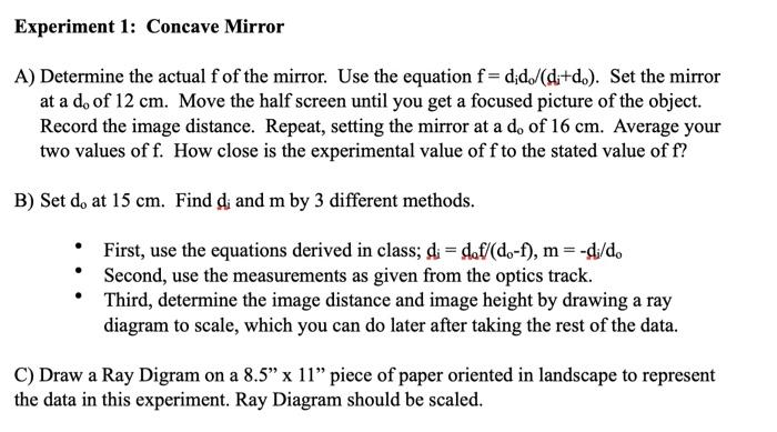
V. Developing Mathematical Representations of Pinhole ...
Experiments with a single ray - IOPSpark A single ray hitting a lens (+ 7 D and - 7 D) Set up the lamp with a single slit, so that a single ray emerges. You can make the ray thinner and brighter by placing a + 7D lens just behind the slit. Watch what happens to the ray when it hits various places on a positive lens. Repeat the experiment using a negative lens.
Please help! I am not good a drawing ray diagrams, | Chegg.com
Light Reflection and Refraction Class 10 ... - Learn Cram Draw the following diagram in your answer book and show the formation of image of the object AB with the help of suitable rays. (CBSE 2008) Answer: Question 2. Draw ray diagrams to represent the nature, position and relative size of the image formed by a convex lens for the object placed: (a) At 2F
Physics Tutorial: Ray Diagrams for Plane Mirrors

Draw a ray diagram to show the refraction of light through a ...
Solved UMUC NSCI 100Lab 6: LightExperiment 1: Ray | Chegg.com

Convex & Concave Lens Ray Diagrams | How to Draw Ray Diagrams ...

Scientific method - Wikipedia
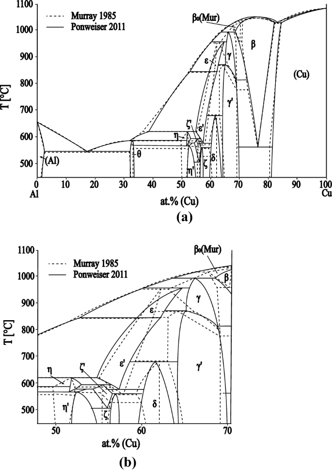
Experimental Description of the Al-Cu Binary Phase Diagram ...

a) Draw ray diagram of refraction of light through a prism ...
Physics Tutorial: Ray Diagrams - Concave Mirrors
09b_Drawing Ray Diagrams

Draw a ray diagram represent the nature , position and ...
![Expert Verified] draw the ray diagram in each case to show ...](https://hi-static.z-dn.net/files/d68/483631afd234286cd5ecd752527d1aa3.jpg)
Expert Verified] draw the ray diagram in each case to show ...

q39-draw-a-ray-diagram-to-show | LIDO
Solved 1. Converging Lenses The pre-lab notes described how ...

Ray diagram for image formation of an extended object ...

5.3 Properties of light: revision | Geometrical optics | Siyavula
Solved Experiment 1: Ray Diagrams To complete this lab, you ...

Robert A. Millikan and the Oil Drop Experiment: The Physics ...

Draw ray diagrams showing the image formation by a convex lens when an object is placed
Solved Experiment 1: Ray Diagrams To complete this lab, you ...
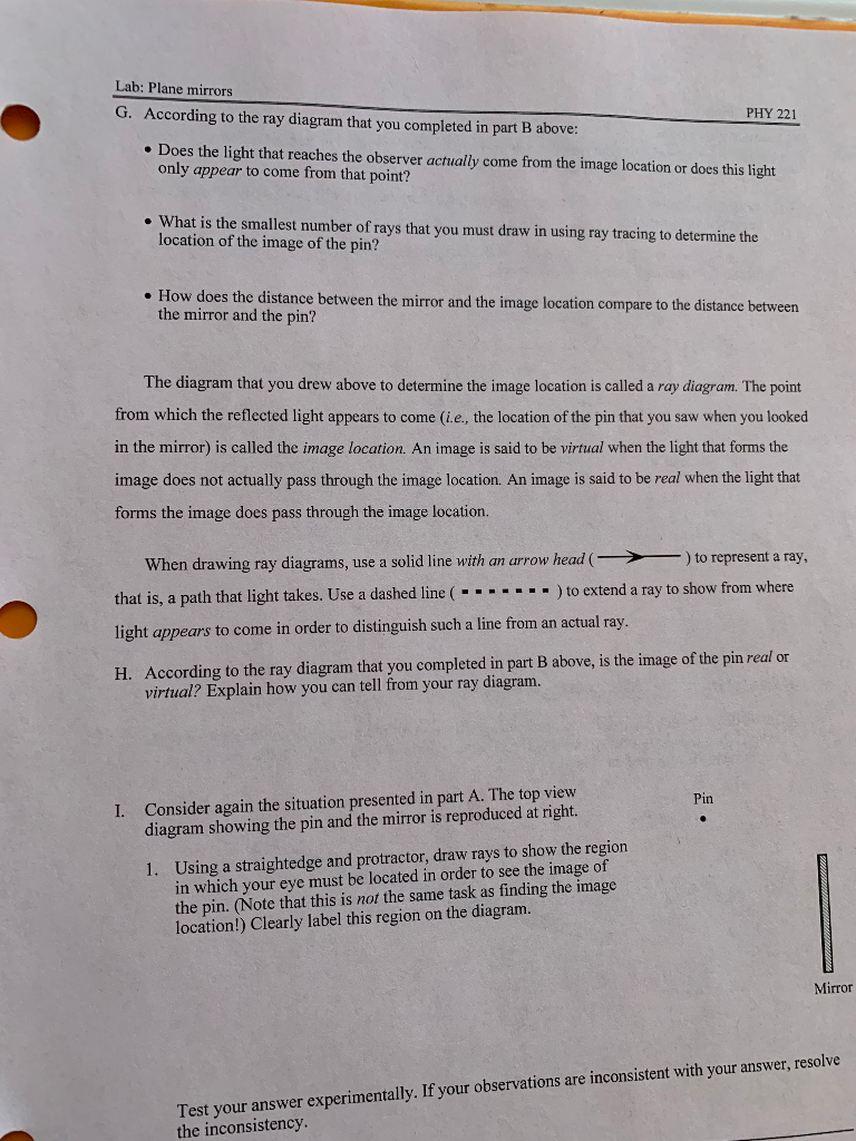
Lab: Plane mirrors PHY 221 G. According to the ray | Chegg.com
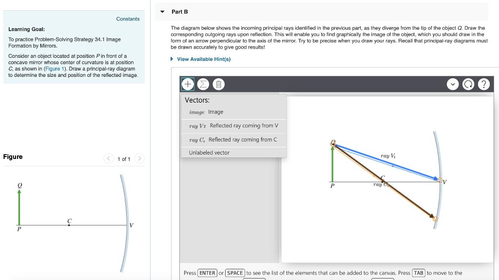
Solved The diagram below shows the incoming principal rays ...

Unit 3 Scarcity, work, and choice – The Economy
0 Response to "40 draw a ray diagram representing your experiment from part c"
Post a Comment