38 shear diagram cantilever beam
Solution to Problem 410 | Shear and Moment Diagrams ... Solution to Problem 410 | Shear and Moment Diagrams Problem 410 Cantilever beam carrying the uniformly varying load shown in Fig. P-410. Click here to read or hide the general instruction Write shear and moment equations for the beams in the following problems. In each problem, let x be the distance measured from left end of the beam. Shear Force and Bending Moment diagram for cantilever beam ... In the other words, bending moment is the unbalancing moment of forces on any one side of the cross-section considered. Below diagrams are explain the shear force and bending moment diagram for Cantilever Beam. Concentrated load at the free end Uniformly distributed load
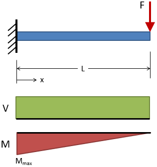
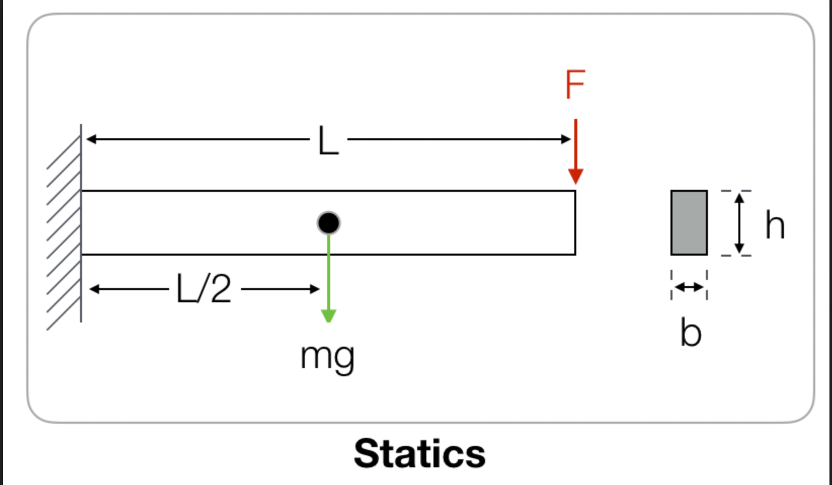
Cantilever Beam Calculator - calcresource Cantilever beam with point force at the tip. The force is concentrated in a single point, located at the free end of the beam. In practice however, the force may be spread over a small area, although the dimensions of this area should be substantially smaller than the cantilever length.
Shear diagram cantilever beam
How To Calculate Shear Strain: Process,Formula,Example And ... alpha is the angular shear strain. Shear stress in rectangular beam. A rectangular beam is a beam whose cross section is rectangular or square. The amount of shear stress experienced by different points of cross section are different. This happens because the distance of the point from the application of force is variable for different points. So different amount of force acting on … Draw the shear force and bending moment diagrams for ... Civil Engineering. Civil Engineering questions and answers. Draw the shear force and bending moment diagrams for the following cantilever beam using the graphical method. Use an appropriate scale. 25 KN 5 kN/m 8 kN/m 50 kN.m 2 m 1 m 1 m 1 m 3 m Attach File row My Computer. Bending moment and shear force diagram of a cantilever beam Sep 11, 2017 · Bending moment and shear force diagram of a cantilever beam By sanjay sharma 11 Sep 2017 13 Oct 2017 In this article Learn :cantilever beam Bending moment diagram B.M.D. and shear force diagram S.F.D. of a cantilever beam having point load at the end,several point loads,U.D.L.
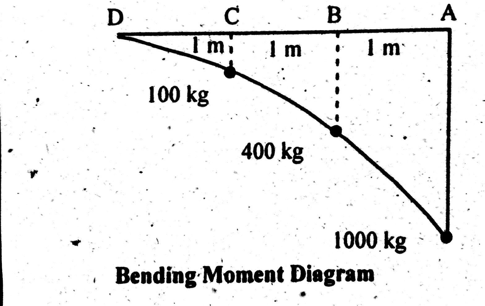
Shear diagram cantilever beam. Shear Force and Bending Moment Diagram for Cantilever Beam ... Today we will see here the concept to draw shear force and bending moment diagrams for a cantilever beam with a point load or force acting at free end with the help of this post.Let us consider one beam AB of length L as displayed in following figure. Beam Deflection and Stress Calculators with Formulas Combined Stress Circular Cantilever Beam in Direct Compression and Bending Stress Equations and Calculator Circular Cantilever Beam in Direct Compression. For every calculated normal stress there is a corresponding induced shear stress; the value of the shear stress is equal to half that of the normal stress. Everything You Should Know About Cantilever Beams - The ... Figure-3: Bending and Shear Force Diagram of Cantilever Beam with Point Load at Free End The shear force at the fixed support A is determined by keeping the section at A, which gives the shear force Ra=W; and moment Ma = W.l. based on which the shear force and bending moment diagram are developed. Shear Force & Bending Moment Diagram of Cantilever Beam ... This shows shear force is maximum at fixed end and minimum at free end of cantilever beam. Shear Force Diagram Bending Moment Bending moment at point D = B.M (D) = 0 Bending moment at point C = B.M (C) = - (100×1) = -100 kg.m Bending moment at point B = B.M (B) = - (100×2 +200×1) B.M (B) = -400 kg.m
Shear And Moment Diagram Cantilever Beam - The Best Picture ... Jun 23, 2020 · 4 5 Shear Force And Bending Moment Of Cantilever Beams Strength Materials. Sketch The Shear And Bending Moment Diagrams For Cantilever Beam Shown Given Following Parameters Omega A L Study. Solved Draw The Shear Force And Bending Moment Diagrams For Cantilever Beam Determine A Position Of Point Contraflexure Bend Course Hero. Free Civil Engineering Files for Downloading ... Footing Design of Shear Wall per ACI 318-14. Meyerhof bearing capacity calculator. View all files of Foundation Analysis and Design; Load Calculation; Beam Analysis EXCEL Spreadsheet Wind Loading Calculator Sheet (Per ASCE 7-05 Code) Load Analysis Of A Building EXCEL Estimator Spreadsheet. Wind Loading Calculator Sheet (Per ASCE 7-02 Building Code) ... 3. BEAMS: STRAIN, STRESS, DEFLECTIONS The beam, or ... beam, a beam fixed (or restrained) at the left end and simply supported near the other end (which has an overhang) and a beam fixed (or restrained) at both ends, respectively. Cantilever beams and simple beams have two reactions (two forces or one force and a couple) and these reactions can be obtained from a free-body diagram of the beam PDF 4. Bending Moment and Shear Force Diagram The shear force will be zero at each end of the beam unless a point force is applied at the end. Construction of bending moment diagram xThe bending moment diagram is obtained by proceeding continuously along the length of beam from the left hand end and summing up the areas of shear force diagrams using proper sign convention.
Solution to Problem 414 | Shear and Moment Diagrams ... Problem 414 Cantilever beam carrying the load shown in Fig. P-414. [collapse collapsed title="Click here to read or hide the general instruction"]Write shear and moment equations for the beams in the following problems. In each problem, let x be the distance measured from left end of the beam. Also, draw shear and moment diagrams, specifying values at all change of loading Ansys cantilever beam analysis : Shear force and Bending ... learn how to make shear force and bending moment diagrams(beam diagrams) in ansys workbench.How to use ansys beam tool to calculate combined bending stress f... Shear Force and bending moment diagram - ExtruDesign Shear force between any two vertical loads will be constant. And hence the shear force between the two vertical loads will be horizontal. The bending moment at the two ends of the simply supported beam and at the free end of a cantilever will be zero. Shear force and Bending moment Diagram for a Cantilever beam with a Point load at the free end PDF Chapter 4 Shear and Moment In Beams - ncyu.edu.tw A cantilever beam is built into a rigid support at one end, with the other end being free, as shown in Fig.4.1(b). The built-in support ... The bending moment and shear force diagrams of the beam are composites of the V and M diagrams of the segments. These diagrams are usually discontinuous, or have discontinuous
shear force and bending moment diagram for cantilever beam
Cantilever Beam | Advantages of a Cantilever Beam ... Shear Force and Bending Moment Diagram for Cantilever Beam with Point Load at the Free End L is the length shown in Fig when a point is a fixed end when point b is the free end. For calculation of shear force. Suppose the x-x section is the distance from a point B to x. So the shear force on the x-x section. Fx = + W. The shear force at point A,
Shear Force & Bending Moment Diagram of Cantilever Beam ...
BENDING FREQUENCIES OF BEAMS, RODS, AND PIPES Revision S Cantilever Beam I Consider a mass mounted on the end of a cantilever beam. Assume that the end-mass is much greater than the mass of the beam. Figure A-1. E is the modulus of elasticity. I is the area moment of inertia. L is the length. g is gravity. m is the mass. The free-body diagram of the system is Figure A-2. R is the reaction force. M R
Bending Moment Diagram - BrainDuniya
Propped Cantilever Beam Calculator 2021-07-09 · Calculator 1: This propped cantilever beam calculator is programmed to calculate the deflection profile, slope, shear force diagram (sfd), bending moment diagram (bmd) and end reactions with formulas for uniformly distributed load (udl), uniformly varying load (uvl), triangular load and trapezoidal loading.

SHEAR FORCE AND BENDING MOMENT DIAGRAM FOR CANTILEVER BEAM ...
How to Draw Shear Force & Bending Moment of Cantilever ... Draw shear force and bending moment diagram of cantilever beam carrying UDL and point loads. As shown in figure below; Solution. Shear Force. Let first draw shear force diagram. To draw shear force diagram, first find value of shear force at point C,B and A. Shear force will increase from left towards right.
BEAM FORMULAS WITH SHEAR AND MOM
How to Calculate Bending Moment Diagram? | SkyCiv 2021-11-11 · Once you have the reactions, draw your Free Body Diagram and Shear Force Diagram underneath the beam. Finally calculating the moments can be done in the following steps: 2. From left to right, make “cuts” before and after each reaction/load. To calculate the bending moment of a beam, we must work in the same way we did for the Shear Force ...
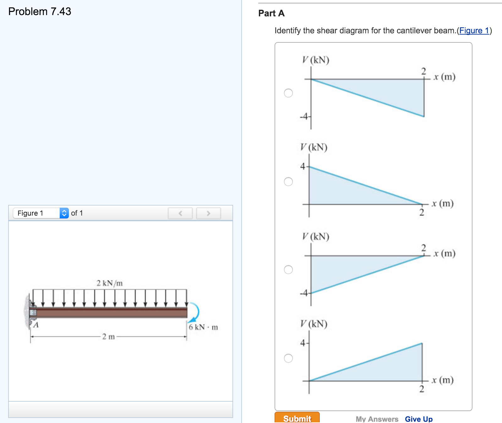
Solved Indentify the shear diagram for the cantilever | Chegg.com
Draw The Shear Diagram For Cantilever Beam - The Best ... Shear Force Bending Moment Diagram Of Cantilever Beam Exles Ering Intro A Cantilever Beam Is Subjected To Various Lo As Shown In Figure Draw The Shear Force Diagram And Bending Moment For Ethiotutors Solved Draw The Shear Force Diagram And Ben 329 6 1 Draw The Shear And Moment Diagrams For Aeros
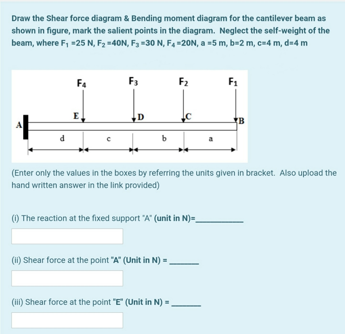
Answered: Draw the Shear force diagram & Bending… | bartleby
Beam Forces & Moments - Engineering Library Split the beam at the pinned support as in Figure 1-31(b) and find M A from the equations of statics. Consider the right section of the beam as a single beam simply supported at both ends as in Figure 1-31(b). Find the moment diagram for this beam as in Figure 1-31(c). A is the area of this moment diagram and C is the centroid of this area.

Shear Force and bending moment diagram - ExtruDesign
PDF Shear force and bending moment of beams Beams Propped Cantilever Beam When a support is provided at some suitable point of a Cantilever beam, in order to resist the deflection of the beam, it is known as propped Cantilever beam. Fig. 11. Propped Cantilever beam 5. Fixed Beam A beam having its both ends rigidly fixed or built0in to the supporting walls or colums is known as fixed beam. Fig. 12.
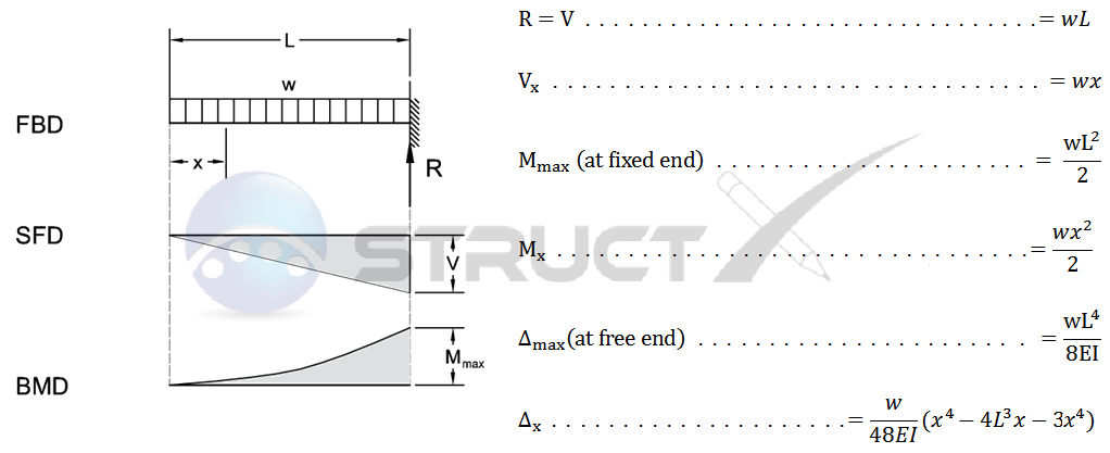
Cantilever Beam - Uniformly Distributed Load
6.2 Shear/Moment Diagrams - Engineering Mechanics: Statics Draw the shear force and bending moment diagrams for the cantilever beam supporting a concentrated load of 5 lb at the free end 3 ft from the wall. 1. Draw a FBD of the structure . 2. Calculate the reactions using the equilibrium equations (may not need to do this if choosing a cantilever beam and using the free side for the FBD).

Beam Reactions and Diagrams – Strength of Materials ...
Answered: Draw the shear and moment diagrams for… | bartleby Draw the shear and moment diagrams for the cantilever beam shown and determine the maximum absolute value of the shear and bending moment. Indicate the degree of each curve. You may use the method of sections, area method, or both. 15 kN/m 8 kN 5 kN/m A В 20 kN/m 8 kN/m E 2 m →e 3 m 6 m Question SHEAR AND BENDING MOMENT DIAGRAM
Shear Force and Bending Moment Diagram for Cantilever Beam ...
PDF Reinforced Concrete Cantilever Beam Analysis and Design ... Shear Design Figure 5 - Shear Diagram for Cantilever Beam VVd @ s Shear strength provided by concrete 2 ' IIV f b d c c w u u u u ACI 318-14 (Eq. 22.5.5.1) IVc s s 2 c u V V I Since V u > ϕV c /2, shear reinforcement is required. Try # 4, Grade 60 two-leg stirrups (A v = 2 x 0.20 = 0.40 in.2). The nominal shear strength required to be ...
Solved Draw the shear-force and bending-moment diagrams for ...
Free Online Beam Calculator | SkyCiv Engineering Free online beam calculator for generating the reactions, calculating the deflection of a steel or wood beam, drawing the shear and moment diagrams for the beam. This is the free version of our full SkyCiv Beam Software. This can be accessed under any of our Paid Accounts, which also includes a full structural analysis software.
Beam Stress & Deflection | MechaniCalc
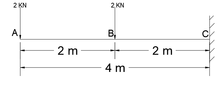
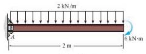
Shear Force and Bending Moment Diagram for Cantilever Beam ... Shear Force and Bending Moment Diagram of Cantilever beam when point load is applied. From the figure we have the value of load at point A and point B. So let’s draws the shear force diagram with the help of these loading. Bending moment at point A is zero. Bending moment at point B= -2*2 = 4 KN-M. Bending moment at point C= -2*4-4*2 = 12 KN-M.
Solved Problems) 6-4, Bending, Mechanics of Materials by R C ...
Beam Reactions and Diagrams – Strength of Materials ... At the wall of a cantilever beam the shear force equals the vertical reaction at the wall. At the beam’s free end the shear force is zero. On any beam segment where no loads are applied, the shear force remains constant (horizontal line). A point load or reaction on a shear force diagram generates an abrupt change in the graph, in the direction of the applied load. A uniform …

GATE & ESE - Shear Force and Bending Moment Diagram for ...
Lecture 2 - Shear and Bending Moment and Review of Stress 3.2 - Shear Force & Bending Moment Diagrams What if we sectioned the beam and exposed internal forces and moments. This exposes the internal Normal Force Shear Force Bending Moment ! What if we performed many section at ifferent values Of x, we will be able to plot the internal forces and bending moments, N(x), V(x), M(x) as a function Of position!

Bending moment and shear force diagram of a cantilever beam
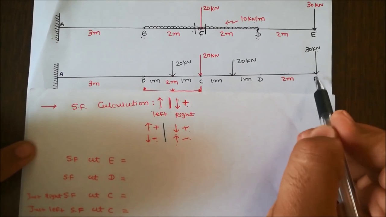
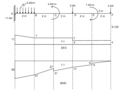
PDF Module -4 Shear Force and Bending Moment Diagrams Variation of shear force and bending moment diagrams S.N Point Load UDL UVL Shear Force Constant Linear Parabolic Bending Moment Linear parabolic Cubic WORKED EXAMPLES 1) A cantilever beam of length 2 m carries the point loads as shown in Fig. Draw the shear force and B.M. diagrams for the cantilever beam. Shear Force Diagram S.F. at D, F D
Cantilever beam - shear force diagrams, Mechanical Engineering
PDF CHAPTER 2 Shear Force And Bending Moment a) Calculate the shear force and bending moment for the beam subjected to a concentrated load as shown in the figure. Then, draw the shear force diagram (SFD) and bending moment diagram (BMD). b) If P = 20 kN and L = 6 m, draw the SFD and BMD for the beam. P kN L/2 L/2 A B EXAMPLE 4

structural engineering - Problem while solving for the moment ...
Draw the shear and moment diagrams for the cantilevered beam When loads are applied on a beam, it develops an internal shear force and bending moment which varies from point to point along the axis of the beam. The shear and bending moment functions can be plotted on a graph paper, taking the beam as a reference, called shear force and bending moment diagrams.

Statics eBook: Shear and Moment Diagrams II
Draw Bending Moment & Shear Force Diagrams - Cantilever Beam This video explains how to draw shear force diagram and bending moment diagram with easy steps for a cantilever beam loaded with a concentrated load. Shear f...

Civil Engineering: Shear Force and Bending Moment diagram for ...
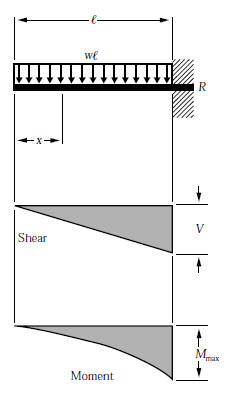
BEAM DESIGN FORMULAS WITH SHEAR AND MOMENT AMERICAN WOOD COUNCIL w R V V 2 2 Shear M max Moment x 7-36 A ab c x R 1 R 2 V 1 V 2 Shear a + — R 1 w M max Moment wb 7-36 B Figure 1 Simple Beam-Uniformly Distributed Load

Shear Force and Bending Moment... - The Civil Engineering ...
Bending moment and shear force diagram of a cantilever beam Sep 11, 2017 · Bending moment and shear force diagram of a cantilever beam By sanjay sharma 11 Sep 2017 13 Oct 2017 In this article Learn :cantilever beam Bending moment diagram B.M.D. and shear force diagram S.F.D. of a cantilever beam having point load at the end,several point loads,U.D.L.
6.2 Shear/Moment Diagrams – Engineering Mechanics: Statics
Draw the shear force and bending moment diagrams for ... Civil Engineering. Civil Engineering questions and answers. Draw the shear force and bending moment diagrams for the following cantilever beam using the graphical method. Use an appropriate scale. 25 KN 5 kN/m 8 kN/m 50 kN.m 2 m 1 m 1 m 1 m 3 m Attach File row My Computer.

Cantilever Beam with Uniformly Distributed Load. | Download ...
How To Calculate Shear Strain: Process,Formula,Example And ... alpha is the angular shear strain. Shear stress in rectangular beam. A rectangular beam is a beam whose cross section is rectangular or square. The amount of shear stress experienced by different points of cross section are different. This happens because the distance of the point from the application of force is variable for different points. So different amount of force acting on …
Given a wall-mounted cantilever beam, describe the shear ...
![Solved]: Draw the shear force diagram and the ben](https://media.cheggcdn.com/study/23c/23cdcae5-b969-43bb-a79c-ca78d881f022/image)
Solved]: Draw the shear force diagram and the ben

Cantilever beam response: support reactions, beam moment ...
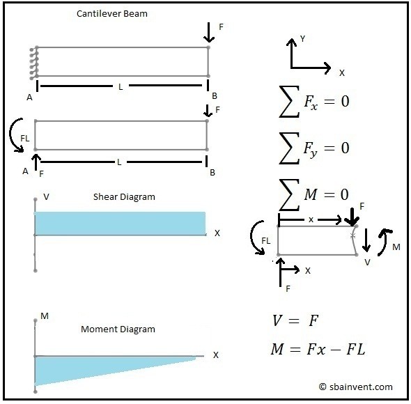
Shear and Moment Diagrams - S.B.A. Invent
Mechanics of Materials Chapter 4 Shear and Moment In Beams
Solved Problem 7.48 Part A Draw the shear diagram for | Chegg.com

A cantilever beam is subjected to various loads as shown in ...
![[Ex. 07] Shear Moment Diagram Cantilever Beam Distributed Load Part II](https://i.ytimg.com/vi/uvVixOLFa0c/maxresdefault.jpg)
[Ex. 07] Shear Moment Diagram Cantilever Beam Distributed Load Part II

Cantilever beam with shear force load. | Download Scientific ...

Shear Force and Bending Moment Diagram for Cantilever Beam ...
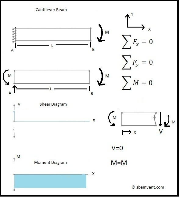
Shear and Moment Diagrams - S.B.A. Invent
How To Draw Shear Force And Bending Moment Diagram In Case Of ...

Moment Diagrams Constructed by the Method of Superposition ...

Sketch the shear and bending moment diagrams for the ...

Draw shear force and bending moment diagram for cantilever ...
0 Response to "38 shear diagram cantilever beam"
Post a Comment