41 Pv System Grounding Diagram
Installation is almost complete! 5 Powerwalls and 400A ... Fortunately the NEC has move beyond the idea that PV installs require extra earthing. They just need an EGC in the feeder to the inverter. Every service requires earthing, and if ground rods are to provide the required earthing, you need two of them, at least 6' apart, each one with at least 8' of length in contact with the earth. Cheers, Wayne. etap.com › productProducts | ETAP - Power Management System System Grounding & Earthing . DC Load Flow . ... One-Line Diagram (Aero Space) Unit Commitment . ... PV Array & Solar Panel .
Solar Power System Diagram | 4 Basic Building Blocks Solar power systems vary widely in their power producing capabilities and complexity. But I wanted to sketch a simple basic solar power system diagram that shows the building blocks. Regardless of a given system's capacities and specifications, there's a common thread among most of them: The basic building blocks of its major components. 1.

Pv system grounding diagram
› docs › fy16ostiField Guide for Testing Existing Photovoltaic Systems for ... grounding electrode system or is functionally grounded through an overcurrent protection device (OCPD) to a grounding electrode system. Grounding of exposed metal surfaces likely to become energized, also known as equipment grounding, is a requirement for all electrical systems governed by the NEC. Installation is almost complete! 5 Powerwalls and 400A ... We have had a 7 kW PV system for a while, and with the SMA Secure Power Supply at least we could do basic things while the sun was out. If the power was off, we ran an extension cord out to the PV ground mount and that would keep the refrigerator and computers alive. We are out of power an average of 10 days per year, and it is always a huge pain. Analysis and design of solar PV system using Pvsyst ... Finally, the deficit diagram is calculated for the whole year .In addition, the PVSyst simulation software is used to do a performance review of the proposed stand-alone PV system. The simulation results include the total energy provided by the PV array, unused energy, energy supplied to the load, PV conversion efficiency, device losses, output ...
Pv system grounding diagram. Information Bulletin Ib-023 solar PV system at the time of application submittals: a. City Permits/Documents. ... One-line diagram of the system Specify grounding/bonding, conductor type and size, conduit type and size and number of conductors in each section of conduit If batteries are to be installed, include them in the diagram and show their locations and ... Photovoltaics and electricity - U.S. Energy Information ... How photovoltaic systems operate. The PV cell is the basic building block of a PV system. Individual cells can vary in size from about 0.5 inches to about 4 inches across. However, one cell only produces 1 or 2 Watts, which is only enough electricity for small uses, such as for powering calculators or wristwatches. Bifacial calculations - PVsyst's forum Posts: 4. In your help you say that for bifacial « 6.64 is correct, but doesn't take some marginal contributions into account, like the Beam on the rear side, or the reflexions of the near ground on the front side.". Then you say "6.65 add 2 new contributions: beam component on the rear side". Disconnect switch between solar panels and solar charge ... Disconnect switch between solar panels and solar charge controller. 03-23-2021, 07:46 PM. I search for this and re-learned that I need a disconnect switch between my panels and the MPPT solar controller. However the details of what folks have used are sparse. Some videos and posts are using a bin rail circuit breaker to act as a switch.
How to Wire a Solar Charge Controller for ... - EXPLORIST.life This is the solar charge controller equipment ground screw: You need a wire with a 1/4″ wire lug on one side and a 5/16″ wire lug on the other side to make this connection. Remove the Screw and washers using a phillips head screwdriver. Place the 1/4″ wire lug against the heat sink. Replace the washers and screw. Inverter Wiring Diagram For House - The Wiring Inverter Home Wiring Diagram with Inverter Home Wiring Diagram, image size 600 X 413 px, and to view image details please click the image. Wiring Diagram for Inverter Charger Best Marine Inverter Charger. A junction box out at the PV panel array is used to make the connection from the first micro-inverter to the wiring that goes to the house. Ground-Mounted Solar: Top 3 Things You Should Know ... 3. Ground-mounted solar panel systems offer benefits for all homeowners. Even if you are a good candidate for a rooftop solar energy system, there are many benefits to choosing a ground-mounted solar panel system. First, ground-mounted solar panel systems are very easy to place, because they can be located on open land. Ground reflection on front side - PVsyst's forum The "Ground reflection on front side" is a by-product of the Bi-facial model. It is not possible to calculate it with "normal" systems, without several additional parameters and a calculation model that we don't have at disposal at the moment (the bi-facial model is specific for unlimited sheds).
Solar Panel Wiring Basics: An Intro to How ... - Aurora Solar Basic Concepts of Solar Panel Wiring (aka Stringing) To have a functional solar PV system, you need to wire the panels together to create an electrical circuit through which current will flow, and you also need to wire the panels to the inverter that will convert the DC power produced by the panels to AC power that can be used in your home and sent to the grid. Camper Wiring Diagram w/ 3000w Inverter ... - EXPLORIST.life This DIY camper solar wiring diagram and parts list is perfect for ground-up electrical installs into campervans, skoolies, or expedition vehicles. This system is most suitable for systems that do not have a pre-existing house electrical system installed. This diagram features: 2000W Inverter Charger; 200+ Amp Hours of Battery Storage Capacity Solar battery charge controller wiring diagram and steps ... 4. PV modules start to generate electricity as soon as they face the sun. Here's the diagram, which gives an idea on how to connect these parts of a solar panel system together. We have one 12V KiloVault solar battery, one 96A Midnite MPPT-controller and two 330W Panasonic solar panels. IAEI Magazine - IAEI Magazine IAEI's Online Training allows you to learn at your own pace or live with an expert instructor, from the comfort of your laptop or PC. Choose topics from a full list of courses covering electrical topics that cover what you need to know from the NEC and other electrical codes and standards.GET YOUR CEUS TODAY
Photovoltaic_System_Module_Wiring - reeetech
Solis Seminar- Solution For PID Recovery - Saur Energy PV- grounding Solution. In PV plants with galvanically isolating inverters, PID can be prevented reliably by earthing the negative poleof the PV array, as this shifts the potential of the entire PV array to the positive. Figure2: Topological diagram of Earthing the negative pole of the PV array solution
Off grid solar power system on an RV (Recreational Vehicle ...
Honeywell Home LTEM-PA / LTEM-PV - Alarm Grid co fault conditions based on grounding, turn off "Telco Fault" monitoring at the control panel. • If the dialer capture module receives a communicati on path failure from the communicator, the module will drop the voltage and thereby disable th e phone line. If Telco Fault is enabled in the panel, the keypad on the system will display the fa ult.
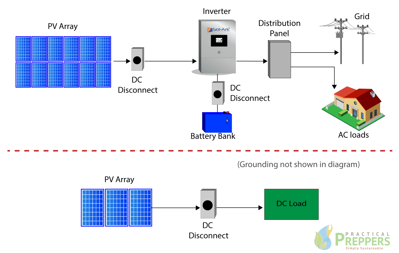
PV Direct - Practical Preppers
etap.com › product › photovoltaic-array-solar-panelPhotovoltaic Array | Solar Panel | Solar Farms | Solar ... - ETAP System planners can represent solar plant as a single machine mathematical model of PV (Photovoltaic) Array to understand the impact of PV penetration in the grid under varying solar and temperature conditions. System dynamic behavior can be studied by changing solar irradiance, tripping the PV plant, simulating system faults at PV connected buses.

Preventing fire hazards and damage in a photovoltaic plant ...
Type 2 Spd Wiring Diagram - U Wiring Connect the SPDs neutral wire white to. The IEC 62196 Type 2 connector is used for charging electric cars mainly within Europe. Type 2 - SPD which can prevent the spread of over-voltages in the electrical installations and protects equipment connected to it. Locate the electrical systems applicable wiring diagram in Section 23.
Yaskawa - Solectria Solar Effective Grounding Tool - Yaskawa ...
Mobile trailer grounding - Victron Community First, safety ground and neutral are connected at ONE place in the system. This provides a fault path that will trip a breaker. Without it, a fault in an AC hot leg could result in dangerous voltages on the the safety ground system including all metal in the system. This connection ("bond") typically occurs at the electrical service entrance.

Solar Panel System Grounding To Earth
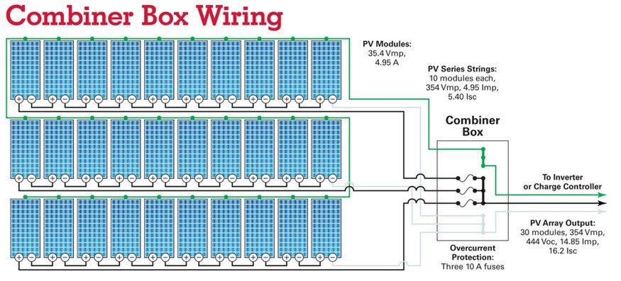
solerusenergy.com › solar-one-line-diagramSolar One Line Diagram 101: For Solar Contractors Sep 24, 2019 · A solar one line diagram (also known as a single line diagram) is an electrical drawing used to design a solar PV installation. A one-page document, it details the main components within the system and uses single lines to show how they are connected. The diagram also includes a summary of the wiring and electrical calculations.
Installation Practices: Keep Your PV System Well-Grounded
zappi v2 installation - myenergi UK This type of battery system uses the solar PV inverter to provide power from the batteries, thus it is not possible to differentiate between solar and battery power when using a CT to measure the AC current from the inverter. Because of this limitation, there are less options for managing the surplus power with this type of battery system.

Do i have too much grounding on my system? - PV & Utility ...
Electrical Wiring Symbols, Meanings and Drawings i want to do solar installation of a 6 bed room, 1 sitting room and a store with solar installation. the house contain 2tvs, 2 fans, 1 fridge and 2 mini bed room musical set system. how much solar panel wattage, batteries and inverter should i use for my house. please help me with guide. thanks.

Protection of Off Grid Solar PV Systems – Off Grid DIY
electrical-engineering-portal.com › academyDesign Course For Solar Energy Systems - EEP Academy Solar PV System design including design of PV modules, inverter, battery, solar charge controller, and MPPT charge controller. Iron core which is responsible for the magnetic flux action; Off-grid system design by using the PVsyst program. Grounding of the PV system and solar kit. On-grid system design by PVsyst program.
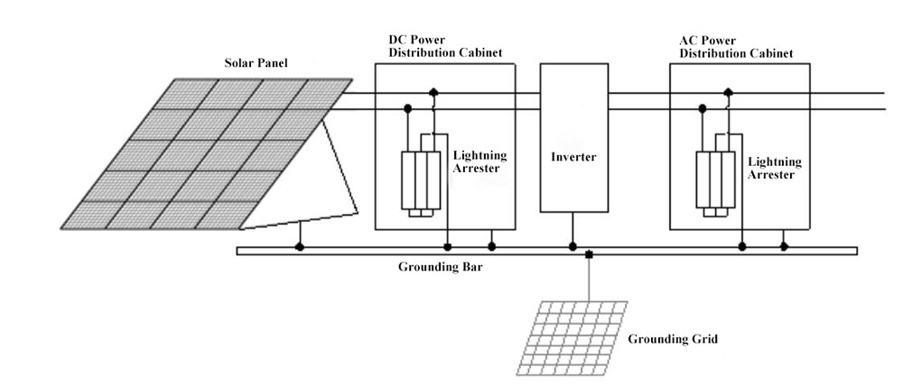
Solar Lightning Protection: PV system grounding and lightning ...
How to troubleshoot a solar system? - Sinovoltaics This article describes how you can troubleshoot a solar system in basic steps. Common issues are zero power and low voltage output.. Troubleshooting a solar (pv) system. Below I will describe basic steps in troubleshooting a PV array. Quality solar panels are built and guaranteed to produce power for 25 years.For that reason, it's most likely that a problem is caused by a defect in system ...
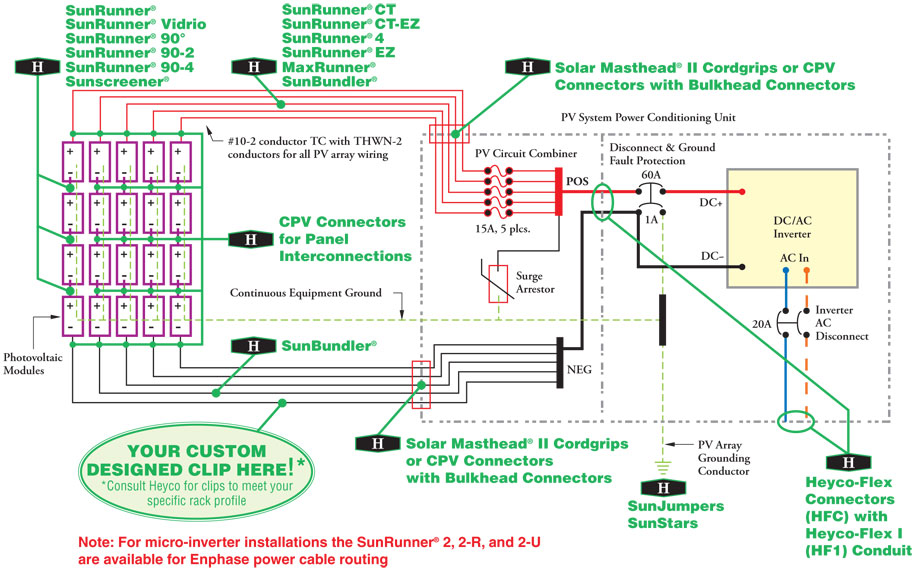
Heyco® Solar Power Components Used in Typical Grid-Tied PV System
› publication › 322738988Design of an Off-Grid Solar PV System for a Rural Shelter Jan 27, 2018 · The goal of the off-grid PV system design is to optimize the most suitable design in order to collect all the available solar energy to satisfy the need for the energy demand at an economically ...
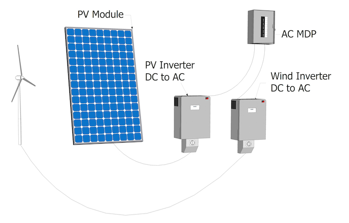
What are Main Components of a Solar PV System? | inverter.com
Solar Lightning Protection: PV system grounding and ... The outer frame of the inverter All the wiring should be grounded. One way of grounding the wiring is by running all the wiring in a metallic conduit and then burying it underground. Another way, if you are running cable trays to run the cables, is by grounding the cable trays along their entire length. The negative side of the power system.
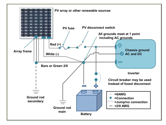
Photovoltaic System Grounding
Grounding and Bonding — New Questions and Answers - IAEI ... It means that if an electrical system has a voltage to ground not more than 150 V (i.e., a typical 120/240 V, single-phase, 3-wire system, or a typical 120/208 V 3 phase, 4-wire system), then the safety objective for solid grounding connection of such electrical system and objective for bonding of metal non-current carrying parts of electrical ...
Solar PV Inspection Checklist
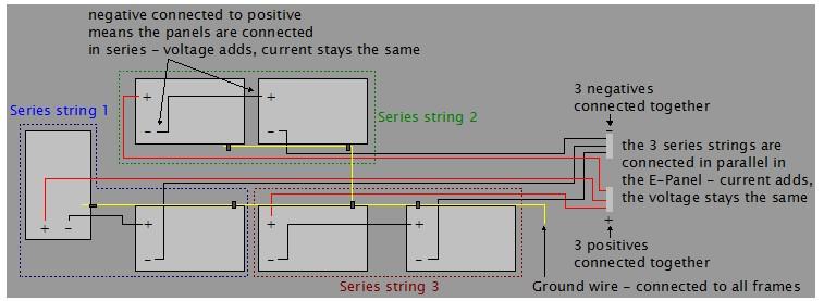
› includes › docsINSPECTING PHOTOVOLTAIC (PV) SYSTEMS FOR CODE-COMPLIANCE Step 2: Electrical Review of PV System (Calculations for Electrical Diagram) • In order for a PV system to be considered for an expedited permit process, the following must apply: 1. PV modules, utility-interactive inverters, and combiner boxes are identified for use in PV systems. 2. The PV array is composed of 4 series strings or less, and ...

Solar Array Grounding System With Lightningproof Grounding ...
Grounding Victron Confusion | DIY Solar Power Forum Apply a single ground connection, preferably close to the battery, to prevent system issues or ground loops. Chassis grounding A separate ground path for the chassis ground is permitted because the chassis is isolated from the positive and the negative terminals. PV array grounding The positive and negative of the PV array should not be grounded.
Battery Cable Wiring for PV Systems | Solar365
2 Pole Switch Wiring Diagram - easywiring 2 Pole 3 Wire Grounding Diagram Unique Nema 6 15p Plug. Diagram double pole isolating switch wiring full version hd quality rackdiagrammer hotelrigelcatania it 2 rotary isolators circuit protection bg electrical china 1000v 32a 4 poles dc isolation pv isolator ac talk electrician forum knightsbridge 230v 415v ip65 world eaton t0 1 i1 svb 3 ...

Solar Photovoltaic Systems ― Part 2 | EC&M
A comparative investigation of the cooling effect of multi ... Figure 4(a) shows a schematic diagram of inlet and incident locations of the PV array panel. ... which can be widely applied to ground-mounted PV systems. IV. CONCLUSION. Section: The present study proposes novel double-layer and triple-layer arrangements for PV panels to reduce the temperature of the PV system. ...
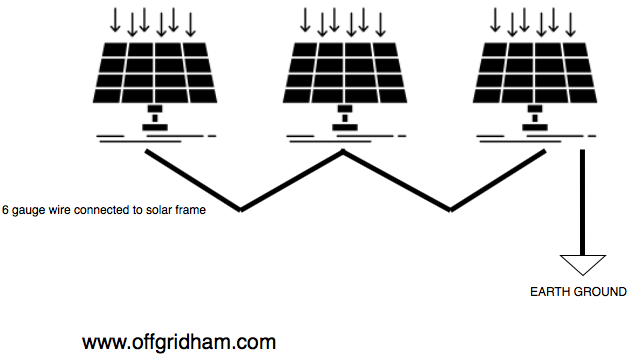
Grounding Your Off Grid System. - Off Grid Ham
Everything You Need to Know About Solar Wires and Cables For small scale solar systems with three-phase inverters, a five-core AC cable is used to connect to the grid. The distribution of the wires is as follows: three live wires for carrying electricity, and one each for ground and natural wire. Meanwhile, use a three-core AC cable for PV systems with single-phase inverter. Final Thoughts

Schematic diagram of (a) grounded and (b) ungrounded PV ...
Analysis and design of solar PV system using Pvsyst ... Finally, the deficit diagram is calculated for the whole year .In addition, the PVSyst simulation software is used to do a performance review of the proposed stand-alone PV system. The simulation results include the total energy provided by the PV array, unused energy, energy supplied to the load, PV conversion efficiency, device losses, output ...

Negative-Grounded vs Ungrounded - Solar Panels - Solar Panels ...
Installation is almost complete! 5 Powerwalls and 400A ... We have had a 7 kW PV system for a while, and with the SMA Secure Power Supply at least we could do basic things while the sun was out. If the power was off, we ran an extension cord out to the PV ground mount and that would keep the refrigerator and computers alive. We are out of power an average of 10 days per year, and it is always a huge pain.
Untitled
› docs › fy16ostiField Guide for Testing Existing Photovoltaic Systems for ... grounding electrode system or is functionally grounded through an overcurrent protection device (OCPD) to a grounding electrode system. Grounding of exposed metal surfaces likely to become energized, also known as equipment grounding, is a requirement for all electrical systems governed by the NEC.
_Solar%20panel%20wiring%20diagram%20-%20large.jpg)
How to wire solar panels | Knowledge Centre | Essentra ...
Solar Photovoltaic (PV) Systems | UpCodes

Bonding and Grounding PV Systems - IAEI Magazine
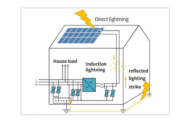
Saving Your Rooftop PV Plant From a Lighting Strike - Saur ...
Photovoltaic System Grounding
Why Commission Solar Photovoltaic (PV) Systems? - Steven ...
Solar PV Inspection Checklist

PV System Ground Fault Troubleshooting | Fluke
PV System Types and Components | AE 868: Commercial Solar ...

How to make lightning protection design of residential PV ...
DIY PV System Installation -- Wiring
Basic Information Required for Photovoltaic Plan Check Submittal

Off-Grid Solar Battery System Bonding and Grounding - Solar ...

Solar Photovoltaic Panels Array Wiring Diagram | Non-Stop ...
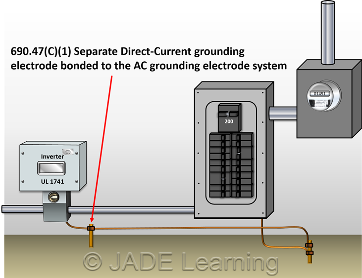
PV Systems: Grounding – JADE Learning

Schematic diagram of (a) grounded and (b) ungrounded PV ...

Grid Tie Solar Power System

Schematic diagram of the underwater grounding electrode array ...
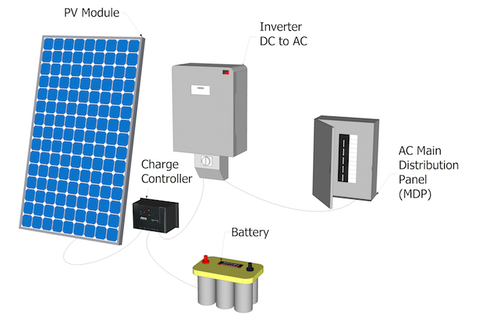
PV System Types and Components | AE 868: Commercial Solar ...

Sample PV Grid-Tied One Line Diagram - Dickson Electric ...
0 Response to "41 Pv System Grounding Diagram"
Post a Comment