37 pod brake controller wiring diagram
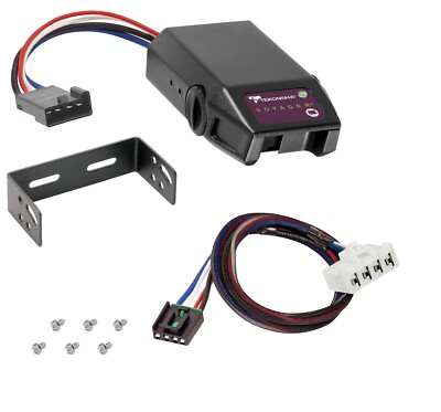
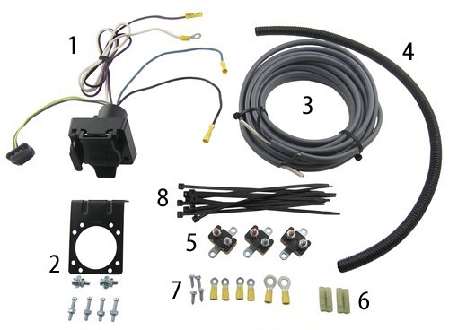
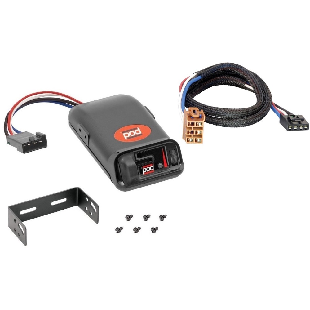
To see our price, add these items to your cart. Add all three to Cart. Choose items to buy together. This item: Tekonsha Pro Series POD Trailer Brake Controller, Timed, 1 to 2 Axles. $36.30. In Stock. Ships from and sold by Amazon.com. FREE Shipping. Tekonsha 3035-P Brake Control Wiring Adapter for Ford. POD Brake Control for 1 & 2 Axle Trailers - #80500. Features Include: Solid State Electronics. Power-on LED Light for a positive tow vehicle to trailer connection. Has a manual over-ride control. Very rugged, and has a easy mount chassis. All Mounting Hardware is included.
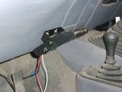
Sep 30, 2021 · Place the pod controller inside the cab of the vehicle near its. Hayman reese electric brake controller wiring diagram wiring diagram is a simplified tolerable pictorial representation of an electrical circuit it shows the components of the circuit as simplified shapes and the capacity and signal contacts between the devices.

Pod brake controller wiring diagram
(See Diagram for Mounting the P3). Wiring Brake Control Your P3 brake control has a unique connector located at the back of the control. This connector allows you two options to wire your brake control. Option 1: Use Pigtail Wiring Harness included. This harness can Brake Control Wiring Kit. P/N 85060 ... Disconnect negative (-) cable before wiring Brake Control Unit. ... Connect wires accordingly to the wiring diagram. To warm trailer brakes, drive a short distance (1/4 mile) at. 45 MPH with manual lever engaged enough to cause trailer braking at a low level. 2. WARNING The ...1 page
Pod brake controller wiring diagram. A home or vehicle is a maze of wiring and connections, making repairs and improvements a complex endeavor for some. Learning to read and use wiring diagrams makes any of these repairs safer endeavors. These simple visual representations all... A brake controller wiring installation kit makes light work! The following diagram is a general guide for wiring common brake controllers into cars. Please ensure you have the correct gauge wire and we do recommend you use an auto-electrician to wire the brake controller into your car. The brake control must be installed with a 12 volt negative ground system. (To install with a positive ground system use Tekonsha ® P/N 3191.) 2. WARNING Reversing BLACK and WHITE wires or improper wiring will damage or destroy brake control. 3. WARNING Be sure to solidly connect all four wires or brake control will not function properly. 4. 1. Connect the supplied pigtail wiring harness into the electrical connection port on the rear of the pod brake controller. Purchase a wiring harness specific to your vehicle application from your vehicle's manufacturer, and plug that harness into the recommended connection portal. Reese has always strived to provide the right trailer towing ...
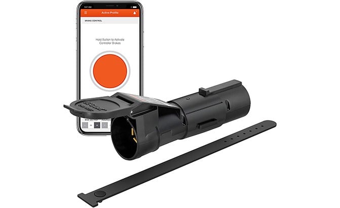
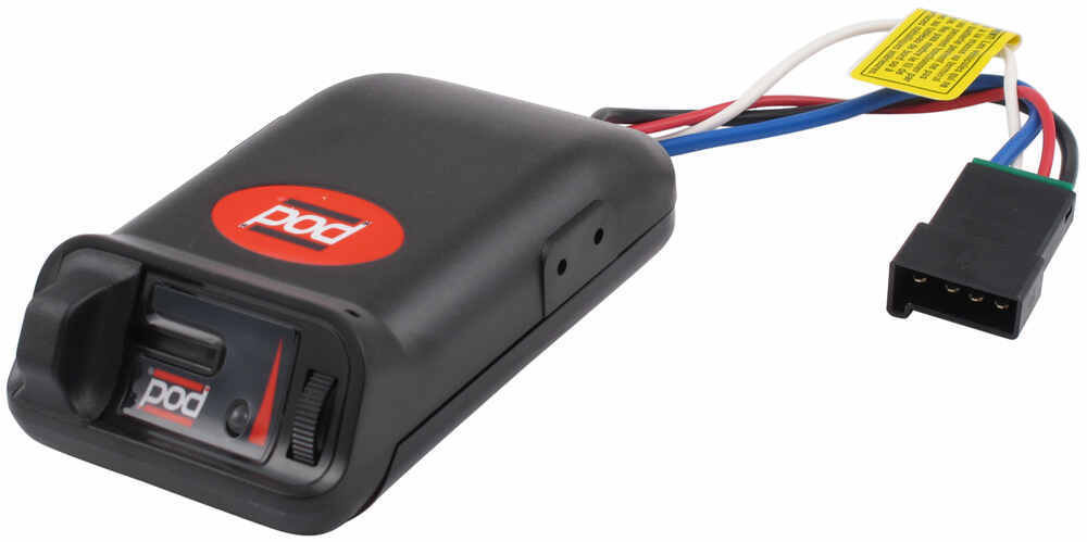
Electric brake controls are designed to apply the brakes of the vehicle's towed trailer. A signal is sent to the trailer's brake magnet or actuator when you apply the tow vehicle's brake pedal. The more power / voltage applied to the electromagnets, the greater the braking force · There are ... The Pod can be mounted in any direction, and its unique design features up-front-easy-access adjustment controls, even when mounted upside down. The Pod is the perfect choice for SUV's with almost vertical dash mounting surfaces. Power-on LED for a positive tow vehicle-to-trailer connection. Up-Front manual mount chassis. Replacement trailer parts to repair and maintain your boat or utility trailer such as bearings, springs, axles, hubs, winches, lights, jacks, coupler, and more at Champion Trailer Parts and Supply. Installing a brake controller involves disconnecting the vehicle battery, mounting the brake controller onto dash and plugging the unit in with a vehicle-specific wiring harness. If your vehicle is not equipped with a plug-and-play harness, you can also splice in wiring for connecting a brake controller. In this guide, we cover step-by-step how to install a brake controller.
Reese Pod Brake Controller Wiring Diagram 16.08.2018 16.08.2018 6 Comments on Reese Pod Brake Controller Wiring Diagram schematron.org Today on this Chevrolet Silverado were going to install part number The Pod (Power on Demand) trailer brake control is your best choice, Accu- Power Pod Brake Reese Pod Brake Controller Manual Pilot Brake ... Solaredge wiring diagram wiring diagram is a simplified okay pictorial representation of an electrical circuit it shows the components of the circuit as simplified shapes and the capacity and signal connections between the devices. The material furnished in this document is believed to be accurate and reliable. Click for more info and reviews of this Tekonsha Trailer Brake Controller:https://www.etrailer.com/Accessories-and-Parts/Tekonsha/3015-P.htmlCheck out some s July 23, 2019 - Yes we can help. To the right there is a picture that has a diagram of how most brake controllers wire up, if you click it you will be able to see an enlarged version of the picture. Below you will find a link to the installation instructions and to wiring instructions for wiring brake controllers.
Trailer Brake Controller Harness (Packaged) SKU #51447 for ...
Pod Electronic Brake Control, for 1 to 2 Axle Trailers . $42.95. Break Away Kits | Brake Control Wiring Harnesses BRAKE CONTROLLER INSTALL KITS: Part # Description. Price . Buy Now: 20505: Wiring Kit for 2 to 4 Brake Control Systems, Includes 25 ft. 12-2 Duplex Wire, 20 Amp Circuit Breaker and Attaching Terminals ...

Tekonsha 3040-P Brake Control Wiring Adapter for Toyota
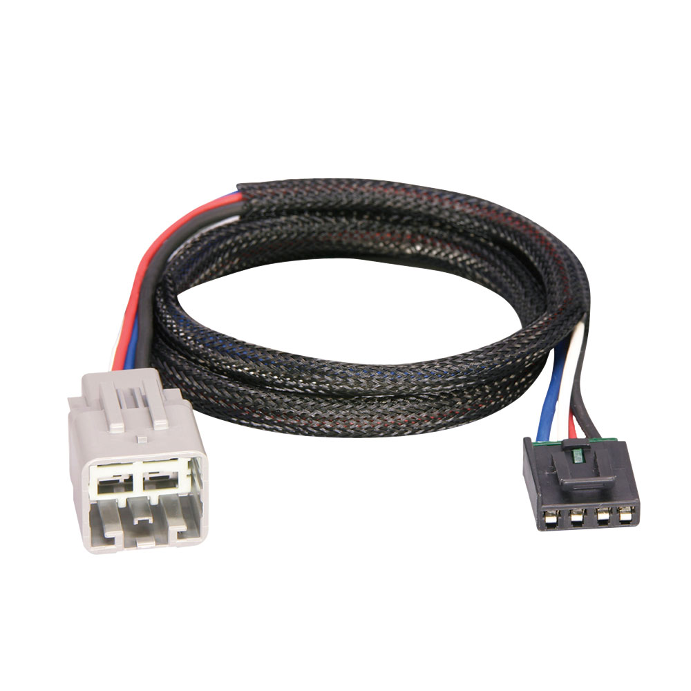
Connect the pigtail-style wiring harness included with the purchase of the Tekonsha brake controller to the back of the in-cab controller unit. Following the wiring diagram included with the controller, run the blue wire through the firewall and to the rear of the vehicle where it will connect to the trailer connector.Brake Controller Wiring ...
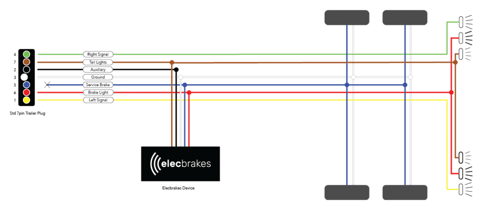
Electric Brake Controller Wiring Diagram : Elecbrakes
The POD® needs to have a complete circuit on the Blue wire to the brake magnets then to ground for the Green LED to come on. Possible Causes: No trailer connected. No power on Black wire of control. Poor or on White wire of control. Open on electric brake wire (Blue wire). Open on the ground wire of the brake circuit. Power back feed on Blue wire.
CONTROLS
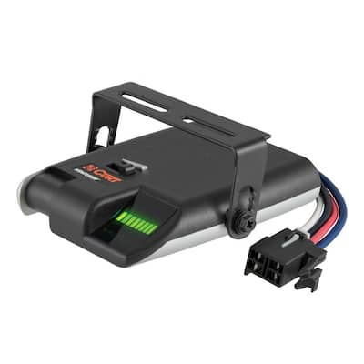
Reese Towpower Pod Brake Controllers. The Reese Towpower timed brake controls generate an output signal that increases over a period of time. These timed-based brake controls apply braking power at a fixed rate that is not proportional to the applied brake pressure.
The Best Trailer Brake Controllers and Why You Need One, 2022 ...
The brake control must be installed with a 12 volt negative ground system. (To install with a positive ground system use Tekonsha ® P/N 3191.) 2. WARNING Reversing BLACK and WHITE wires or improper wiring will damage or destroy brake control. 3. WARNING Be sure to solidly connect all four wires or brake control will not function properly. 4.
Trailer Brake Control - Towing Equipment - Automotive - The ...
Tekonsha Primus Iq Wiring Diagram wiring diagram is a simplified up to standard pictorial representation of an electrical circuit. Brake Control Attachment Locations 1. This connector allows you two options to wire your Brake Control. 6 x 38 Screws C. Primus IQ Trailer Brake Controller Proportional 1 to 3 Axles.

T3 Modular Switchback Signal Pods - Rear – DENALI Electronics
Reese Pod Brake Controller Wiring Diagram 16.08.2018 16.08.2018 6 Comments on Reese Pod Brake Controller Wiring Diagram schematron.org Today on this Chevrolet Silverado were going to install part number The Pod (Power on Demand) trailer brake control is your best choice, Accu-
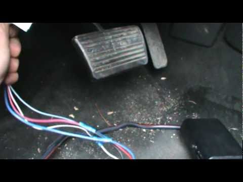
HOW TO INSTALL A TRAILER BRAKE CONTROLLER ON A 2007 CHEVY PICKUP
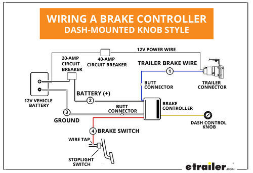
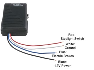
The Reese Pod brake controller should be connected as follows. White - Ground Black - 12 Volt Constant Power Red - Cold Side of the Brake Pedal Switch Blue - Trailer Brake feed to Trailer Brakes If you are correctly wired and you are still experiencing problems, I would start with the following test. Start by disconnecting the blue brake feed ...
Trailer Brake Control for 95-09 Dodge RAM 1500 2500 3500 Wiring Tekonsha Voyager | eBay
Electrical Diagram, Electrical Wiring, Electrical Installation, Pod Camper, Trailer Wiring Diagram,. etrailer.com. 41k followers.
Brake Controller Installation: Starting from Scratch ...
When you tow anything, you must have wiring from the tow vehicle to the trailer that controls lights, brakes, and charge lines.
05-07 Ford F250 F350 F450 F550 Trailer Brake Control Wiring ...
Reese Pod Brake Controller Wiring Diagram 16.08.2018 16.08.2018 6 Comments on Reese Pod Brake Controller Wiring Diagram schematron.org Today on this Chevrolet Silverado were going to install part number The Pod (Power on Demand) trailer brake control is your best choice, Accu- Power Pod Brake Controller, Tekonsha Installation Instructions ...
Towing a Trailer? Let's Talk About Brake Controllers ...
737 400 Air Conditioning System Schematic Diagram . Accu Power Pod Brake Controller . Acdelco 15926102 Gm Original Equipment Trailer Brake Control Switch Assembly . Reese Pod Wiring Diagram Wiring Diagram . Endless Brake Pads Set Circuit Compound Cc35 Type E N84m Alcon Ap Racing Caliper Cp6060 6065 6075 6080 Rcp072
Brake Controller Installation: Starting from Scratch ...
Save loads of money on labor by installing your new electric brake controller for your trailer. The electric brake controller will improve stopping performance and safety. It will also reduce the brake wear on your vehicle when towing.
Brake Controller Installation: Starting from Scratch ...
Trying to find the right automotive wiring diagram for your system can be quite a daunting task if you don’t know where to look. Luckily, there are some places that may have just what you need. Here’s where to start. Before you search for a...
Oem Trailer Brake Controller | Page 3 | Chevy Colorado & GMC ...
November 2, 2021 - Electric Brake Controller Wiring Diagram. Wiring Diagram. Auxiliary connection is optional, it may be connected to any 12v to 24v constant power source or left unconnected. Break away systems may be added to the service brake circuit. Elecbrakes is designed to operate 1 to 2 braked axles. Get.
Factory brake controller install and program! | Ford Transit ...
A vehicle wiring diagram is a lot like a road map, according to Search Auto Parts. Wiring diagrams are laid out similar to a road map because the diagrams show how each major electrical system, individual circuit and sub-system connects, th...
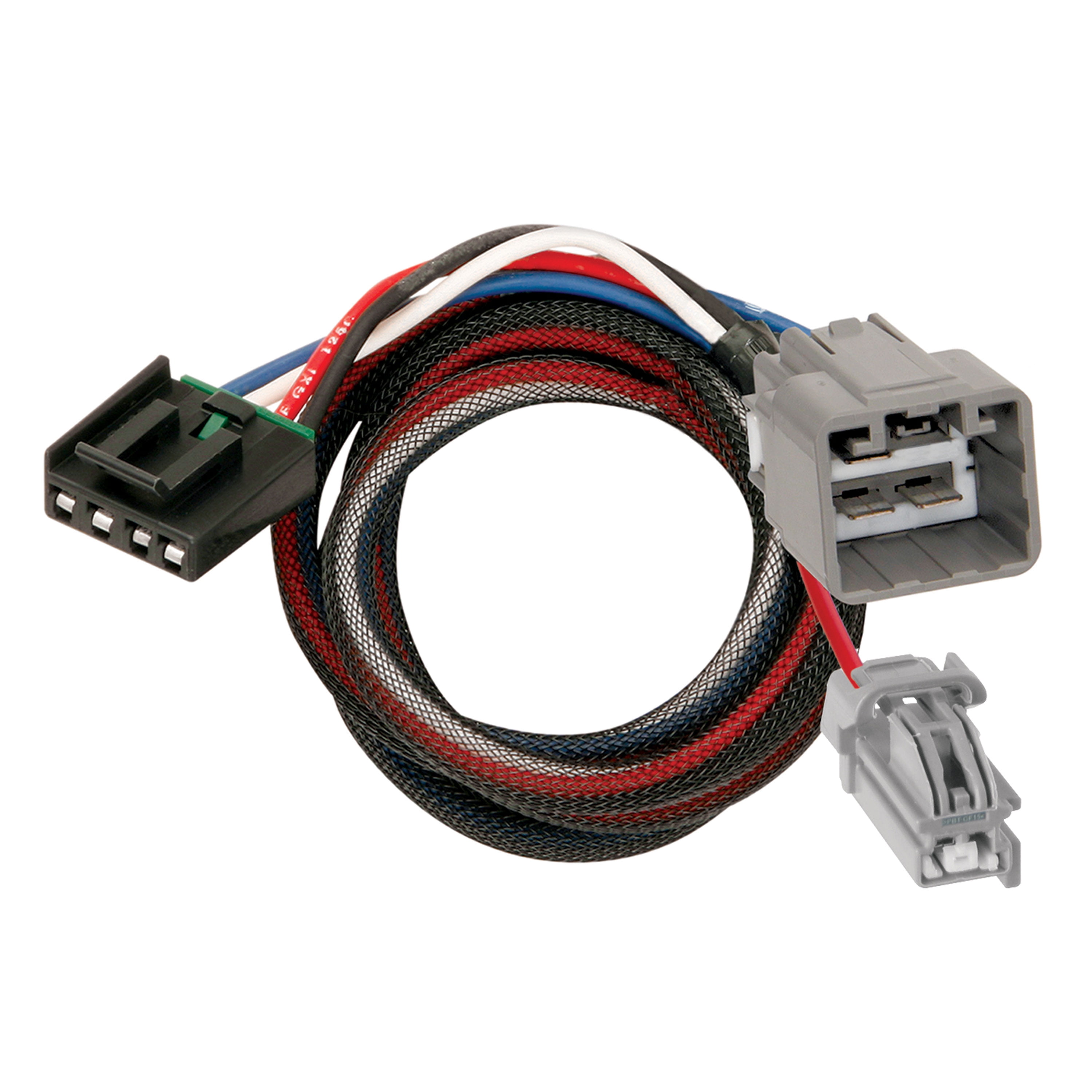
Tekonsha 3023-P Trailer Brake Control Wiring Harness - 2 Plugs, Dodge
Oct 14, 2021 · Pod Point are UK leaders in electric vehicle charging with innovative solutions for homes workplaces and commercial organisations. Pod Brake Controller Wiring Diagram Point R 177 Challenger Radio. Guitar POD unit Amplifier CDMP3 input with 14 dummy plug in the instrument input 2 If your amplifier has an effects loop ie.

The 7 Best Brake Controllers For RVs | RV Care | Bayside RV
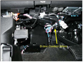
Brake Controller Wiring Schematic for a 2010 Chevy Silverado. Question: We need the wiring schematics for a 2010 silverado. asked by: Dean. 0. Expert Reply: The 2010 Chevy Silverado will have a wire bundle tucked up under the dash, to the left of the steering column, held together with a white tag. The tag should also have the wire functions on ...

Tekonsha | Timed Controllers
Presented by Hayman Reese technical towing expert Gary Gardiner, watch the typical installation process of Hayman Reese Brake Controllers, including end-to-e...

Reese Towpower | 74377 | POD® Trailer Brake Controller, Timed ...
23. jul. 2019 ... I have attached the installation instructions for this particular controller along with a general brake controller wiring diagram that you might ...

Electric Brake Controllers & Wiring | Trailerpartsdepot.Com
The Reese POD brake controller is an especially attractive electronic brake control when your installation options are limited. The Reese POD can be mounted in any direction, and its unique design features "up-front easy- access" adjustment controls, even when mounted upside down. The POD is the perfect choice for SUVs with almost vertical dash ...
Troubleshooting Brake Controller Installations | etrailer.com
Brake Controllers. Brake Control Installation Instructions and Manuals: ... Brake Control Optional Wiring Harness - 12" Length. $11.00. Prev Next.

Reese Towpower | 7437711 | POD® Trailer Brake Controller ...
Instructions for Pod® Brake Control READ THIS FIRST: Read and follow all instructions carefully before installing or operating the Brake Control. Keep these instructions with the Brake Control for future reference. D B C A Installation Guide A. Mounting Bracket B. #6 x 3/8" Screws C. Mounting Holes A C B P/N 7760 REV G NOTE: 1.
Hidden Trailer Brake Controller install (pics) | Tacoma World
Bumper-to-bumper overview of the brake controller setup on my truck. This is largely based on Eric the Car Guy's installation video @ https://youtu.be/N5PjlK...
Tekonsha PowerTrac Electronic Brake Controller - 1 to 2 Axles ...
Reese Pod Brake Controller Wiring Diagram 16.08.2018 16.08.2018 6 Comments on Reese Pod Brake Controller Wiring Diagram schematron.org Today on this Chevrolet Silverado were going to install part number The Pod (Power on Demand) trailer brake control is your best choice, Accu- Power Pod Brake
Factory" 7pin Trailer Harness Installation | Tacoma World
TRAILER BRAKE CONTROLLERS The Electric Trailer Brake Controller 03 1. Installation 03 2. the brakes from either the foot brake or the manual button on the. Accu-Power Pod Brake Controller. Tekonsha (Part Number:80500) Up-Front manual mount chassis.

Tekonsha | Timed Controllers
Black wire connects to 12VDC positive White wire connects to battery negative Blue - Brake controller output to trailer electric brakes. Improper connection of Positive and Negative wires MAY damage or destroy brake controller. Confirm wiring diagram instructions with your Brake Control ...

Trailer Brake Controller Harness (Packaged) SKU #51447 for ...
Trailer Parts Superstore offers this DRAW-TITE wiring diagram for general reference only. Consult your tow vehicle owners manual for specific wiring information.
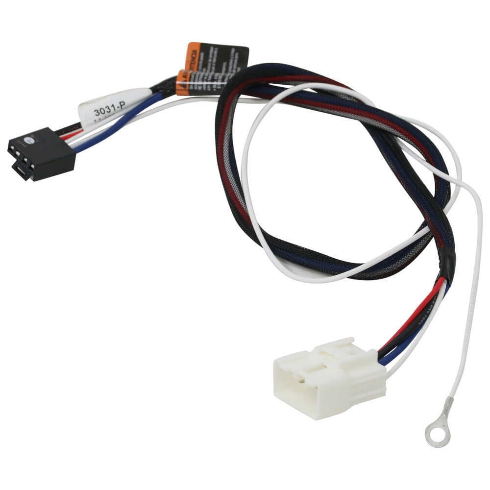
Tekonsha 3031-P Brake Control Wiring Adapter - 2-Plug, Toyota Tacoma 2015-2018
Connect the supplied pigtail wiring ... the pod brake controller. Purchase a wiring harness specific to your vehicle application from your vehicle's manufacturer, and plug that harness into the recommended connection portal. Place the pod controller inside the cab of the vehicle near its final mounting location. ... Connect the coinciding wires from the ...
Trailer Brake Control for 99-02 Chevy Silverado 1500 2500 ...
The following list was printed from the Tekonsha website on Tuesday, January 18, 2022 at 8:52 PM
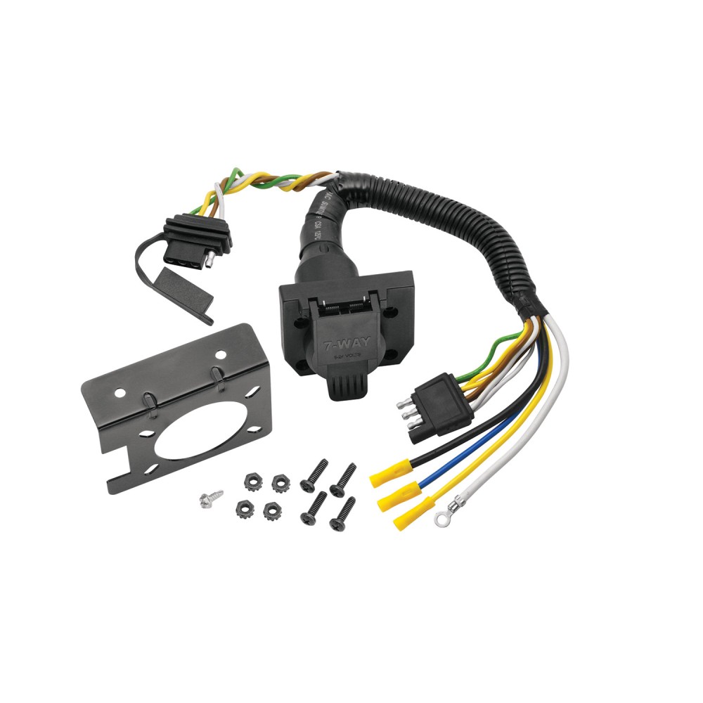
04-10 Toyota Sienna 7 Way RV Trailer Wiring Plug Prong Pin ...
Connect to the brake controller and route the black and blue wires. Find the blue wire that comes off of your electronic brake controller. Attach the blue wire that came with your 7-wire plug to this blue wire. Locate the rubber grommet that surrounds the interior wiring harness where it feeds through the firewall.

Reese Towpower | 74377 | POD® Trailer Brake Controller, Timed ...
Aug 16, 2018 · Reese Pod Brake Controller Wiring Diagram 16.08.2018 16.08.2018 6 Comments on Reese Pod Brake Controller Wiring Diagram schematron.org Today on this Chevrolet Silverado were going to install part number The Pod (Power on Demand) trailer brake control is your best choice, Accu- Power Pod Brake Controller, Tekonsha Installation Instructions ...
How to Install the Tekonsha PowerTrac Electronic Brake ...
Roadmaster tow bar wiring rm 154. Robk the redarc uses the same protocol of wiring as does a tekonsha.

REESE Towpower 8507111 Brakeman IV Digital Brake Control, Small Compact Design
@JonG I have a 2020 Dodge durango. I have to hard wire my brake controller in. On my wiring harness for the brake it has 2 12 gauge wires black and blue and 16 gauge red and white. On your wiring diagram it says to use 12 gauge or higher. Should I match the wires according to my wiring harness or use 12 gauge on all?

Reese Towpower 7805011 Brake Control Wiring Harness
To warm trailer brakes, drive a short distance (1/4 mile) at. 45 MPH with manual lever engaged enough to cause trailer braking at a low level. 2. WARNING The ...1 page

Details about Trailer Brake controller 7437711 Reese Towpower POD NIB
Brake Control Wiring Kit. P/N 85060 ... Disconnect negative (-) cable before wiring Brake Control Unit. ... Connect wires accordingly to the wiring diagram.
Brake Controller Connection | Ford Transit USA Forum
(See Diagram for Mounting the P3). Wiring Brake Control Your P3 brake control has a unique connector located at the back of the control. This connector allows you two options to wire your brake control. Option 1: Use Pigtail Wiring Harness included. This harness can
0 Response to "37 pod brake controller wiring diagram"
Post a Comment