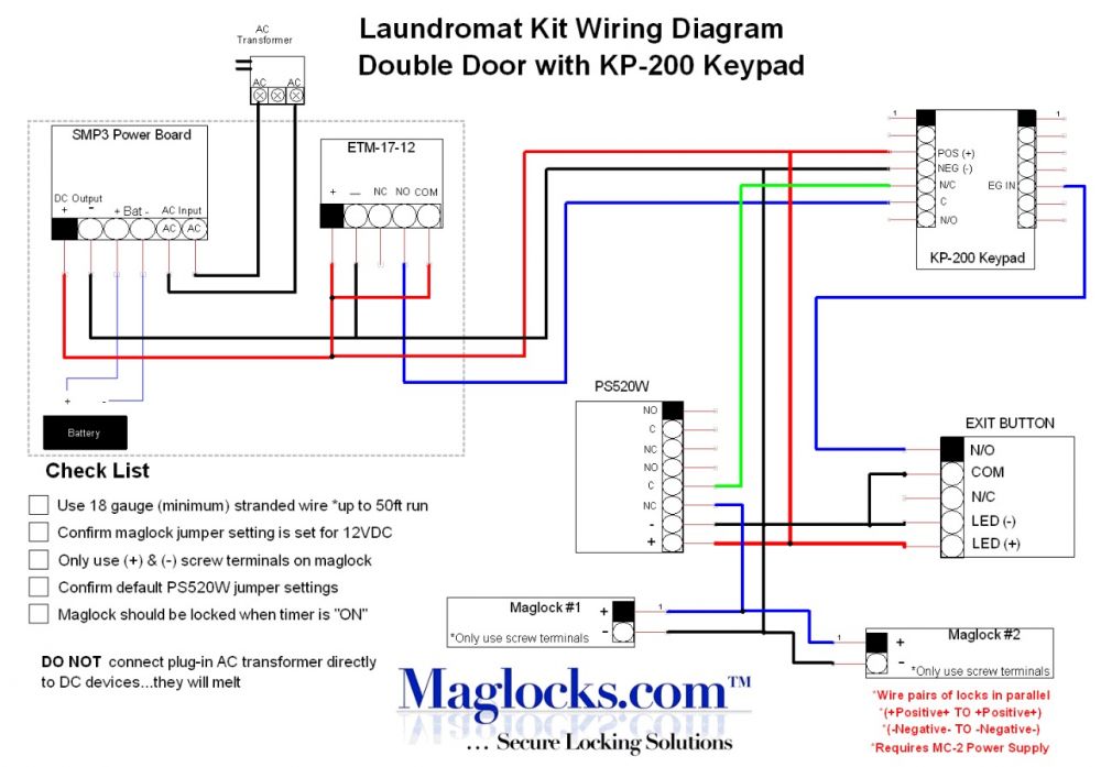
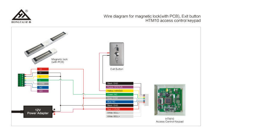
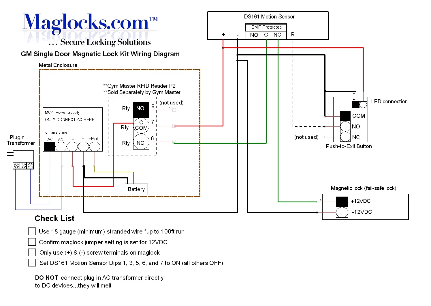
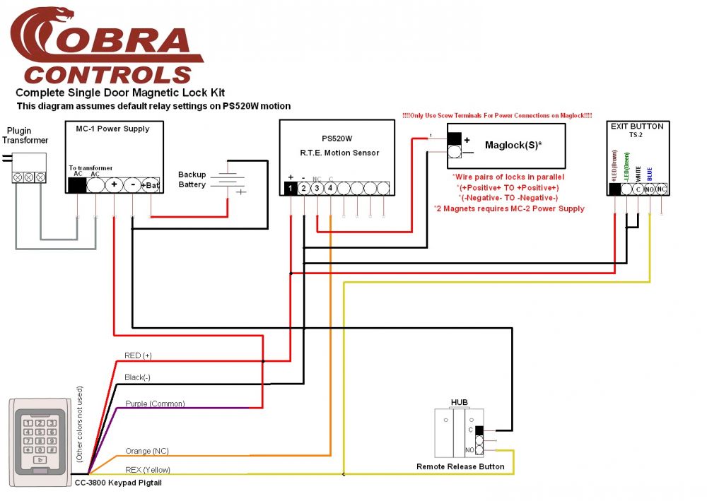
37 Mag Lock Wiring Diagram
Locknetics Maglock Wiring Diagram Collection - Wiring ... locknetics maglock wiring diagram - What is a Wiring Diagram? A wiring diagram is an easy visual representation with the physical connections and physical layout of the electrical system or circuit. It shows how a electrical wires are interconnected which enable it to also show where fixtures and components might be connected to the system. KAS Smart Locking Solutions Some of our electronic lock systems use RFID-programmed cards. Others incorporate keypads, fingerprint scanners Bluetooth or wifi technology. Today, a key can be a PIN code, a fingerprint or even a mobile device. There’s no need to carry around extra keys or key cards – or to deal with what happens if you, your guests, residents or employees lose them. Durability. They provide …
Doorbell Wiring Diagrams - New House Checklist 01.10.2019 · Depending on the layout of your home and location of doorbell components, choose if individual or bundled wires work better (ref. single doorbell button wiring diagram). WARNING: Electrical Hazard. Before beginning work, turn power off …
Mag lock wiring diagram
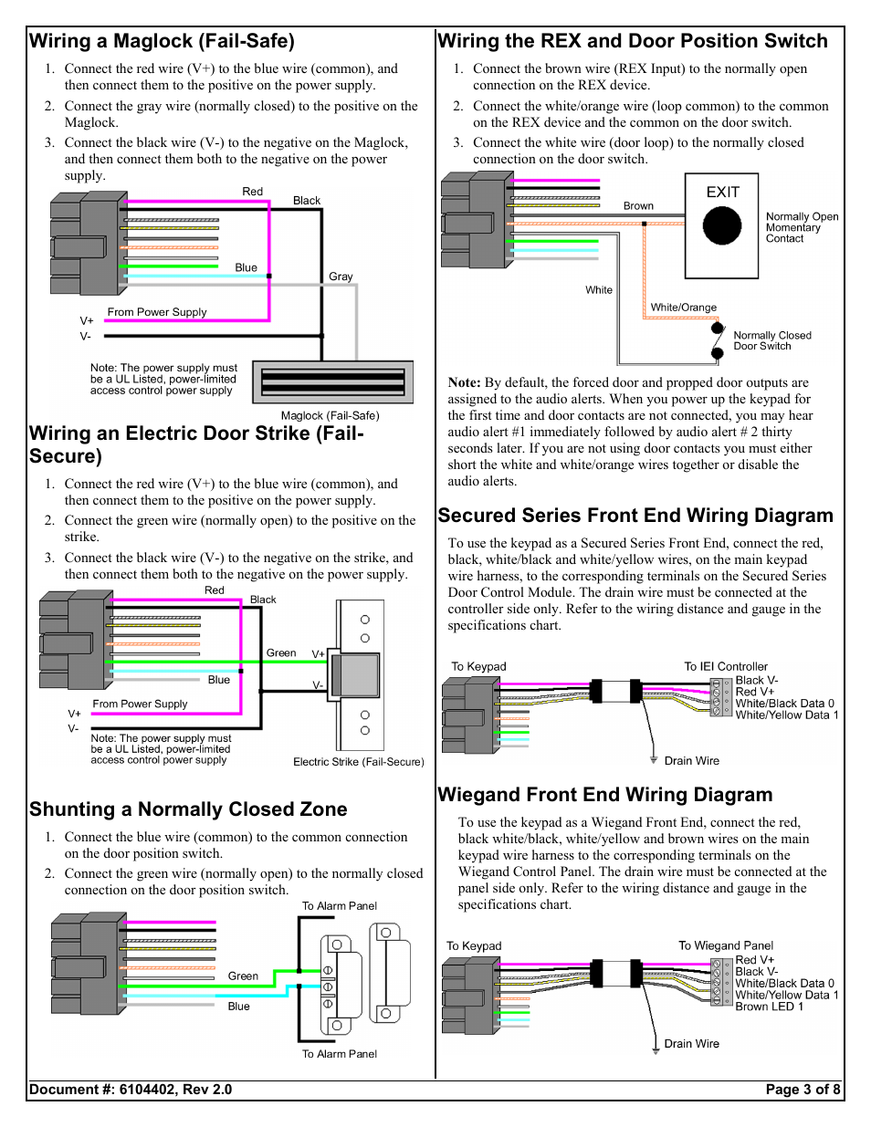
PDF - WIRING INSTRUCTIONS— fail secure strike with one button - WIRING INSTRUCTIONS— Magnetic lock or fail safe strike with button, keypad, maintained button and remote receiver. wired in series Power Supply for fail safe strikes and magnetic locks should be DC. If this is not available you may use an AC power source and wire inline a "Full Wave Bridge" rectifier. This will conver t the AC to DC. Wiring Diagram Of Providing Power To A Fail Safe Maglock ... 1 SPDT voltage output . The SDC ACM-1 Access Control Module is an magnetic lock or electric strike. . (for two door or tamdem applications). The next step is to have a 'fail safe' method of cutting the power to the lock to ensure the Where access control equipment is fitted to a fire escape door which includes an Wiring Break glass units and fire alarm interfaces The FIB provides a switching ... Maglock Wiring Diagram Wiring Diagram for Mag-Lock w/ Push Buttons Wiring Diagram - Biometric & Push Button. If this is not available you may use an AC power source and wire inline a "Full DC output, or you can damage the magnetic lock or fail safe strike. It is essential that the surfaces of the armature and the magnetic lock seat perfectly to one Maglock. Mounting.
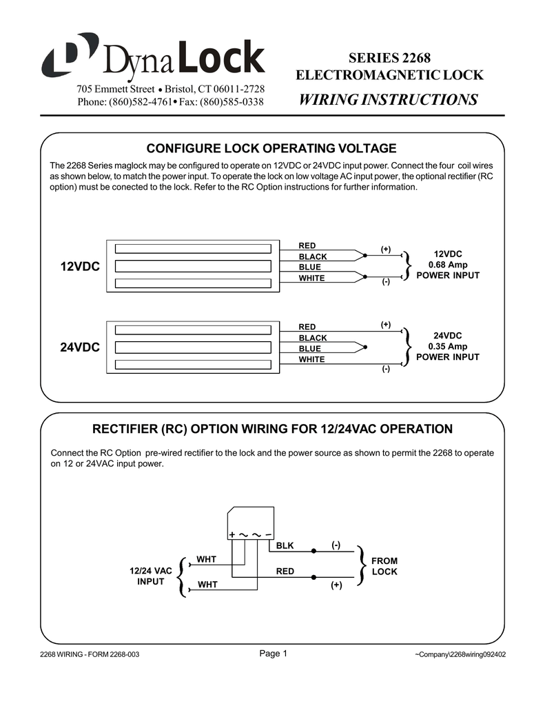
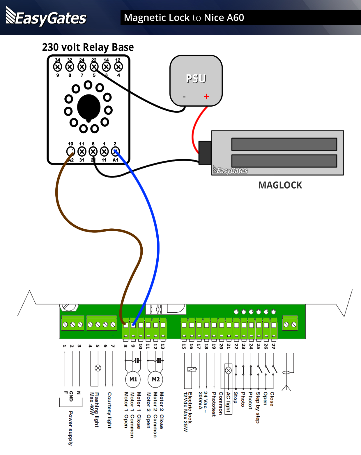
Mag lock wiring diagram. MAG LOCK WIRING DIAGRAMS - Allegion " MAG LOCK WIRING DIAGRAMS ... Resolution: For additional details and a wiring diagram see the MA service manual page on electrical requirements here. What are the Falcon T lock electrical requirements? Resolution: As of June 2011 the electrified T locks can support 12 or 24 Volts. You do not need to specify 12 or 24 when ordering since the ... Magnetic Lock Wiring Diagram - Wiring View and Schematics ... Dahuawiki. How to wire with a mag lock basic installation of access control وضع باب مراقبة 350lb مخفي قفل single door laundromat magnetic magloc880 880lb wireless release china 350kg electromagnetic wiring diagram pdf weatherproof 1100lb maglock rex device cables and pi manufacture on front arduino help system hubpages avoid common cable mistakes dahuawiki em series euro ... PDF Magnalock Models M32, M62 and M82b Installation ... red wire receives +12VDC or +24VDC, and the black wire, 0 Volts (negative). If the lock is connected with reverse polarity, it will not operate. The M32, M62 and M82B Magnalocks are auto sensing dual voltage locks. The Magnalock circuit design will automatically select the proper operational conditions for the applied voltage. PDF Basic Wiring Diagrams IP Bridge, RC-03, and RC-04 - Isonas Magnetic Lock NC Isonas In Rush Suppressor +12VDC 12VDC Com NO Exit Button Such as Securitron EEB2 Note: At a minimum voltage and D0/D1 must be ... Refer to wiring diagrams for details. Interior Button Shown here as electric strike powered by 12vdc from the RC-03. Verify power consumption and use
M400 Series Electromagnetic Lock - Allegion M400 Series electromagnetic locks or "mag locks" are used as part of an electronic security solution usually combined with push bars, request-to-exit devices and credential readers. They are an easy-to-install alternative to electric strike or electric lock products with a bayonet mounting design that eliminates the need to hold the lock ... Wiring Maglock (Electromagnetic Door Lock), Push Button ... Wiring Diagram Electromagnetic Door Lock, EM Lock, Push Button, Power Supply 12v, Carane ngonek kunci magnet. Zkteco F17 Wiring Diagram - Wiring Diagram Zkteco F17 Wiring Diagram. By facybulka Posted on December 14, 2017 8 views. It is ip65 rated which enables it to be resistant from water dust and other outside damages. Complete setup and programming can be done via keypads and embedded firmwareaudio visual indication for acceptance and rejection of validinvalid fingerprints. Instruction Manuals | Napco Security Technologies - Alarm Lock Keyless doors locks can improve the security of your home or business. Visit AlarmLock.com for the latest in high security locks for hotels. For more information, visit us online or call 1 …
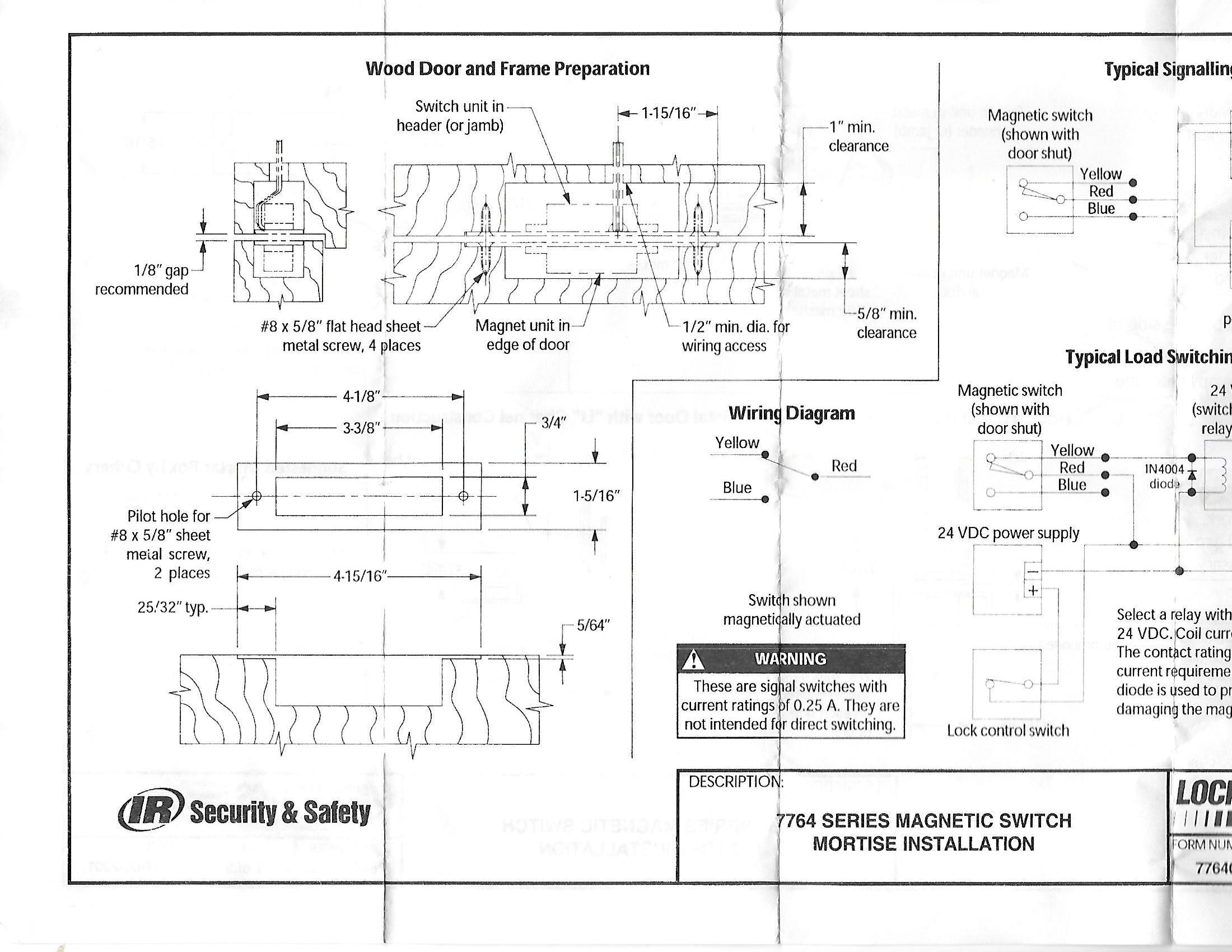
Locknetics Maglock Wiring Diagram Locknetics Maglock Wiring Diagram This manual covers the complete installation and wiring instructions for the following. GF . Make final wiring connections (see Wiring Diagram: on page LOCKNETICS. M I MN MORTISED MAGNETIC LOCK. INSTALLATION AND WIRING INSTRUCTIONS. Birch Street, Forestville, CT. Wiring should be protected by conduit. Access Control and Fire Alarm System Integration - Kintronics 08.08.2017 · The wiring used in these examples should conform to the fire codes. Here are the examples of how to control your access control system using direct wiring from the fire alarm control box. Using a Relay to Control Power to Electric Lock. In this example, the fire alarm provides a ground signal to a relay that controls power to all the locks. In this configuration, the … Installation Schematics and Wiring Diagram ... - maglocks The following reference sections provide installation documents and wiring diagram schematics for maglocks door access system components, kits and equipment. If you have additional questions regarding hardware or software requirements or the wiring diagram set-up, we are available to help. Demystifying Holley Terminator and Sniper Ignition Hookup 01.02.2017 · By that I mean originally I wired for a standard points system and since moved to a mag distributor and want the sniper to control timing. There is no information about color and placement that I can find. I have been on infinite hold trying to get the information and gave up. So I decided to post on the forum thinking that they would chime in but instead I got the usual 'call …
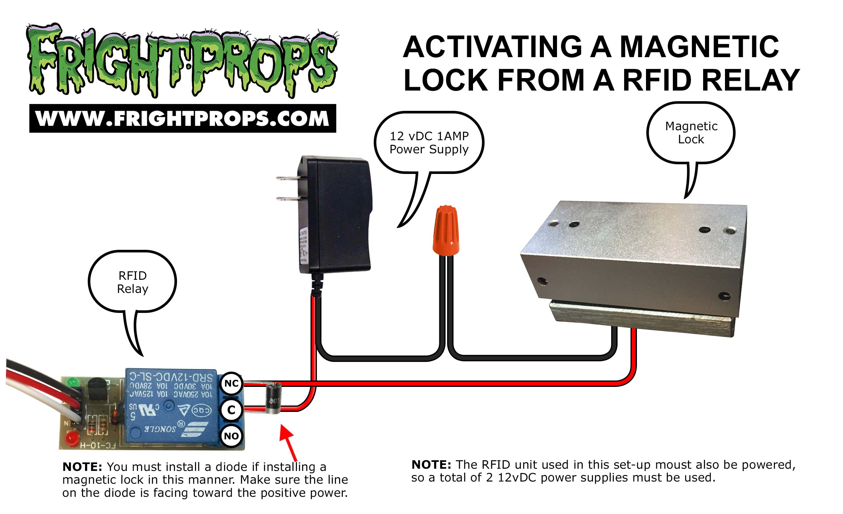
Basic Magnetic Door Lock System - HubPages Basic mag wiring diagram Wiring the Electromagnetic Locking System In the simple diagram above, you can see that the electricity travels in an unbroken loop.
maglock installation diagram maglock installation diagram. navy blue blouse near me / February 11, 2022 February 11, 2022 / csun career center jobs ...
CCTV Installation and Wiring Options 12.05.2018 · CCTV Installation and Wiring Options . Today there are a lot of options when it comes to choosing a quality CCTV security system. You may decide to go with a traditional analog system, HD-SDI, HD-CVI or even an IP network based security products.. One thing all of these options have in common is you will probably have to run some sort wire to the cameras.
PDF Magnetic Lock Installation Instructions MAGNETIC LOCK WIRING INSTRUCTIONS MODELS 600S, 600L, 600D, 1200S, 1200L To remove the header plate, it may be necessary to remove the wiring compartment screw. A long wiring compartment screw can be used to increase security by limiting access to the header plate mounting
Monitored Maglock Wiring Diagram - Wiring Diagram Mx86 Mag Lock Wiring Diagram Knight Fire Security. Em40ds Standard Double Magnet Monitored With Door Status Manualzz. China Single Door 800lbs Electric Gate Lock Em Mag Timer Led Light Monitored Is Optional On Global Sources Magnetic Electronic Maglock. Magnalock Models M32 M62 And M82b Installation Instructions.
PDF Detex Wiring Diagram magnetic lock(s) release(s) allowing egress through gate. Shunting the alarm and rearming the delayed egress system requires use of authorized key switch located adjacent to gate. When activated, the ˜re alarm system will send a signal to deactivate the delayed egress system, allowing immediate egress. The local alarm will sound until reset.
PDF Electromagnetic Lock Installation Instruction (Waterproof ... electromagnetic lock and the armature plate has to be completely attached; otherwise, the reed, which located in side the electromagnetic lock, will not be detected. It will result an incorrect output message for the bond sensor. Minimum Wire Gauge for12VDC Minimum Wire Gauge for24VDC Be aware that it is better to install the electromagnet lock ...
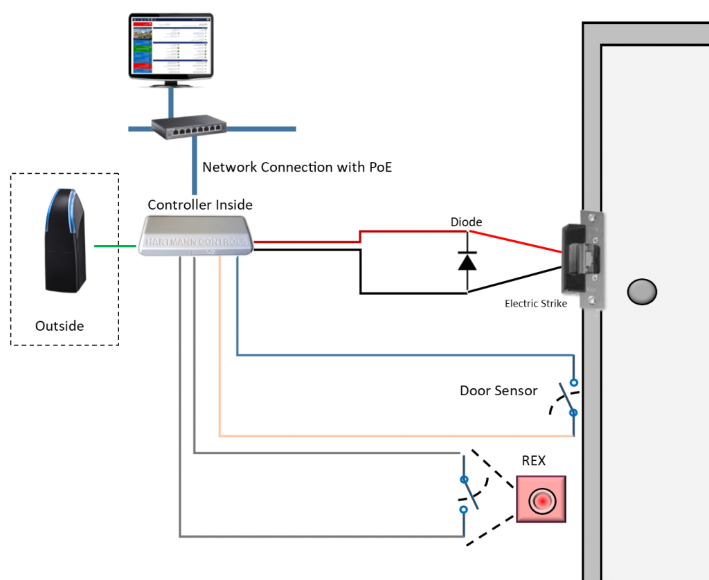
Common wiring diagrams - Allegion mag lock wiring diagrams . chexit wiring diagram . lever locks for fire doors . emergency release tool . two single doors with panic bars . two single doors with panic bars . push button release electric strike . HOT ELECTRIC TRIM . is there an rga form? ...
Basic Wiring for Motor Contol - Eaton is a typical wiring diagram for a three-phase mag-netic starter. Figure 1. Typical Wiring Diagram Line diagrams show circuits of the operation of the controller. Line diagrams, also called “schematic” or “elementary” dia-grams, show the circuits which form the basic operation of the controller. They do not indicate the physical relation-ships of the various components in the …
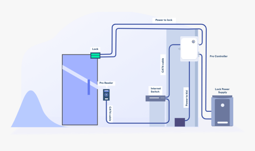
Access Control Cables and Wiring Diagram | Kisi Magnetic Lock Wiring Diagram. Much like the door access control system diagram above, the mag lock wiring diagram relies on a few simple basics: electricity supply, switches, and, of course, locks. Magnetic locks, also referred to as mag locks or maglocks for short, rely on a constant flow of electricity to stay sealed. When that power is cut, the magnet essentially turns …
Magnetic Lock Kit Wiring Instructions - YouTube You can purchase our magnetic lock kits at video shows detailed instructions on how...

Visionis VIS-7000 Indoor Green Square Request to Exit Button for Door Access Control with LED Light, NC, C and NO Outputs
Maglock Wiring Diagram - schematron.org Wiring Diagram for Mag-Lock w/ Push Buttons Wiring Diagram - Biometric & Push Button. It is essential that the surfaces of the armature and the magnetic lock seat perfectly to one Maglock. Mounting. Bracket. Weld to fence post. (Typical connection). Common wiring diagrams
PDF Installation Instructions E600 Series Magnetic Lock The E600 Series magnetic lock is mounted to the underside of the header, on the stop side of the door. An inswing mounting kit (optional) can be used when mounting on the hinge side of the door. P:\INSTALLATION INST\Electromagnetic Locks\EXCEL\INST-E600.vsd REV A3 05-18 Page 1 Any suggestions or comments to this instruction or ...
Door Lock Wiring Diagram - U Wiring Magnetic Lock Wiring Diagram. This is the wiring for a dimmer in a 4 way circuit. 30 Amp Rv Twist Lock Plug Wiring Diagram. Larger diagram In this example the manual labeled the blue wire leaving the 6-pin connector. The following common wiring diagrams are available. Lg Double Door Refrigerator Wiring Diagram.
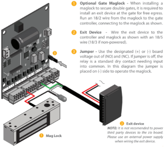
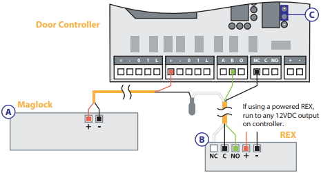
Wiring a Maglock with a REX Device - ProdataKey, Inc. When wiring a fail-safe lock, a closed (series) circuit must be maintained to continuously power the lock. Connect the positive (+) lead of the power supply to C (Common) on the REX. Connect the REX's NC (Normally Closed) to C (Common) on the circuit's hardware component (motion sensor, maglock, or reader).
Wiring and Configuring a REX Device - ProdataKey, Inc. If the jumper is off, the relay is a standard dry contact needing input into common (C). In the above diagram, the jumper is placed on the (-) side to operate the maglock. Connect a wire from the REX negative (V-) to the negative of the door controller terminal block. Connect a wire from the REX positive (V+) to the positive of the door ...
1967-1968 Camaro - Classic Instruments An external adapter such as an MSD Pro Mag Tach Converter #8132 may be required. ACCEL IGNITION COILS . Signal comes from the negative side of the coil. CAUTION! Some Accel ignition coils require the tach signal wire to be connected to the “+” terminal on the coil! PLEASE carefully read Accel’s instructions before connecting ignition coil. MALLORY IGNITION . Signal …
> Magnetic Lock Setup Guide Figure 6: Unscrew the access panel on the magnetic lock using the Phillips-head screwdriver.: Figure 7: The inside of the access panel includes a diagram with labels.: Step 4: Insert Interconnector Wires into Magnetic Lock. Refer to the interconnector manual (usually same manual as access control panel, since they are often packaged together) and note which wires should be connected to ...
3 Ways to Hotwire a Car - wikiHow 10.12.2021 · Break the steering lock. You've got the car started and you're ready to get your engine pumping and let your car loose, right? Wrong. While your car is running, the steering column is probably locked at this point, meaning that you'll have to break it to be able to steer, unless you want to drive straight off a cliff or something. On some models, all you'll need to do …
Maglock Wiring Diagram Wiring Diagram for Mag-Lock w/ Push Buttons Wiring Diagram - Biometric & Push Button. If this is not available you may use an AC power source and wire inline a "Full DC output, or you can damage the magnetic lock or fail safe strike. It is essential that the surfaces of the armature and the magnetic lock seat perfectly to one Maglock. Mounting.
Wiring Diagram Of Providing Power To A Fail Safe Maglock ... 1 SPDT voltage output . The SDC ACM-1 Access Control Module is an magnetic lock or electric strike. . (for two door or tamdem applications). The next step is to have a 'fail safe' method of cutting the power to the lock to ensure the Where access control equipment is fitted to a fire escape door which includes an Wiring Break glass units and fire alarm interfaces The FIB provides a switching ...
PDF - WIRING INSTRUCTIONS— fail secure strike with one button - WIRING INSTRUCTIONS— Magnetic lock or fail safe strike with button, keypad, maintained button and remote receiver. wired in series Power Supply for fail safe strikes and magnetic locks should be DC. If this is not available you may use an AC power source and wire inline a "Full Wave Bridge" rectifier. This will conver t the AC to DC.









0 Response to "37 Mag Lock Wiring Diagram"
Post a Comment