40 dsl pots splitter wiring diagram
Here is the connection diagram: Existing wiring. NID ***** inside wiring to phone jacks. New wiring. NID ***** POTS/DSL Splitter **** "VOICE". Installing the DSL Splitter Near the NID. In the diagrams on this page, If your DSL service provider installs a splitter in or near your NID, they will probably also . The Tecumseh carburetor diagram provided by us is a detailed description of the inside of the carburetor.Ethernet Splitter Wiring Diagram - Nov 12, · Adsl modem wiring further dsl pots splitter wiring diagram along with null modem cable wiring diagram furthermore dsl splitter wiring diagram as well as parts and service manual for charmglow further how it works as well as two wireless works on same sub also wifi modem circuit diagram along.
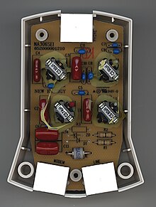
The ADSL POTS splitter is simply a series of coupled inductors and parallel capacitors forming a low pass filter that attenuates the higher frequency ADSL data and permits only the voice frequencies to reach the telephone. The series inductor shows high impedance to high freuqencies, so the ADSL signals on the line are not attenuated.

Dsl pots splitter wiring diagram
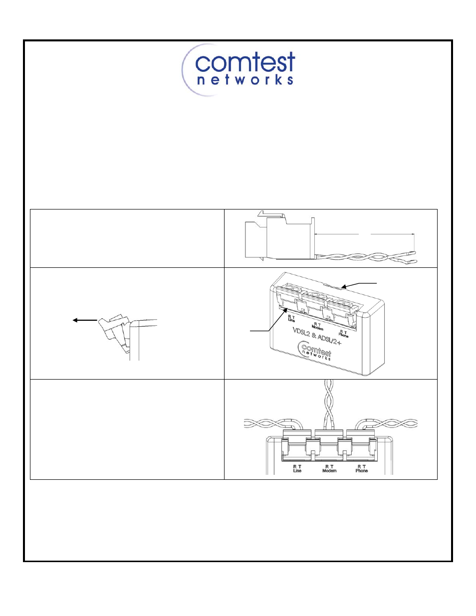
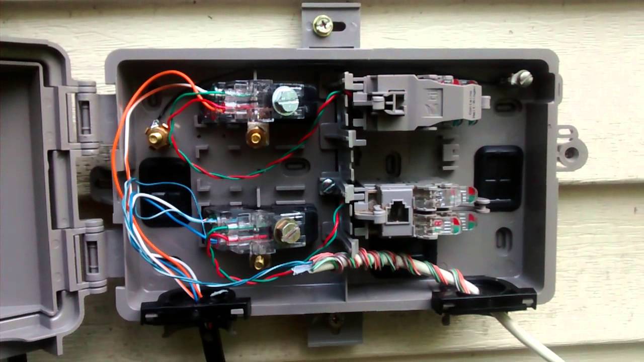
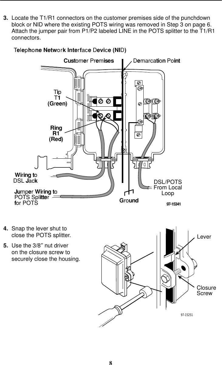
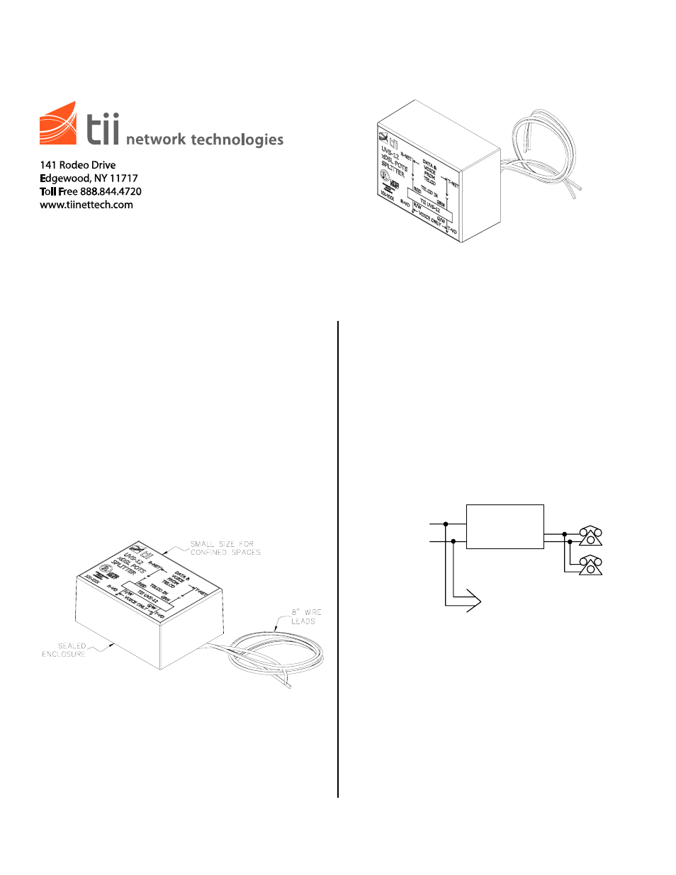
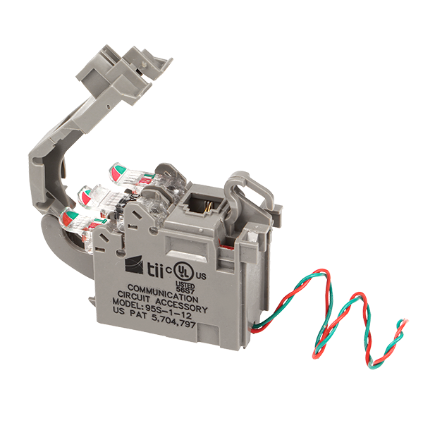
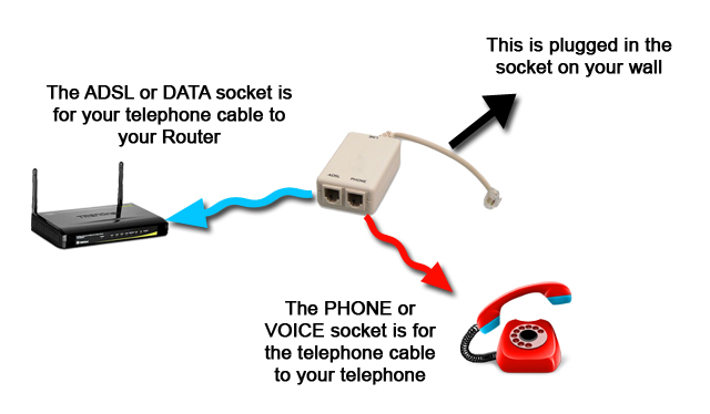
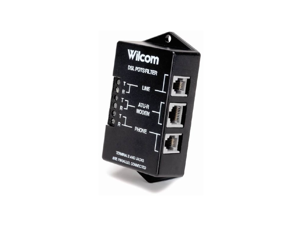
the line comes in from outside and goes to "Line" on the POTS splitter. the one jack that can carry DSL has 4 wires: red\green to "DSL modem" on POTS splitter; black\yellow to the "peg board ... disengaged (both DSL and POTS service) from the central office. Features Figure 1 Installation 1. Hold the Splitter Module with the cover pivot side on right. 2. Lower the pivot side edge inside the designated installation cavity. 3. Engage the right end ledge under the catch. (See Figure 2). 4. Push the left side end down until the latch snaps closed. The main purpose of the DSL over POTS splitter, is to separate the transmission of POTS signals and DSL signals, which enables the simultaneous transmission of both voice and data on the same twisted pair i.e. the POTS + DSL line. The splitter also provides isolation to the POTS signal from interference from DSL signals. Its also provides isolation for the DSL transmission to the POTS from transients generated during POTS signalling (i.e. dialling, ringing, ring trip, off-hook, on-hook etc.).
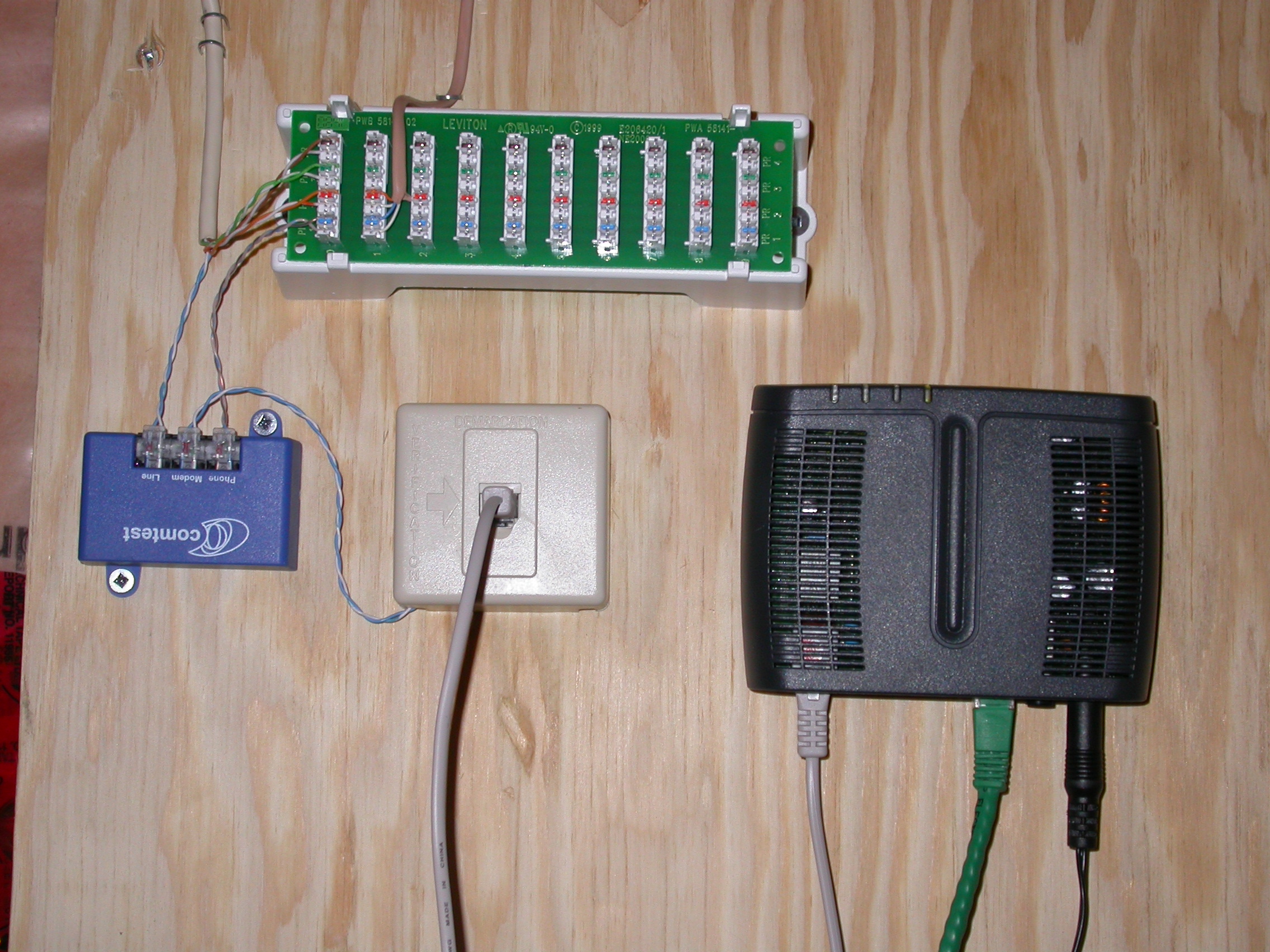
Dsl pots splitter wiring diagram. This is useful for developers who are concerned with the interaction of the POTS and DSL circuits. The user may evaluate parameters of the POTS line (On/Off hook, ringing, and analog modem signals) and measure the effects on the DSL line (data throughput, ADSL connection status). The diagram above was tested in the labs at Broadframe. The Wilcom PS-15 ADSL2+ Wall-mount POTS Splitter is a passive lowpass filter designed to provide POTS service in concert with ADSL technology. The device blocks high frequency (20kHz- >2.2MHz) energy from interfering with POTS equipment. The PS-15 employs a low-pass filter for standard voicegrade lines. Step 2: Install DSL Splitters into the NID, as previously described in Section 2. Step 3: Insert the wires from the DSL splitter into the holes in the USP until the wires touch the back of the protector (Figure 12). Step 4: Screw the stuffer back down to make contact. Gently tug on wires to check connection. Figure 12 3.3 Subscriber Wiring Jan 14, · Best Answer: The typical wiring would be that you only need to connect the red and green lines on your jack to the tip and ring of the DSL line. Inside the connector on the NID there are usually four screw terminals. The left two are connected to each other, as are the right two. Connect the red line to one Status: Resolved.
Run Cat5 For Dsl. Siecor external splitter homerun how to install a dsl line 12 2 inside telephone wiring and adsl by jules bartow technology in the microfilter nid diagram phone about infinity internet support cable modems issues last 50 feet works lmi net for doityourself doing your own run cat5 1 connection introduction pots pans nuts bolts of residential telecommunications correctly micro ... Dsl Pots Splitter Wiring Diagram Tii Network Technologies Dsl. Dsl Pots Splitter Wiring Diagram - wiring diagram is a simplified enjoyable pictorial representation of an electrical circuit. It shows the components of the circuit as simplified shapes, and the faculty and signal connections amid the devices. 4 Full Rate Adsl Arrangement With Pots Splitters The Splitter Scientific Diagram. Tii Uvs 12 User Manual 1 Page. Uvs 12 Dsl Pots Splitter Module For Vdsl2 Adsl2 Iptv Services Tii Technologies. Using Pots Splittericrofilters In A Dsl Environment Cisco. Lpf 200 Series Adsl Pots Splitters. 12 2 Inside Telephone Wiring And Adsl Dsl Advances. About Press Copyright Contact us Creators Advertise Developers Terms Privacy Policy & Safety How YouTube works Test new features Press Copyright Contact us Creators ...
Adsl Splitter Wiring Diagram. Adsl filters explained each filter part in a splitter correctly install micro lite modem installation with sharing adapter 1 configuring the rostelecom electronics repair how to wire dsl gohts wiki tutorial about installing. Each Filter Part In A Splitter Installation Has Specific Function Scientific Diagram. Dsl Pots Splitter Wiring Diagram Best Of Dsl Pots Splitter Wiring - Dsl Phone Jack Wiring Diagram. You are able to usually rely on Wiring Diagram as an crucial reference that will enable you to conserve time and cash. Using the aid of the guide, you'll be able to very easily do your own personal wiring projects. Dsl Phone Jack Wiring Diagram - dsl phone jack wiring diagram, dsl phone jack wiring diagram centurylink, dsl wall jack wiring diagram, Every electric arrangement is made up of various diverse components. Each component ought to be placed and linked to different parts in specific way. If not, the structure won't work as it ought to be. Outdoor NIDs are usually located on the outside wall.Centurylink Nid Wiring Diagram Dsl Efcaviation Of White Wire Telephone Jack Wiring Diagram - Dec 20, · from top to bottom. blue blue green green Should work. Old system was 3 wire, usually, red, white and blue, which should have been in terminals 2,5 and 3 respectively..
Comtest CPE-01V DSL Splitter on a POTS line - YouTube
Centurylink Dsl Rj11 Wiring Diagram | Wiring Diagram - Centurylink Dsl Wiring Diagram. Wiring Diagram arrives with several easy to follow Wiring Diagram Directions. It really is intended to aid all of the common consumer in developing a correct method. These instructions will likely be easy to grasp and apply.
DSL filter - Wikipedia
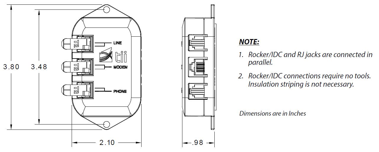
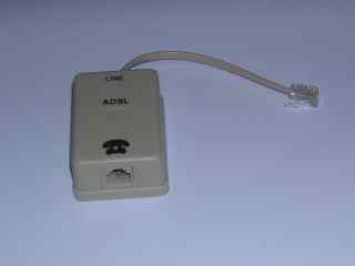
Two types of connection options are supported by the PS-36 splitter: a screw-type terminal block and standard RJ jacks. This allows the installer to simply connect the existing premise wiring to the PHONE connector or RJ jack on the splitter, and have POTS service up and running within minutes without expensive and time-consuming rewiring.
Comtest Networks NID-01V POTS Splitter Datajack User Manual ...
Utilizing New Dedicated Cat 5 Wiring - The homerun is connected to a completely new wire that is installed and dedicated just for DSL. Schematics and pictures by Andy Houtz More information about ...
Bourns® OSP Products
VDSL2 POTS Splitters and Microfilters CPE Splitter A CPE splitter has 3 connections: Line, DSL and POTS. It provides low pass filtering between the Line Port and POTS port and a HPF (high pass filter) or all pass filter between Line and DSL ports. A typical Loop configuration of CPE splitter installation is shown in Figure 3. In this situa-
New DSL Pots splitter 10mbps - YouTube
This POTS splitter was easy to install and it seems to be doing a good job. My Verizon DSL signal is horrible quality and all the tech people do is blame your house wiring. I got this splitter so I could pull out all of the tiny filters and to hook directly to my ancient 98a demarc point. SNR went from 6dB to 13dB. Not great but much better.
Need help wiring NID for new phone jack install ahead of ...
If comparing to other "splitters", make sure you are comparing equivalent devices. A true "whole-house" splitter is a filter designed and packaged to support installation in such a manner that all of the voice phone jacks and wiring are isolated from DSL jacks and wiring by one single device.
How to Belle Your Phone Line for DSL – Do Something Every Day
Wiring A Pots Line what is a firefighter s telephone system, 2 pickup guitar wiring diagrams guitarelectronics com, new dsl pots splitter 10mbps, solved u verse internet only and pots line at amp t community, doing your own telephone wiring, www hellodirect com the basics of telephone wiring, 10 0 homerun diagrams and procedures at amp t ...
o SUTTLE 1 o - Outdoor POTS Splitter
Dsl Pots Splitter Wiring Diagram. Several vendors have developed stand-alone ADSL POTS low pass filters for both customer ringing, and analog modem signals) and measure the effects on the DSL line (data The diagram above was tested in the labs at Broadframe.

Full Bonded NID Splitter with Test Jack and EMI Suppression ...
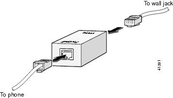
Wire the DSL wall jack (RJ11) at your computer location, which should already be connected to the DATA side of the splitter. The specifics differ for each situation, but basically you will have a wire pair that you will connect to the DSL jack. Make sure you read the directions, as the DSL-RJ11 wiring may be different for phones and DSL jacks.
Nortel Networks Backbone Link Node Router 5030 Users Manual
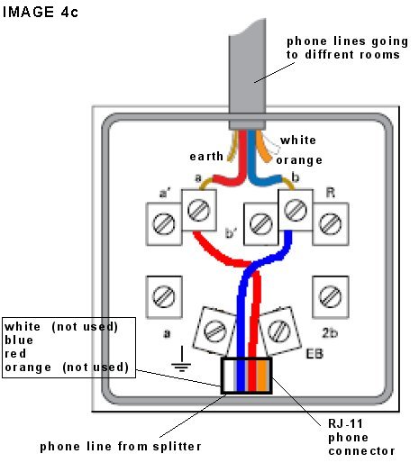
Installing the DSL Splitter Near the NID. In the diagrams on this page, pair 1 (wht/blu) = "voice" connections for line one. pair 2 (wht/org) = "voice" connections for line two (if present) pair 3 (wht/grn) = DSL data connections. pair 4 (wht/brn) = line connection from the NID to the splitter. Where possible, I would recommend actually using the pairs shown for the purposes indicated.
About DSL | Infinity Internet Support
The main purpose of the DSL over POTS splitter, is to separate the transmission of POTS signals and DSL signals, which enables the simultaneous transmission of both voice and data on the same twisted pair i.e. the POTS + DSL line. The splitter also provides isolation to the POTS signal from interference from DSL signals. Its also provides isolation for the DSL transmission to the POTS from transients generated during POTS signalling (i.e. dialling, ringing, ring trip, off-hook, on-hook etc.).
80-410V Series Indoor DSL POTS Splitter Module for VDSL2 ...
disengaged (both DSL and POTS service) from the central office. Features Figure 1 Installation 1. Hold the Splitter Module with the cover pivot side on right. 2. Lower the pivot side edge inside the designated installation cavity. 3. Engage the right end ledge under the catch. (See Figure 2). 4. Push the left side end down until the latch snaps closed.
Connecting DSL WAN Interface Cards - Cisco
the line comes in from outside and goes to "Line" on the POTS splitter. the one jack that can carry DSL has 4 wires: red\green to "DSL modem" on POTS splitter; black\yellow to the "peg board ...

DSL Network Guide Chapter 7: The NID

Splitter wiring diagram. ADSL splitters. Device. Connection ...

Type of contractor needed to connect my DSL demarcation point ...

How Splitter works. How to connect ADSL Splitter. Scheme ...
Tii UVS-12 User Manual | 1 page
About DSL | Infinity Internet Support

Presented by: Eng. Karam Al-sofy - ppt video online download
3610V3 DSL POTS Splitter

Wiring for phone and DSL - DoItYourself.com Community Forums
Mobilefish.com - A tutorial about installing ADSL in the ...

A Basic Guide to POTS/DSL Filters
361xA2 Series ADSL2+ / VDSL2 POTS Splitters
95S-1-12 DSL POTS Splitter Module for VDSL2/ADSL2+, IPTV ...
CO POTS Splitter Installation Guide

Asymmetrical Digital Subscriber Line ADSL Asymmetrical ...

Figure 4 from Introduction of a Pseudo-6 th Order ISDN ...

DIY Phone Jack Installation - Dad Goes Round

80-200 Indoor DSL Filter With Data Port - Tii Technologies
ADSL filters explained

DSL by Jules Bartow Technology In The Vein Is it Creepy or ...
About DSL | Infinity Internet Support

Everything you need to know about POTS (Plain Ordinary ...
Tii : User Manual
Siecor External Splitter Homerun Diagram AT&T Southeast Forum ...
A Basic Guide to POTS/DSL Filters
Wilcom PS-15 ADSL2+ CPE POTS Splitter with RJ-45 DSL Modem ...
ADSL filters explained
0 Response to "40 dsl pots splitter wiring diagram"
Post a Comment