38 ph diagram for refrigeration cycle
A vapour compression cyce with superheated vapour at the inlet of compressor is shown on T-s and P-h diagrams. Refer Fig. 1. In this cycce, the heat is absorbed or extracted in two stages, firstly, from point 4 to 1′ (latent heat) and secondly, from point 1′ to point 1 (sensible heat). The remaining cycle is the same. It is explained below. 1-5. This Cogitation is to base on idea simple cycle with no losses. Figure 1-5 Refrigeration Cycle on the P-H Diagram Take the structure image of this refrigeration cycle from Figure 1-5, it becomes the P-H diagram for engineering calculation as shown in Figure 1-6. The points which are required for engineering calculation are from H 1 to H
CONTROL BOXCOVER, and a header disposed adjacent to the valve plate. Diagram Awesome Refrigeration Ph Diagram Refrigeration Cycle. Browse the list of most popular and best selling audiobooks on Apple Books. Parker, be sure to disconnect all power to the unit. Part numbers of these organizations are used for cross reference and interchange ...
Ph diagram for refrigeration cycle
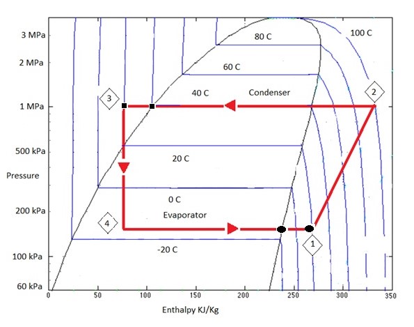
Represent the refrigeration cycle on a P-h diagram c. Determine the quality of the refrigerant at the evaporator inlet d. Determine the refrigeration load e. Determine the COP and EER of the refrigerator f. Compute the theoretical maximum refrigeration load for the same power input to the compressor Water 18°C 26°C 1.2 MPa 65°C 42°C ... On the HVAC & Refrigeration PE Exam you must have a deep understanding of the pressure-enthalpy diagram. This guide will take you through the vapor-compression cycle to better understand the P-H diagram. Changes in enthalpy correspond with the phases of the refrigeration cycle. Enthalpy significantly increases in the evaporator. This occurs because the refrigerant absorbs heat in the evaporator. On a pressure-enthalpy diagram of the ideal refrigeration cycle, you'll notice that the bottom edge of the figure will have a horizontal line.
Ph diagram for refrigeration cycle. Air-Conditioning and Refrigeration. Mechanical Engineering Handbook. Pawan Gupta. Download PDF. Download Full PDF Package. This paper. A short summary of this paper. 22 Full PDFs related to this paper. READ PAPER. Air-Conditioning and Refrigeration. Mechanical Engineering Handbook. Download. Read: Full notes on Ericson Cycle with PV and TS diagram #4 Joules cycle. Joules Cycle is also known as the Brayton cycle. It is a thermodynamic cycle named after George Brayton. It describes the workings of a constant-pressure heat engine. Consists of two constant pressure and two adiabatic processes. The refrigeration cycle is composed of repetition of the following process. "Compression ? Condensation ? Expansion ? Evaporation" The refrigerating machine conducts above cycle with compressor, condenser, expansion valve and evaporator. Theoretic refrigeration cycle neglecting pressure loss, etc. drawn on P-H diagram is shown as above. The log p-h diagram shows the thermodynamic state vari- ables in the respective phase. • pressure p. • specific enthalpy h. • temperature T. • specific volume v.2 pages
T4/2. Output. Power to run Coolant Fans V7 and V35 at 1st speed when the A/C is. After a 3am wake up call to boil the kettle and a 4am set off on the trial, we go to the summit of Pen Y Fan just in time for the sunrise that day. And what a sunrise it was! 2004 Jetta Coolant Control Module Wiring Diagram 1999 VW ... In addition, a cycle temperature-entropy (T-s) diagram at the isobutane ratio of 0.8 in the mixture is displayed in Fig. 9. Thick solid line is T-s diagram of refrigerant mixture, and dashed line and dashed dot line are secondary fluid temperature variation in the condenser and evaporator, respectively. The vapor compression refrigeration cycle consists of four processes: (1-2) compressing refrigerant in compressor isentropically, (2-3) condensation at constant ... The regenerative Rankine cycle is so named because after emerging from the condenser (possibly as a subcooled liquid) the working fluid is heated by steam tapped from the hot portion of the cycle. On the diagram shown, the fluid at 2 is mixed with the fluid at 4 (both at the same pressure) to end up with the saturated liquid at 7.
Refrigeration handbook 1. Basic heat transfer 2. Compression cycle 2.1 The pressure-enthalpy diagram; 2.2 Basic components; 2.3 The basic cycle in a log Ph diagram; 2.4 The complex cycle in a log Ph diagram; 2.5 Other components; 3. Compressors 4. Expansion valves 5. Refrigerants 6. Evaporators 7. Condensers 8. P h head pressure absolute psia p s suction pressure absolute psia. Done on the refrigerant flow rate H3-H2 compressor. What steps or formula would I need to use to calculate mass flow of refrigerant 134a for a refrigerator. But if you want the mass flow rate it is around 128 - 135 lbmhr for an 18 cu ft. Pressure bar Enthalpy kJkg. The optimum intermediate pressure for the two-stage refrigeration cycles is determined as the geometric mean between evaporation pressure (pl) and condensing pressure (ph, Fig. 11-79): based on equal pressure ratios for low- and high-stage compressors. Jul 23, 2014 - **Researching Refrigeration Compressors and Air Conditioning Compressors? Start with this definitive resource of key specifications and ...
Solved: An Ideal Vapor-compression Refrigeration Cycle Use ...
How does basic refrigeration cycle work? The basic refrigeration cycle for beginners If you are interested in learning how a refrigeration system works, it is helpful to understand from the Ph (Pressure Enthalpy) chart perspective. It makes our life much easier. This is how the refrigeration cycle diagram looks:

Natracare's regular ultra period pads
Schematic diagram of joule-Thomson refrigeration (single MR) cycle. The specific working principle of single MR refrigerators is as follows. The refrigerant vapor sucked by the compressor flows into the aftercooler in a state of high temperature and high pressure through the compression process (1-2a).

Efficiency - Measuring Refrigeration
Air Conditioning Refrigeration Cycle - 9 images - refrigeration cycle stock vector image 42808207, the refrigeration system and components part 3 youtube,

Natracare organic cotton curved panty liners
Understanding P-H Diagram. Posted in Beginner CRS. Understanding P-H Diagram Posted by By Aung Myat Thu November 28, 2021. ... Understanding of Basic Refrigeration Cycle. Next Post. Understanding of Refrigerants. Quote. Help your country with your knowledge! Share your knowledge with your generation! Online Courses. Home; About Us;
Ph Diagram For Refrigeration Cycle - Diagram For You
Ideal refrigeration cycle or reversed Carnot cycle. If we analyse it from a more intuitive point of view, we can see that the smaller the temperature difference, the pressure ratio is lower, and the compressor needs to perform less specific work for that pressure difference. ... This can be clearly seen in the P-h diagram. With floating ...

2018 Prudential Classic participants race down Putney High Street towards the end of the race
Exercise 2-4: Implement the sub-cooling cycle in Pro II and report the new COP. Phase diagram is a graphical representation of the physical states of a substance under different conditions of temperature and pressure.Figure 2-8: TS and P-H diagram for liquid sub-cooling in a refrigeration cycle.

Heat pump - Wikipedia
Simple Refrigeration Cycle - 9 images - applications of refrigeration and air conditioning, typical refrigeration cycle stock vector illustration of, ... Ph Diagram Refrigeration Cycle. Ideal Refrigeration Cycle. HVAC Basic Refrigeration Cycle. Refrigeration System Cycle.
34 Ph Diagram For Refrigeration Cycle - Free Wiring ...
The Carnot Cycle describes the operation of refrigerators, the Otto Cycle describes the operation of internal combustion engines, and the Brayton Cycle describes the operation of gas turbine engines. P-V and T-s diagrams are often used to visualize the processes in a thermodynamic cycle and help us better understand the thermodynamics of engines.

Vapor-Compression Refrigeration Cycle (Interactive ...
Next, the working fluid can expand to the two-phase state. The low-temperature and vaporized refrigerant is passed into the evaporator and the refrigeration effect is produced. Figure 1 shows the refrigeration cycle state point (R134a as an example) in the P-h diagram. The mathematical expressions for the simulation are presented below.

Refrigeration: Refrigeration Ph Chart
Refrigerant Ph Diagram. For a Carnot cycle (where A Q = TA s), the COP for the refrigeration application becomes (note than T is absolute temperature [K]): Thigh_ Tio and for heat pump application: The COP in real refrigeration cycles is always less than for the ideal (Carnot) cycle and there is constant effort to achieve this ideal value.

Natracare biodegradable and organic ultra pads
The refrigeration plants on merchant vessels play a vital part in carrying refrigerated cargo and provisions for the crew on board. In reefer ships, the temperature of the perishable or temperature sensitive cargo such as food, chemical, or liquefied gas, is controlled by the refrigeration plant of the ship.

Efficiency - Measuring Refrigeration
superheat. The Ideal Cycle. If the operating temperatures and pressures are known, the refrigeration system can be plotted on the P-H diagram. Let's.
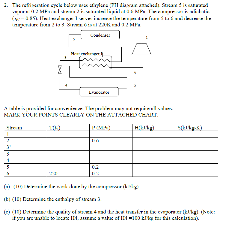
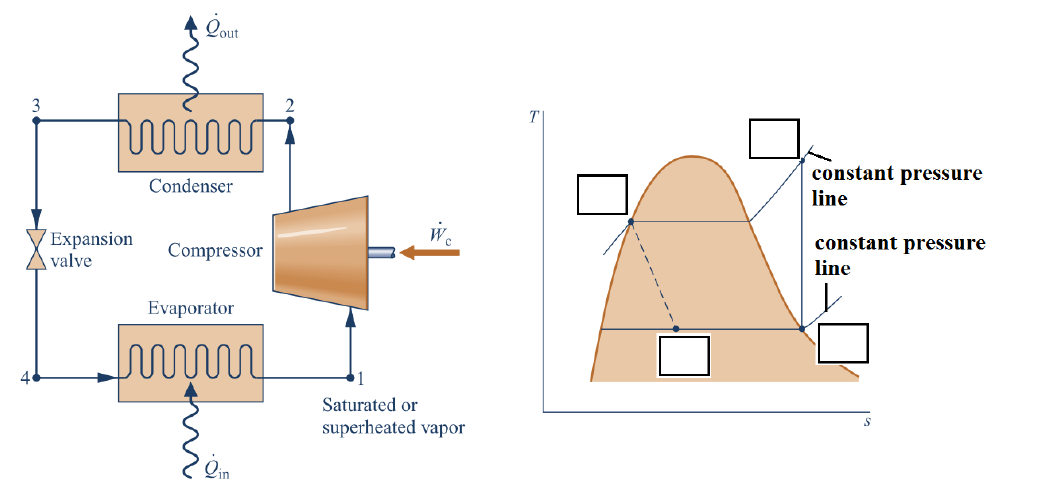
Solved: The Refrigeration Cycle Below Uses Ethylene (PH Di ...
Mar 20, 2018 — When you can draw a refrigeration cycle on a p-h diagram, you can easily obtain the refrigerant characteristics through the diagram.
Refrigeration: Ph Chart Refrigeration Cycle
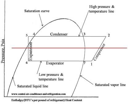
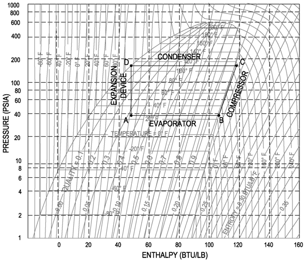
Please note this is an ideal refrigeration diagram. There is no superheat exiting the evaporator or subcooling exiting the condenser. For a more detailed explanation of the P-H diagram, please refer to Sporlan Form 5-200 in our website's literature section under HVACR Educational Material. Figure 1. Condenser:
What is meant by refrigeration effect? - Quora
An example is an industry which needs low-temperature refrigeration for a process and which must also provide air conditioning for some offices. Figure 16-8a shows one method of arranging this system, and Fig. 16-86 shows the corresponding pressure-enthalpy diagram. In Fig. I6-80

Closeup of skeleton pelvic model
The process of energy conversion electrical to mechanical, gas to vapour, mechanical to heat. 2.3. Meaning of internal energy. 2.4. Enthalpy of a fluid substance, its pressure, volume and temperature of internal energy. 2.5. The ph diagram of refrigerant. 2.6. State of matter - solid, liquid, gas or vapour.

Refrigeration: Refrigeration Ph Chart
All refrigerant properties were calculated by EES (Engineering Equation Solver), version 10.103, based on the standard reference state of the International Institute of Refrigeration. 30 Figure 4 shows the superimposed P-h diagrams of R134a/R744 and R438A/R744 pairs, respectively. Evaporation and condensation isotherms and thermodynamic states ...

Visited edinburgh in Scotland over the christmas period. sadly didnt get out much to take pictures. However, here’s a quick grab shot of a cyclist. Not one of my finest works, but I just love the way the sun lights the scene and the dudes hair.
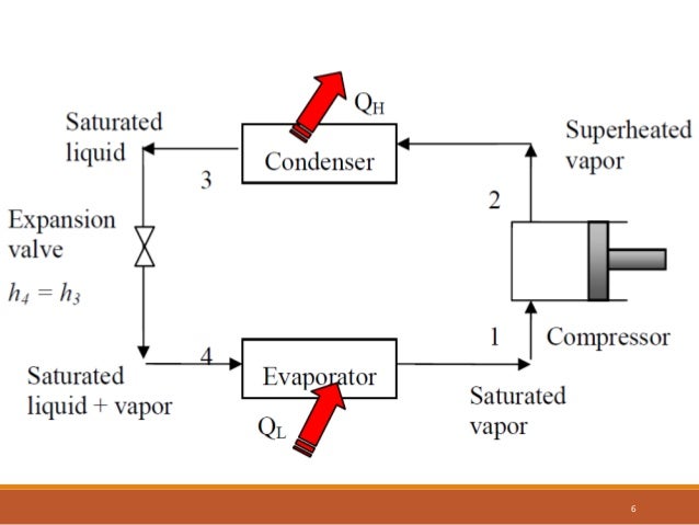
The expansion process is assumed to be adiabatic (a) Sketch both a schematic diagram of the refrigeration plant, and a state diagram of the thermodynamic cycle on a P-h diagram, including labelling each process and numbering the state points between processes, starting with number one at the beginning of the compression process Indicate each ...

Tampons on Unsplash
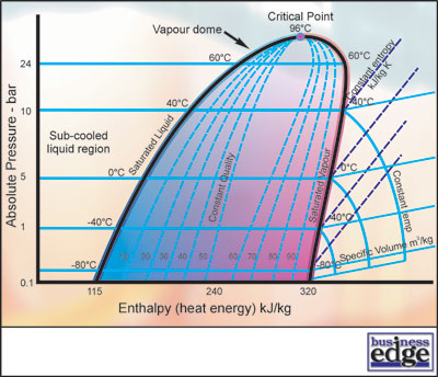
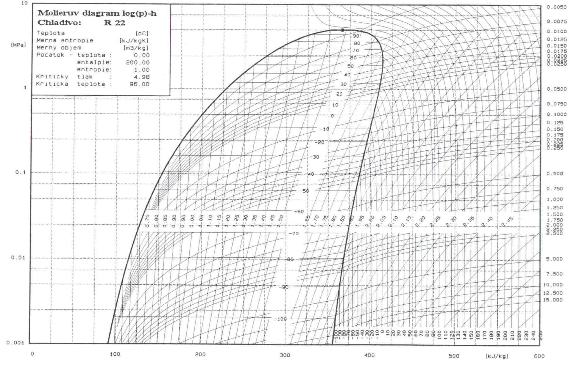
R22 P/H Diagram * Diagram created using REFPROP – NIST Reference Fluid Properties As can be seen, the critical point of R-22 is more than 200°F, placing it well above the operating conditions of typical refrigeration systems. This can be contrasted with the CO 2 PH diagram, with a critical point of 88°F.
Ph Diagram For Refrigeration Cycle - General Wiring Diagram
Principles of Refrigeration MAE 554 Professor H. Ezzat Khalifa Syracuse University P-h Chart for R134a (SI Units) 2 Psychrometric Chart (ASHRAE) Psychrometric Processes Cool Heat Humidify ... P-h Diagram for Real Vapor Compression Cycle Effect of the Gas Specific Heat Ratio, ...

Ph Diagram For Refrigeration Cycle - General Wiring Diagram
2 972 How A Compression Refrigeration System Works. Schematic diagram of the refrigeration simple cycle explained in basic 2003 06 air system basics controls understanding pressure control typical vapor compression domestic equipment kolpak drop systems main components true freezer wiring an overview circuit 1 modern and a factory conditioning self contained wire low r404a two stage cur relay ...

Refrigeration: Refrigeration Ph Cycle
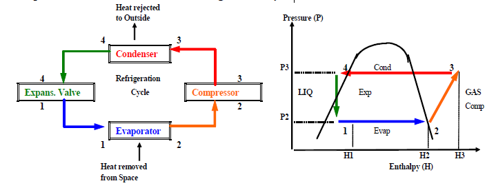
There it is compressed, thus the pressure goes up. This process is represented in p-h diagram as 1-2. This high pressure vapour enters the condenser. There, it looses its latent heat and becomes liquid. (Process 2-3) The liquid refrigerant is stored in a receiver and supplied to the expansion valve, and the cycle continues.

Pressure enthalpy diagram of a propane refrigeration cycle ...
Figure 2-4: Wet refrigeration Cycle - The expander has been substituted by a throttling valve. If an expander had been used the line from d to a would be a vertical line. This is also done for mechanical reasons. The refrigeration cycles can also be represented in a P-H diagram. Figure 2-5: P-H diagram representation of a dry refrigeration cycle
Gases & Liquids (Fluids) and Solids: | Energy-Models.com
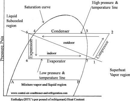
Understanding the basic refrigeration cycle diagram also helps us to find subcooled, superheat and to troubleshoot refrigeration processes much easier. As we can see in the Ph diagram below. Saturation curve this curve represents what state (vapor or liquid) and region (sub-cooled, latent heat, and superheat) the refrigerant is in.
Refrigeration: Refrigeration Ph Chart
Also draw p-h and T-s diagram for the same. 0 0 SMDARJI Tuesday, January 26, 2021 Vapour Compression Refrigeration Syestem. A Schematic diagram of simple vapour compression refrigeration(VCR) cycle is shown in fig. Vapour compression refrigeration cycle:
Ph Diagram For Refrigeration Cycle - Drivenheisenberg
Figure 2 a shows the vapor compression cycle incorporating the IHX, while Figure 2 b presents a Ph diagram showing the thermodynamic states of the refrigerant in the refrigeration cycle. The dotted lines indicate the modification of the cycle when introducing the IHX, which produces an increase in the cooling capacity.

Schematic diagram of an ejector refrigeration cycle and ...
Changes in enthalpy correspond with the phases of the refrigeration cycle. Enthalpy significantly increases in the evaporator. This occurs because the refrigerant absorbs heat in the evaporator. On a pressure-enthalpy diagram of the ideal refrigeration cycle, you'll notice that the bottom edge of the figure will have a horizontal line.

Vapour Compression Refrigeration System - YouTube
On the HVAC & Refrigeration PE Exam you must have a deep understanding of the pressure-enthalpy diagram. This guide will take you through the vapor-compression cycle to better understand the P-H diagram.
Basic Refrigeration Cycle
Represent the refrigeration cycle on a P-h diagram c. Determine the quality of the refrigerant at the evaporator inlet d. Determine the refrigeration load e. Determine the COP and EER of the refrigerator f. Compute the theoretical maximum refrigeration load for the same power input to the compressor Water 18°C 26°C 1.2 MPa 65°C 42°C ...

How Air Conditioning Works - The Basics - HVAC Tutors
Fun Practice and Test: Vapour Refrigeration Cycle
Ph Diagram For Refrigeration Cycle - Drivenheisenberg

P-h diagram of ½ cycle refrigeration on LPG fueled vehicle ...
P-H Diagram Thermodynamics | HVAC and Refrigeration PE ...
Basic Refrigeration Cycle
Refrigeration: Refrigeration Ph Chart
Refrigeration: Refrigeration Ph Chart
![[DIAGRAM] Ph Diagram R134a Calculator FULL Version HD ...](https://i.ytimg.com/vi/b1F5EnMr8us/maxresdefault.jpg)
[DIAGRAM] Ph Diagram R134a Calculator FULL Version HD ...
0 Response to "38 ph diagram for refrigeration cycle"
Post a Comment