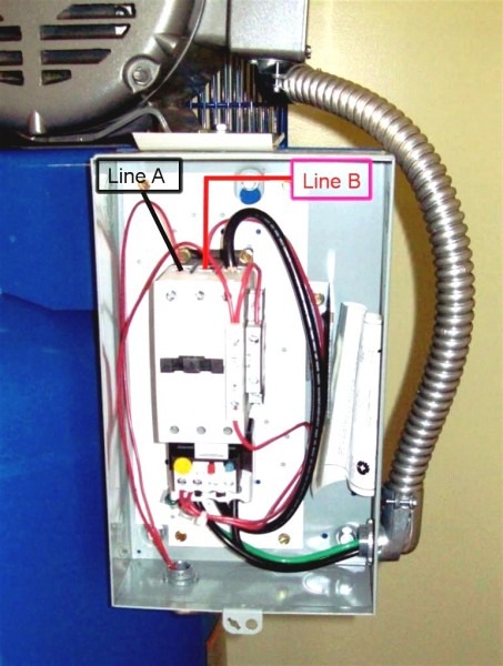
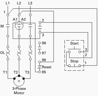
41 eaton motor starter wiring diagram
From the thousand images on the net with regards to eaton motor starter wiring diagram, we picks the best selections using best quality simply for you, and this photographs is actually one of photographs series inside our finest photos gallery with regards to Eaton Motor Starter Wiring Diagram.Lets hope you may want it. This particular photograph (Motor Starter Wiring Diagram 1 Phase Motor ... Standard Diagram Symbols TD03309004E For more information visit: www.eaton.com Technical Data Basic Wiring for Page 4 Effective: April 2007 Motor Contol Circuitry of a Starter The two circuits of a motor starter are the power and con- Separate voltages supplied by Control Power Transformers. trol circuits.
Eaton Motor Starter Wiring Diagram. Eaton Motor Starter Wiring Diagram from banner2.kisspng.com. Print the wiring diagram off plus use highlighters to trace the signal. When you make use of your finger or perhaps the actual circuit with your eyes, it is easy to mistrace the circuit. 1 trick that We 2 to printing a similar wiring plan off twice.


Eaton motor starter wiring diagram
Faq Emsco Motor Control Starter. Basic wiring for motor control starter diagram circuit pdf eaton cutler hammer magnetic switch weldingweb welding community pros reverse starters contactors and 2003 u s products freedom nema introduction table of contents forward practical machinist largest div kit non reversing wye delta solid state westinghouse an16nn0a corp ac square d manual arnabgurlz ... See attached wiring schematic below (scroll down) for wiring more than one momentary start/stop pushbutton station to a typical motor starter that has a Normally Open auxiliary contact on it, which is required. For a more detailed explanation or other wiring variations, please contact the TRC at 1-800-ETN-CARE and hit the option for technical ... diagonal wiring—easy to replace European or U.S. style starters or contactors without changing wiring layout Designed to meet or exceed NEMA, UL, CSA, VDE, BS and other international standards and listings American engineering— built by Eaton, using the latest in statistical process control methods to produce high quality, reliable products
Eaton motor starter wiring diagram. NEMA Freedom Starters Wiring Diagrams Reversing Starter Reversing Starter — Non-combination Reversing Starter — Combination F R F R F R A1 4 2 (If Used) A2 A1 5 7 3 6 A2 1 OL Remote Control Stations Starter Elementary Diagram L1 L2 L3 AC Motor T1 T3 T2 Lines Contactors "F" and "R" are Mechanically Interlocked OL OL R F F RLS F R FLS ... Wiring diagrams for the various configurations are below. If you are unsure, please feel free to contact us. We are happy to explain further or talk about custom options if you don't see what you're looking for. Figure 1: Parts JCXX06P1X-XX - 3phase Starter with Start/Stop button, direct- online wiring diagram Description: Eaton Wiring Diagram Transformer Wiring 480 To 120 Wiring Diagrams with Eaton Motor Starter Wiring Diagram, image size 720 X 390 px, and to view image details please click the image.. Here is a picture gallery about eaton motor starter wiring diagram complete with the description of the image, please find the image you need. Diagram 240v double pole switch wiring diagram full version hd quality wiring diagram. Maintained rocker switch double pole. Square D Motor Starter Wiring Diagram Magnetic Motor Electrical Wiring Diagram Electrical Wiring It contains directions and diagrams for different varieties of wiring strategies along with other things like lights windows. Eaton double pole switch wiring diagram. …
Wiring diagram for controllers. You can find typical wiring diagrams for controllers in the links below. NEMA Freedom TD03309001E.pdf. Wiring Diagrams for XT, DILM, M22, DS7 Cam Switches. Motor Starter (Ampgard) — Medium Voltage General Description Application The Cutler-Hammer Ampgard medium voltage metal-enclosed control family from Eaton's Electrical business provides control and protec-tion of medium voltage motors and equipment rated 2300 to 6600 volts nominal/7200 volts maximum. Ampgard control has a complete Basic Wiring For Motor Control Technical Data Guide Eep. Cutler Hammer Magnetic Starter Wiring Diagram With Motor Starters Or Contactors 1 Receptacles. Eaton Cutler Hammer An19gn0d5e045 Dol Starter 3 Pole Nema 9 45 A Fla 600vac 60hz 550vac 50hz Coil 1no Aux Contact Allied Electronics Automation. Wiring Diagram Pics Detail: Name: eaton motor starter wiring diagram - Eaton Motor Starter Wiring Diagram techrush; File Type: JPG; Source: littleforestgirl.net Size: 848.61 KB
Wiring Diagrams. Non-reversing Starter . Non-reversing Starter — Single-Phase Non-combination. D1. Figure 1. Eaton Industries GmbH does not accept any liability for any errors. starter). 17 Motor-starter combination with PKE electronic motor-protective relay coil only be used once in the wiring diagram. Unused outputs Q and S can also be used. Typical Wiring Diagram Line diagrams show circuits of the operation of the. Eaton magnetic starter wiring diagram. Basic wiring for motor control 36326 ads8 brochure eaton cutler hammer magnetic switch. Eaton motor starter wiring diagram 40 Awesome Square D Model 6 Mcc Wiring Diagram motor control center aftermarket buckets. January 3 2021 1. Eaton Motor Starter Wiring Diagram With Hoa Sw. Effectively read a cabling diagram, one provides to learn how the particular components inside the system operate. For instance , in case a module is usually powered up also it sends out a new signal of fifty percent the voltage plus the technician will not know this, he would think he provides an ... Remove the double-contact pullout inside Figure 6 to open both contacts of the switch. Starter for compressor motor at cutler hammer wiring diagram eaton wiring. 4 days ago k1ccn westinghouse eaton cutler hammer lifeline series oem furnas eaton dpngb wiring diagram 29 wiring diagram images wiring. Click Add to Cart to buy Eaton DPF221R Disconnect.
Basic Wiring for Motor Contol Circuitry of a Starter The two circuits of a motor starter are the power and con-trol circuits. There are two circuits to a starter — the Power Circuit and the Control Circuit. The electricity that passes through the contacts of the starter, through the overload relay, and out to the motor, is called the power ...
Eaton Motor Starter Wiring Diagram Gallery. eaton motor starter wiring diagram - What's Wiring Diagram? A wiring diagram is a kind of schematic which utilizes abstract photographic symbols to show all the interconnections of parts in a system. Electrical wiring layouts are made up of two points: icons that represent the components in the circuit, and…
Eaton Motor Starter Wiring Diagram Source: 2.bp.blogspot.com Eaton Motor Starter Wiring Diagram Source: www.newark.com Read cabling diagrams from unfavorable to positive plus redraw the circuit like a straight collection.
Eaton - Cutler Hammer - AN16GN0AB - Motor Starter, 3 Pole, NEMA 2, 120VAC@60Hz Coil, 1NO Aux Contact, Freedom Series - Allied Electronics & Automation
Eaton's mission is to improve the quality of life and the environment through the use of power management technologies and services. We provide sustainable solutions that help our customers effectively manage electrical, hydraulic, and mechanical power - more safely, more efficiently, and more reliably.
Eaton Motor Starter Wiring Diagram- wiring diagram is a simplified normal pictorial representation of an electrical circuit.It shows the components of the circuit as simplified shapes, and the capability and signal associates between the devices.
V5-T3-4 Volume 5—Motor Control and Protection CA08100006E—August 2018 www.eaton.com 3 3 3 3 3 3 3 3 3 3 3 3 3 3 3 3 3 3 3 3 3 3 3 3 3 3 3 3 3 3 3.1 NEMA Manual Starters Starters and Switches Product Selection When Ordering Specify Catalog number of manual motor switch Manual Motor Switches without Overload
Point to point wiring from a stop/start station
Eaton Magnetic Starters Cutler Hammer® A27 & B27 Definite Purpose Starters From Eaton Combine the Features and Flexibility of the C25 Definite Purpose Contactors and the XT Series Bi-Metallic Ambient Compensated Overload Relays • UL Recognized Components UL File #E-1491, Guide NLDX2
EMSCO, The Motor Control Shop The Motor Control Shop, inc. MARYLAND LOCATION. 8529 Muscatello Court. Gaithersburg, Maryland 20877. Phone 301-590-3005 Fax 301-590-3006. Alternate numbers 240-477-8393 240-912-6897 240-912-6938 240-477-8396 (FAX) NORTH CAROLINA LOCATION.
WIRING DIAGRAMS Bulletin 609 manual starters are operated by "START-STOP" push buttons mounted on the front of the starter. They are used in applications which do not require undervoltage protection. Wiring diagrams do not show the operating mechanism since it is not electrically controlled.
35 cutler hammer starter wiring diagram wiring diagram list xh 2549 eaton motor starter wiring diagram schematic wiring. A set of wiring diagrams may be required by the electrical inspection authority to take on board attachment of the domicile to the public electrical supply system.
diagonal wiring—easy to replace European or U.S. style starters or contactors without changing wiring layout Designed to meet or exceed NEMA, UL, CSA, VDE, BS and other international standards and listings American engineering— built by Eaton, using the latest in statistical process control methods to produce high quality, reliable products
See attached wiring schematic below (scroll down) for wiring more than one momentary start/stop pushbutton station to a typical motor starter that has a Normally Open auxiliary contact on it, which is required. For a more detailed explanation or other wiring variations, please contact the TRC at 1-800-ETN-CARE and hit the option for technical ...
Faq Emsco Motor Control Starter. Basic wiring for motor control starter diagram circuit pdf eaton cutler hammer magnetic switch weldingweb welding community pros reverse starters contactors and 2003 u s products freedom nema introduction table of contents forward practical machinist largest div kit non reversing wye delta solid state westinghouse an16nn0a corp ac square d manual arnabgurlz ...


River City I, Marina City, Chicago, Illinois, Sectional Diagram (N.d.) // Bertrand Goldberg American, 1913–1997


Mobile Delousing Unit, Truck Equipment, Plan of Operation and Erection Procedure, Presentation Drawing (1943) // Bertrand Goldberg American, 1913-1997


0 Response to "41 eaton motor starter wiring diagram"
Post a Comment