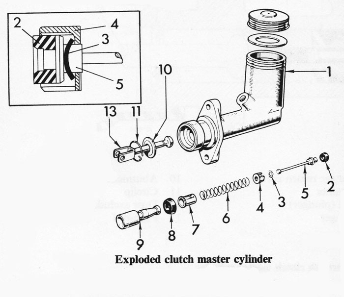
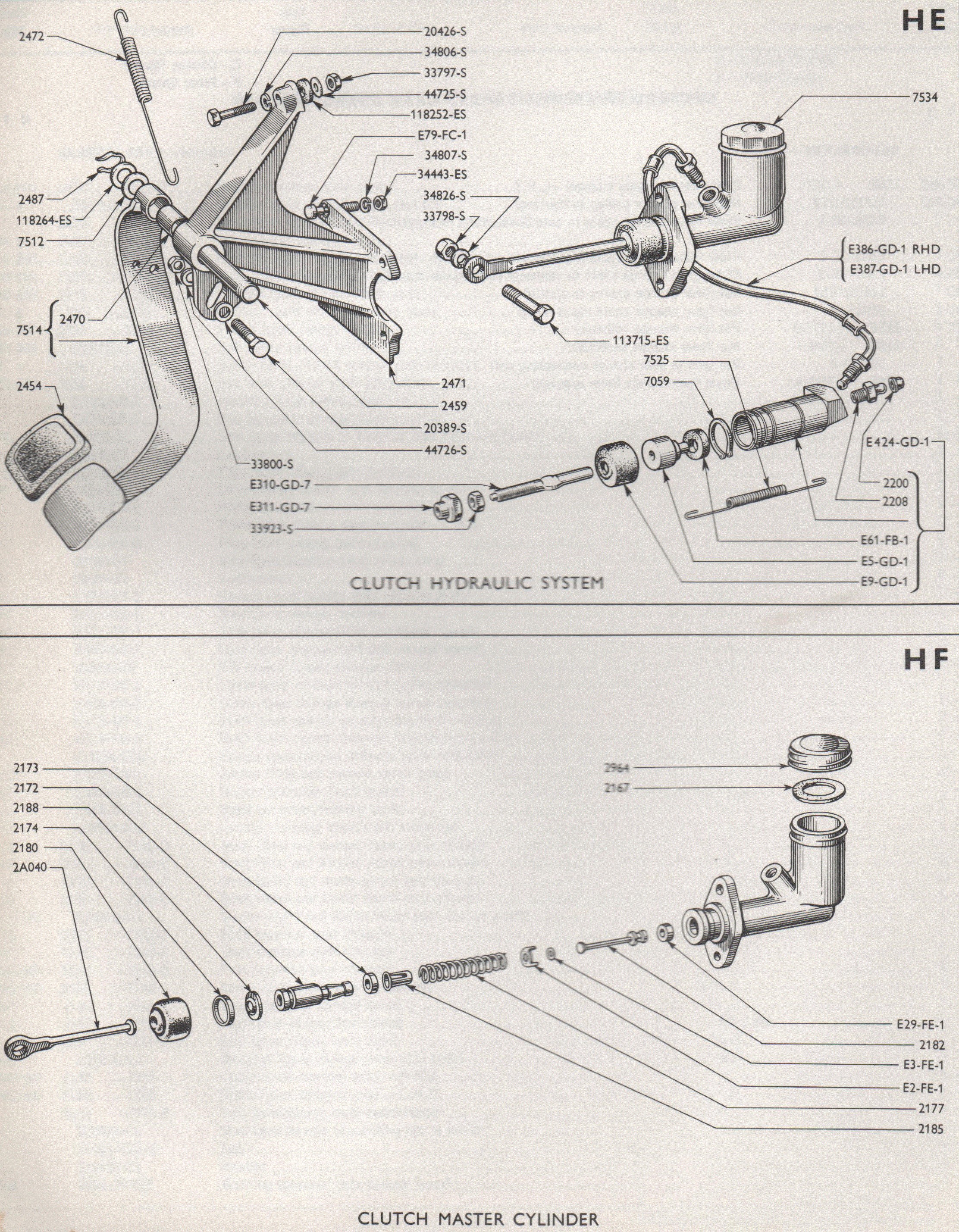
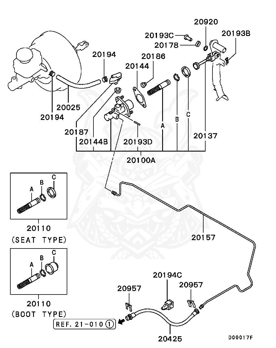
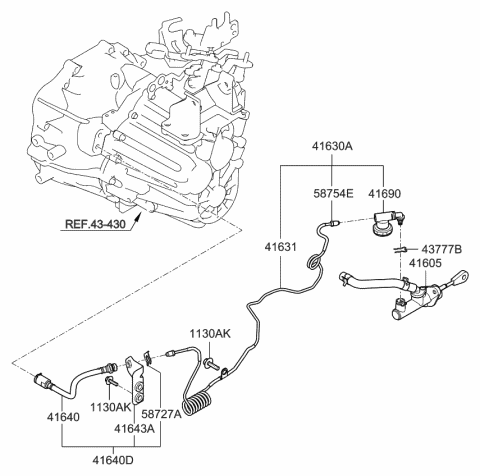
41 clutch master cylinder diagram
The adjustable master cylinder pushrod is correctly adjusted when the clutch can be released (clutch pedal depressed) to select a gear and while engaged (clutch pedal up) the pushrod is not applying pressure to the hydraulic system. LOCATE THE MASTER CYLINDER PUSHROD; REFER TO Fig. 1 & 2. 1. Loosen the lock nut on the pushrod. 2. Jun 08, 2018 · clutch master · clutch slave. We collect a lot of pictures about Clutch Master Cylinder Diagram. and finally we upload it on our website. Many good image inspirations on our internet are the best image selection for Clutch Master Cylinder Diagram. . If you’re satisfied with some pictures we provide, please visit us this page again, do not ...
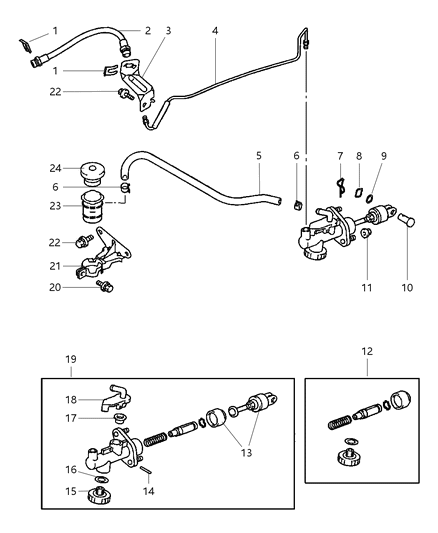
Your vehicle deserves only genuine OEM Mopar parts and accessories. To ensure reliability, purchase Mopar part # 68265776AA MASTR Cylinder-Clutch.It is sometimes referred to as Mopar Clutch Master Cylinder. Our Mopar parts and accessories are expedited directly from authorized Mopar dealers strategically located all across the U.S. and are backed by the manufacturer's 12 month, 12,000 mile ...
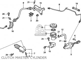
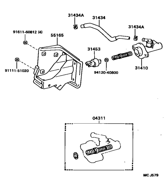
Clutch master cylinder diagram
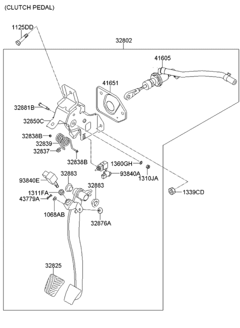
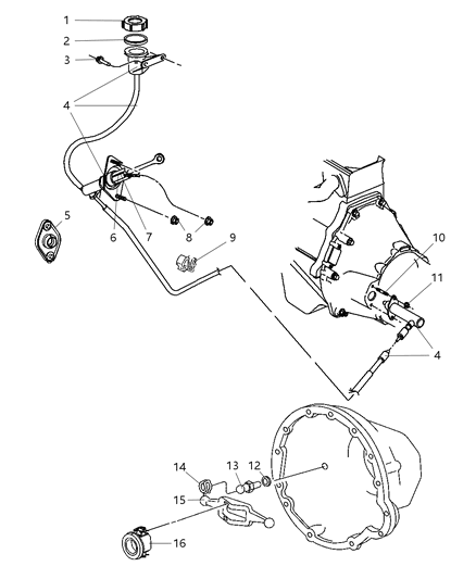
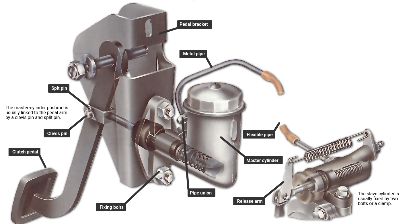
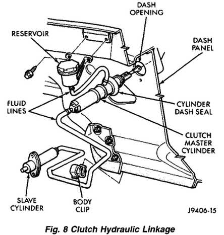
This picture shows the various connections that hold the clutch master cylinder in place. 1. the two 10mm bolts securing the master cylinder in place (green arrows), the clutch safety switch (red arrow), the pressure line to the slave cylinder (purple arrow), and the plastic pivot bolt that mechanically connects the master cylinder to the clutch pedal (yellow arrow) Oct 06, 2017 · Clutch Pedal Bracket And Master Cylinder Replacement, size: 800 x 600 px, source: home.insightbb.com. Right here are some of the top drawings we obtain from different sources, we wish these pictures will serve to you, and with any luck really pertinent to what you desire about the Ford Clutch Master Cylinder Diagram is. Master cylinders are an important component of many vehicles. They convert the applied force of the foot or fingers into hydraulic pressure. A master cylinde...
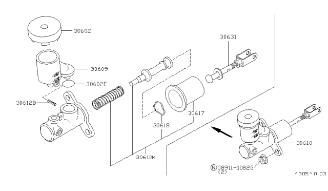
Clutch master cylinder diagram. 2) Step on pedal- Fluid from master cylinder pressure pushes the slave piston and push rod, (to the left in diagram), which moves the clutch arm, which pushes the throw-out bearing into the pressure plate to disengage the clutch. Honda CBR1000RR A CLUTCH MASTER CYLINDER Diagram. Catalog; Honda; Motorcycle; 2004; CBR1000RR A; CLUTCH MASTER CYLINDER; Check Availability. Select your address # Description Price Qty; 1: ROD, PUSH 22884-MAT-E01 Ships in 2 to 3 days. $17.64 $16.41 Add . 2: BUSH 22885-MB0-006 In Stock. $11.79 $11.51 Add . 3: PISTON SET, MASTER CYLINDER 22886 ... a hydraulic reservoir, master cylinder, hydraulic hose, slave cylinder, and clutch pedal. When the clutch pedal is depressed, fluid from the master cylinder forces the slave cylinder to move the clutch release fork. Upon release of the clutch pedal the fluid is returned to the reservoir. Master Cylinder The master cylinder is located on Title: 2022 KX™450 Clutch Master Cylinder Parts Diagram Author: Kawasaki Motors Corporation U.S.A. Subject: Vehicle Parts Diagram
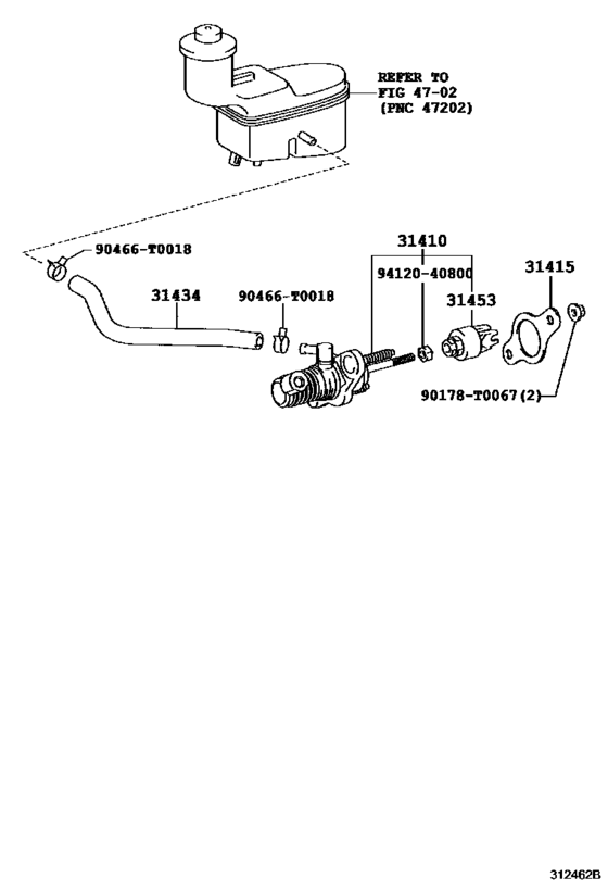
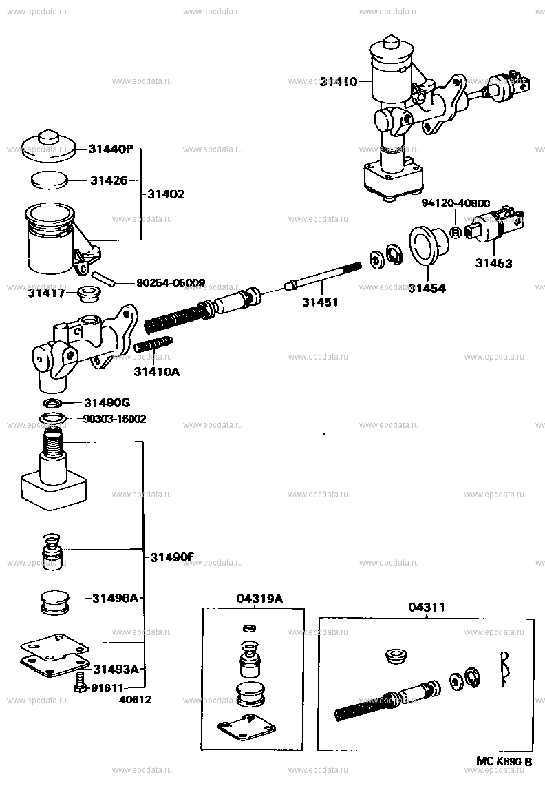
Bosch Clutch Master Cylinder Kit - K8274X. Bazaarvoice SAP Hybris Integration Version 2.8.0. Select Store. Hurry Sale Ends - 29/11/2021. In-Store. Not Available. In-Store. Not Available. In-Store. Clutch Master Cylinder ([03.1969 - 04.1977] (6903-7704)DA11#,DB10#,FA100,11#,FC100) Diagram Toyota HEAVY DUTY TRUCK . Year 1969 - 1974 Sales region General Frame DB102 ENGINE 2D DESTINATION GEN From 03.1969 To 03.1974 Gear Shift Type 5F Driver's Position LHD Transmission Model 5FO Master cylinders are an important component of many vehicles. They convert the applied force of the foot or fingers into hydraulic pressure. A master cylinde... Oct 06, 2017 · Clutch Pedal Bracket And Master Cylinder Replacement, size: 800 x 600 px, source: home.insightbb.com. Right here are some of the top drawings we obtain from different sources, we wish these pictures will serve to you, and with any luck really pertinent to what you desire about the Ford Clutch Master Cylinder Diagram is.
This picture shows the various connections that hold the clutch master cylinder in place. 1. the two 10mm bolts securing the master cylinder in place (green arrows), the clutch safety switch (red arrow), the pressure line to the slave cylinder (purple arrow), and the plastic pivot bolt that mechanically connects the master cylinder to the clutch pedal (yellow arrow)


0 Response to "41 clutch master cylinder diagram"
Post a Comment