40 fuel sending unit wiring diagram
Wiring Diagram Fuel Gauge Manual - Today Wiring Diagram - Fuel Gauge Wiring Diagram Wiring Diagram consists of many in depth illustrations that show the connection of varied things. It includes guidelines and diagrams for various types of wiring strategies as well as other things like lights, home windows, and so on. About Press Copyright Contact us Creators Advertise Developers Terms Privacy Policy & Safety How YouTube works Test new features Press Copyright Contact us Creators ...
Fuel Sending Unit Wiring Diagram. Fuel Sending Unit Wiring Diagram - wiring diagram is a simplified normal pictorial representation of an electrical circuit. It shows the components of the circuit as simplified shapes, and the capacity and signal associates between the devices. A wiring diagram usually gives suggestion not quite the relative ...
Fuel sending unit wiring diagram
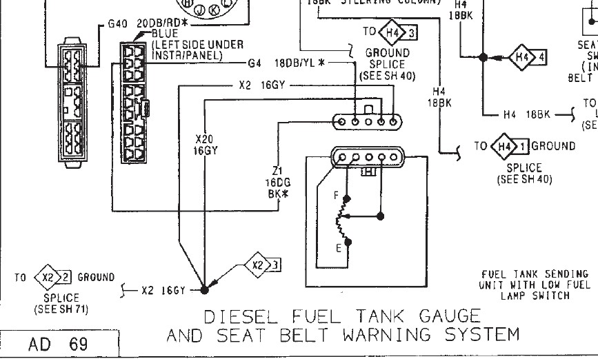
Marine Fuel Gauge Wiring Diagram . March 16, 2019 ... Fuel gauge and sending unit wiring the hull truth smiths e troubleshooting dual units to one engine instrument made easy my doesn t work if it is cell. How To Test And Replace Your Fuel Gauge Sending Unit Sail Magazine Joined Nov 9, 2020. ·. 2 Posts. #6 · Nov 9, 2020. Patrick Feeley said: Here's the 97 wiring diagram. 94-97 are the same. Note the Diesel diagram only shows two wires for each of the sending units. The gas diagram has an additional two wires shown for each sending unit for the integral pump (which the diesels don't have). Cheers! 1973-1977 Monte Carlo Fuel Tank Sending Unit 5/16" Line (2 Outlet - Fuel Sending Unit Wiring Diagram. Wiring Diagram includes each examples and step-by-step instructions that will enable you to definitely actually develop your undertaking. This can be beneficial for both the folks and for specialists who are seeking to find out more on how ...
Fuel sending unit wiring diagram. Wiring: Sending Unit Wiring: Gauge Mounting: Gauge to Sender Compatibility: Looking at the rear of the gauge, you will have 3 terminals labeled S, I, & GND. You may use 18g or 20g stranded wire for all fuel level gauge wiring. S = This connects to the sending unit in the fuel tank. **(See Sending Unit Wiring Section) I am tryng to find a wiring scematic from the fuel sending unit forward. Thanks mike 2001.5 6-speed, 96k, ex. cab long bed, K&N, 4x4, 5in straight piped. silencer ring removed. pyro,boost,fuel pressure gagues,air dog 150,Boost elbow, soon to have new tranny!, got adrenaline, smoke switch.need a Vp44 or Hrvp!!! My original rear wire harness is totally detroyed, so I am fabricating the entire rear harness of my 66 Wagon. It's nearly complete, however, I see on the wiring diagram what looks like a Tan wire that is supposed to go to the fuel sending unit breaking off of the main rear connector. However, on my original from the car, there is no tan wire. Rci 2171a 17 Gallon Aluminum Fuel Cell 30 L X 7 W H Jegs High Performance. Fuel gauge to cell sending unit and wiring diagram rci equus rewiring external pump an combustible de aluminio sdmaster bracket from artec racing 7080a fill educate me on how a safe level set 2200as aluminum with 1160s pro street 25 in 2161a 2171a 17 gallon lra aux tank ...
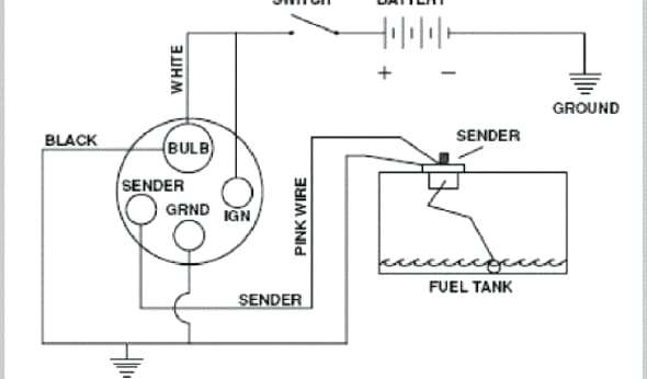
Fuel Cell Sending Unit Wiring Diagram from www.chanish.org To properly read a electrical wiring diagram, one offers to learn how the particular components within the system operate. For example , when a module is powered up and it also sends out a signal of half the voltage in addition to the technician will not know this, he'd think he offers ... Fuel Gauge Sending Unit Wiring Diagram - wiring diagram is a simplified customary pictorial representation of an electrical circuit. It shows the components of the circuit as simplified shapes, and the skill and signal connections amid the devices. A wiring diagram usually gives opinion not quite the relative outlook and arrangement of ... Description: Boat Fuel Sender Wiring Boat Fuel Gauge Sending Unit Wiring with Fuel Sending Unit Wiring Diagram, image size 728 X 476 px, and to view image details please click the image.. Here is a picture gallery about fuel sending unit wiring diagram complete with the description of the image, please find the image you need. Misread diagrams. Looks like one wire on fuel sending unit is to be ground to frame (diagram says blue or purple or light green but I'll use the black one). Another, my guess yellow (although pink on my diagrams) must be circuit 30 to fuel gauge. Leaves the third red wire unaccounted for. It is red, so may be power, but not on my diagrams.
Fuel Sending Unit Help The Hull Truth Boating And Fishing Forum. Fuel gauge and sending unit wiring diagram pour lexus 470 level sensor how to install a moeller kus usa 3 wire the hull 1 0 pcm smiths e troubleshooting ford windstar pump dual station converter for sender 1983 z28 third electrical foxbody issues work on 71 mustang 64 question help truth 87 with tbi not working replaced still ... fuel gauge sending unit wiring diagram - You'll need an extensive, skilled, and easy to comprehend Wiring Diagram. With this sort of an illustrative guide, you are going to be able to troubleshoot, prevent, and complete your tasks without difficulty. Connect (black) wire. from the KUS sending unit to gauge hook-up. If your gauge has color coded hook-ups, maintain this coding as you connect the sender and ground wires. WARNING!! GASOLINE IS EXTREMELY FLAMMABLE. KEEP TANK AREA FREE FROM SPARKS AND FLAMES. EMPTY THE TANKS OF FUEL & FUMES BEFORE CONTINUING WITH INSTALLATION. The fuel tank should be grounded and the sender wire pink should be connected to the sender terminal on the sending unit this is the correct wiring. The sending unit will ground through the mount screws. The fuel gauge reads the resistance to ground check the wires on the back of the gauge pink to S terminal and black to G terminal.
Fuel Sending Unit: I Am Trying to Wire My Front Fuel Pump ...
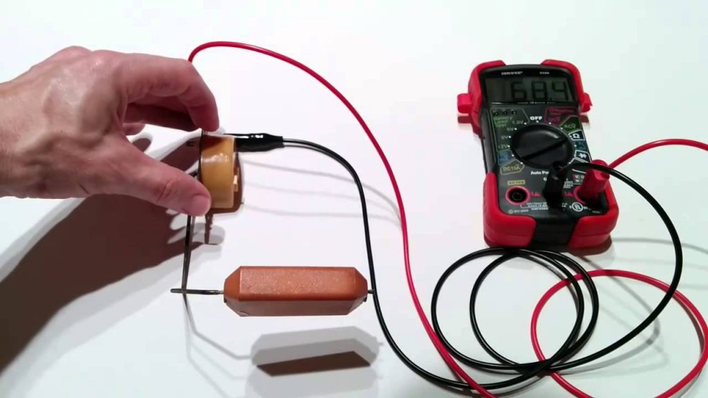
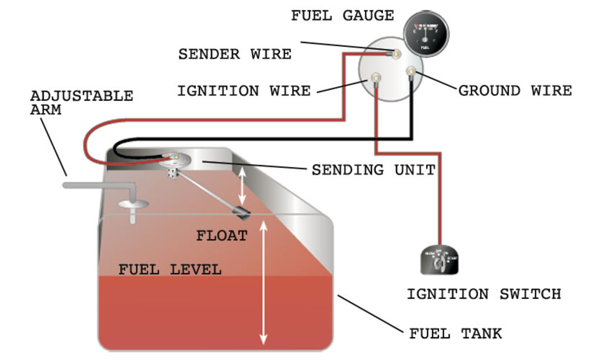
Most fuel gauge problems are either a bad fuel tank sending unit or a bad ground wire going between the sending unit and the frame of the car. The gauge and wiring can be easily tested using only a 12 volt test lamp, once you have access to the wiring at the fuel sending unit.

1990 Ford Diesel Fuel Sending Unit Wiring - Ford Truck ...
Gm Fuel Sending Unit Wiring Diagram. - Welcome to help our blog, on this time period We'll teach you regarding gm fuel sending unit wiring diagram. . And now, this can be a first image: Figure 20 Fuel Tank Sending Unit Removal And Installation Brilliant from gm fuel sending unit wiring diagram , source:blurts.me.
Fuel Sending Unit Wiring Diagram - General Wiring Diagram
Fuel Tank Sending Unit Wiring Diagram from logicdiagram.b2bnetwork.it. Print the electrical wiring diagram off plus use highlighters to be able to trace the signal. When you use your finger or perhaps follow the circuit with your eyes, it is easy to mistrace the circuit. 1 trick that I actually 2 to print exactly the same wiring diagram off twice.
Fuel sending unit wire diagram? - CorvetteForum ...
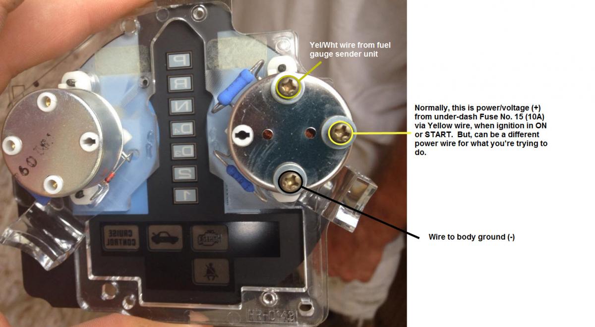
Remove the screws that hold the sending unit to the tank and take it out. Next, remove the three wires on the back of the old gauge. One wire goes to the center pin on the tank sending unit, one goes to ground, and the third connects to a 12-volt source, normally the ignition switch. Remove the fuel gauge.

Fuel Tank Sending Unit Wiring Diagram For Your Needs
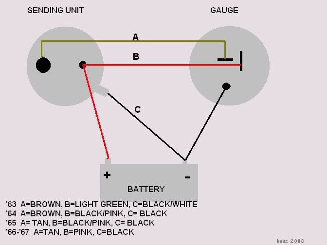
wire system that just has a tan wire from the gauge to the sending unit and a ground at each end of the circuit, and diagnosing problems with this system is quite simple. As background, here's how the "GM Standard" fuel gauge system works (see diagram). Dash Gauge: The dash fuel gauge has two coils in it - the limiting coil on the

2005 Gmc 4500 Wire Diagram For Fuel Sending Unit - Cars ...
Fuel Gauge Sending Unit Wiring Diagram - fuel gauge sending unit wiring diagram, Every electric structure consists of various distinct components. Each component ought to be set and connected with other parts in specific manner. If not, the arrangement won't work as it ought to be.

1994 Dodge Dakota 3.9 V6 Auto 22 gal tank, Ext cab. 2WD ...
wiring instructions. Always disconnect battery ground before making any electrical connections. Parts of the Fuel Level Sender Unit to be Ad Fuel Level Sender Installation: Refer to the VDO catalog for matching fuel gauges. The unit can be adjusted to read accurately in tanks from 6" to 23" deep. Diagram B I. Measure the depth of your fuel tank.
![[DIAGRAM] Fuel Sending Unit Leaking When Tank Full Wiring ...](http://ww2.justanswer.com/uploads/s420/2010-03-05_180201_95_Ranger_fuel_pump_assembly.jpg)
[DIAGRAM] Fuel Sending Unit Leaking When Tank Full Wiring ...
Whats the wiring diagram for the fuel pump on a 85 z28 camaro. The wires should be grey orange and black purple and a black wire. ... Amazon Com Fuel Gas Tank Sending Unit For 85 92 Camaro Firebird 1990 Camaro Wiring Diagram Gas Automotive Wiring Schematic

Figure 20. Fuel tank sending unit, removal and installation.
B5a43 1965 Mustang Fuel Sending Unit Wiring Diagram Digital. Stewart Warner 391a F L Swing 10 15 Fuel Level Sending Unit 240 33 Ohm. Ford Tractor Fuel Sending Unit Wiring Diagram Wiring Diagrams. Testing Fuel Guage Sending Unit Dodge Diesel Diesel Truck.
Ford F150 Fuel Sending Unit Wiring Diagram - Wiring ...
The fuel sending unit is responsible for what the fuel gauge on your vehicle reads. There are two types of sending units; the older float style, which uses a magnet embedded in a float that resides in a tube, sending readings of how high in the tank it is floating, and there is the newer style that measures electrical resistance of the volume of fuel in the tank.
Rci Fuel Cell Sending Unit Wiring Diagram
1973-1977 Monte Carlo Fuel Tank Sending Unit 5/16" Line (2 Outlet - Fuel Sending Unit Wiring Diagram. Wiring Diagram includes each examples and step-by-step instructions that will enable you to definitely actually develop your undertaking. This can be beneficial for both the folks and for specialists who are seeking to find out more on how ...
Boat Fuel Sending Unit Diagram | Manual E-Books ...
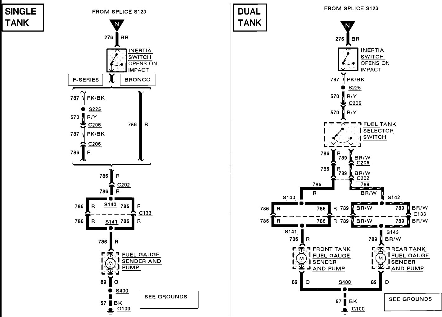
Joined Nov 9, 2020. ·. 2 Posts. #6 · Nov 9, 2020. Patrick Feeley said: Here's the 97 wiring diagram. 94-97 are the same. Note the Diesel diagram only shows two wires for each of the sending units. The gas diagram has an additional two wires shown for each sending unit for the integral pump (which the diesels don't have). Cheers!
fuel gauge wiring with pics? - Honda-Tech - Honda Forum ...
Marine Fuel Gauge Wiring Diagram . March 16, 2019 ... Fuel gauge and sending unit wiring the hull truth smiths e troubleshooting dual units to one engine instrument made easy my doesn t work if it is cell. How To Test And Replace Your Fuel Gauge Sending Unit Sail Magazine
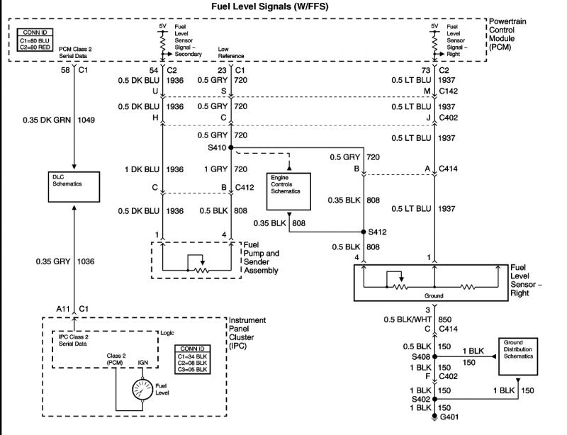
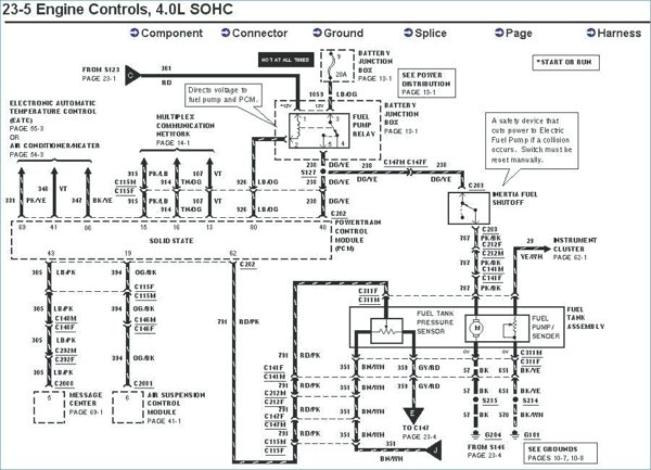
Fuel sending unit wiring diagram to PCM and Instrument ...

Monochrome, Power Lines, Winlaton Mill, Tyne & Wear, England.
64 fuel sending unit wiring question - CorvetteForum ...
1973-1977 Monte Carlo Fuel Tank Sending Unit 5/16" Line (2 ...
![[WA_5967] 78 Ford Fuel Sending Unit Wiring Schematic Wiring](https://static-assets.imageservice.cloud/4288101/1978-1984-all-makes-all-models-parts-fg12f-1978-84.JPG)
[WA_5967] 78 Ford Fuel Sending Unit Wiring Schematic Wiring
Oil Pressure Sending Unit Wiring Diagr | Wiring Library ...

Fuel Gauge Sending Unit Wiring Diagram | Free Wiring Diagram

Fuel gauge and DTE not working on sequoia. fuel sending ...

Autometer Gauge Wiring Diagram Collection
65 El Camino Fuel Sending Unit Wiring Diagram
How to Test and Replace your Fuel Gauge and Sending Unit ...

Gas Tank Level Sending Unit Wiring Diagram For Equus Gas Gauge
72 Nova Fuel Sending Unit Wiring Diagram - Vehicle Wiring ...
Fuel sending unit wiring | Mustang Forums at StangNet
Rci Fuel Cell Sending Unit Wiring Diagram

78 Ford Fuel Sending Unit Wiring - Wiring Diagram Networks
Fuel sending unit wire diagram? - CorvetteForum ...

Fuel Level Sending Unit
wiring Question for Fuel tank - Dodge Diesel - Diesel ...
1993 Jeep Wrangler Fuel Sending Unit Wiring: I Broke My ...

Wiring Diagram 94 Camaro Z28 Fuel Gauge Sending Unit In Tank

1988 Saab 900 Turbo Fuel Sending Unit Wiring Diagram
1990 Ford Diesel Fuel Sending Unit Wiring - Ford Truck ...
Rci Fuel Cell Sending Unit Wiring Diagram
Fuel sending unit wire diagram? - CorvetteForum ...

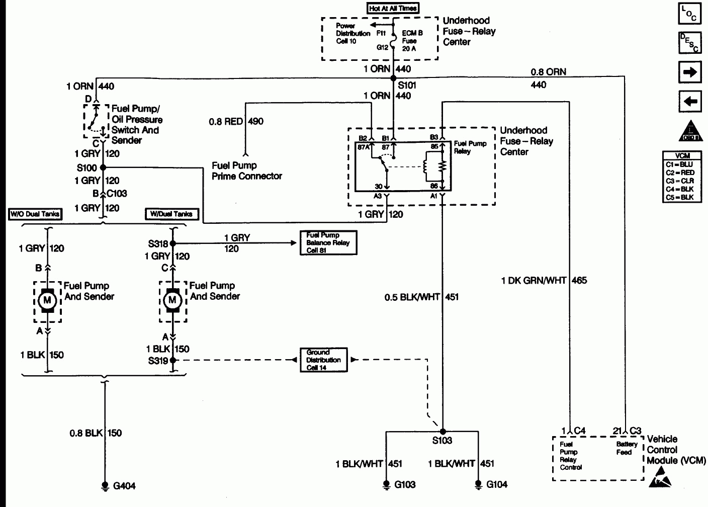
Need wiring diagram for 1988 chevy s10 pickup.Fuse ECM ...

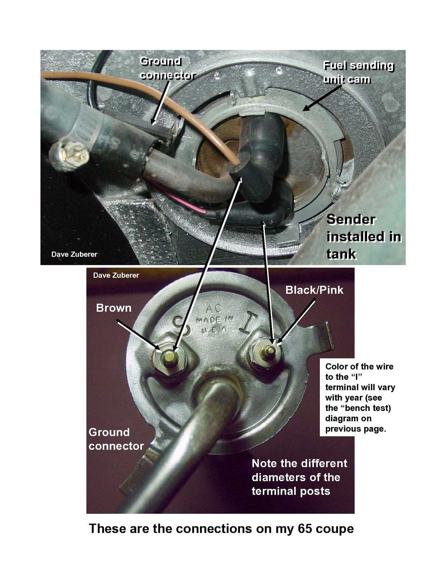
65 Fuel Guage problem - Ford Mustang Forum
0 Response to "40 fuel sending unit wiring diagram"
Post a Comment