39 kenworth clutch linkage diagram
I have a 2006 Kenworth T800B. The clutch linkage from the pedal to the first pivot point has snapped at the joint that attaches up at the pedal. I have the part removed except for the piece that looks like was screwed directly into the pedal assembly. My questions is how do I access this piece for the clutch pedal assembly. Jan 27, 2009 · I like the linkage on my '66, its aeroquip hose (air clutch!). Here is a print of the pedal assembly inside the cab. The rod ends according to KW are typically 3/8" SAE female threads, with a 5/16" SAE thread stud sticking out. KW's number for the rod ends is K124-122, and there should be a total of 4.
Extrapolated over the 13 re-adjustments a manual-adjust clutch will typically require, the maintenance savings alone can be significant. And that's assuming an operator is taking the vehicle in for a clutch adjustment whenever it's needed - something that's trickier to do when a hydraulic linkage is paired with a manual-adjust clutch.

Kenworth clutch linkage diagram
204. Dec 3, 2011. n.h. 0. The clutch adjustment should be set at 1/2 to9/16 gap between the release bearing & the clutch brake. Set this with the internal adjuster then adjust the external linkage if needed. ALWAYS set the internal gap 1st. pup, Dec 25, 2011. pup, Dec 25, 2011. That's why most home mechanics rely on a Jeep CJ7 clutch linkage diagram to guide them throughout the process. Using this simple map, you can locate and test each and every part of your clutch system to identify the origin of your current issues and get them fixed as soon as possible. Early models have a bolt and lock. Remove lock and turn ring to adjust clutch. Proper adjustment will be achieved when you have 3/8"-1/2" clearance between the clutch brake disc and the clutch ...
Kenworth clutch linkage diagram. Parts Availability. Count on the Kenworth Parts Network to get you back in business quickly. With a full range of parts in stock and access to our coast to coast network of distribution centers, we can deliver the parts you need within 24 hours. Learn More. Mechanics must be familiar with proper clutch adjustment, linkage adjustment, lubrication and other maintenance troubleshooting procedures out-lined in the Failure Analysis Guide. When disassembling various assemblies, lay all parts on a clean bench in the same sequen ce as removed to simplify and measuring clutch pedal and clutch specs on throwout bearing to clutch brake, and shift fork to throwout bearing Shift linkage installation ..... 51 1. 2. Group 41 Hydraulically Actuated Clutch About this Service Information General About this Service Information The information and instructions contained in this Service Information pertain to the ... Clutch Fluid ..... DOT 4 (SAE J1703) Fluid Reservoir Capacity ..... 0.15 liter (0.16 qts.) ...
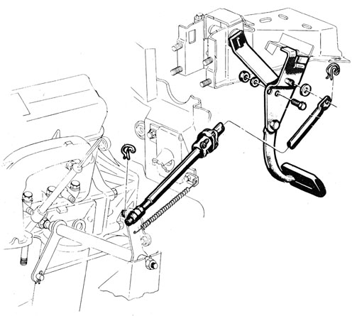
You will have (going from memory as I owned a 2000 Peterbilt 379L about 15-17yrs ago): 1 or 2 on each brake s-cam tube (each wheel) 1 on each brake slack adjuster (each wheel) 2 front leaf spring shackle pins (rear of front leaf) each side. 1 front spring pin (front of front leaf spring, right behind bumper)each side. The clutch just needs to be adjusted. You need to make the bottom adjustment through the inspection hole first to obtain a 1/2" gap between the throw out bearing and clutch brake. After that adjustment is made and the 1/2" gap is correct then check your pedal free travel and you should have 1 1/2" to 2". I like the linkage on my '66, its aeroquip hose (air clutch!). Here is a print of the pedal assembly inside the cab. The rod ends according to KW are typically 3/8" SAE female threads, with a 5/16" SAE thread stud sticking out. KW's number for the rod ends is K124-122, and there should be a total of 4. T 600 Kenworth Clutch Linkage Diagram List Of Schematic Circuit Kenworth hvac systems b7807 2000 kenworth w900 wiring diagram schematic digital resources 1991 kenworth last 6 of vin575320 looking for a c wiring diagram 2007 kenworth t600 wiring schematics most exciting diagram.
Nov 26, 2007 · Follow that linkage, to the next lever/arm (thats where I attached the bungee cord and pulled it aft, to a place to attach it. I dont know about your model truck, but my truck, when they got around to putting the spring on it, went from the clutch arm to a bracket aft of the tranny area. kenworth-clutch-linkage-diagram-bjpics 1/1 Downloaded from hydrogen.iges.jp on November 21, 2021 by guest [Book] Kenworth Clutch Linkage Diagram Bjpics Recognizing the habit ways to get this ebook kenworth clutch linkage diagram bjpics is additionally useful. You have remained in right site to The Kenworth Privileges card connects you to the special deals and discounts you need. SIGN UP NOW. Over-The-Air Updates. Over-The-Air is a software update system that helps you keep your trucks running with the latest engine software version - safely and securely over-the-air. Find a dealer Search Location. Clutch Linkage Components 1 2 LAST 1060-72 CHEVY/GMC CLUTCH FORK BOOT: Item #: CBC6072: $12.99: 1960-72 CHEVY/GMC CLUTCH ROD BOOT: Item #: CRB0720: $14.99: 1967-72 CHEVY/GMC AUTO TRANS LINKAGE COUPLER ...
A gearshift linkage for a cab-over-engine type truck having a shift lever extending up through the cab floor enables the forward tilting of the cab on the frame, about the cab pivot axis, without disengagement of the shift linkage and without dislocation of the shift lever from the cab. In the preferred embodiment, a conventional shifter control unit is secured to the cab just below the floor ...
kenworth-clutch-linkage-diagram-bjpics 1/1 Downloaded from db.naboovalley.com on November 30, 2021 by guest [Books] Kenworth Clutch Linkage Diagram Bjpics Yeah, reviewing a ebook kenworth clutch linkage diagram bjpics could amass your close contacts listings. This is just one of the solutions for you to be successful.
Hi there, Save hours of searching online or wasting money on unnecessary repairs by talking to a 6YA Expert who can help you resolve this.in addition 4l60e transmission wiring diagram sevimliler in addition taotao 50cc scooter wiring diagram in addition bmw rrt fuse box together with kenworth clutch linkage diagram furthermore fuse box layout k ...
Kenworth Clutch Brake Adjustment 1996 Kenworth Clutch Brake Adjustment Kenworth Clutch Linkage Diagram Kenworth T800 Clutch Brake Adjustment 1 2 3 Related searches for kenworth clutch brake linkage adjustment How to Adjust a Clutch Linkage on a Kenworth T 600 | eHow www.ehow.com › … › Car Maintenance › Do It Yourself Car Maintenance
with alot of cussin & tearin out most all of the l.h. kick panels to get your hand up inside the steerin colume brackets to find ya can't undo the top of the spring. get the longest pair of needle ...
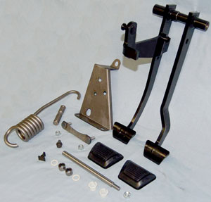
Clutch Linkage Assembly. In Stock. Part# E17-6002-001 OLD# -. Clutch Linkage Assembly. $272.29. Skip to the end of the images gallery. Skip to the beginning of the images gallery. Description.
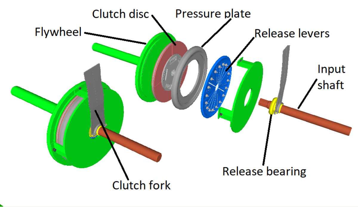
The clutch linkage connects the driver to the clutch assembly, transforming foot motion that depresses and releases the clutch pedal into clutch disengagement and engagement. There are 2 types of clutch linkage, hydraulic and mechanical, and 2 types of mechanical linkage, cable and pushrod, also called shaft and lever.
Kenworth K124-305 Clutch Installation Parts - NEW. Item: SS S-23260. Clutch linkage swivel. 34.60 $. Add To Cart.
Order parts that fit your make, model and application in "real-time" from the convenience of your desktop, laptop, or tablet computer. Check inventory and confirm pricing. Search TRP Catalog parts easily. Upload spreadsheet orders. View your saved orders and history.
2007 Kenworth W900 Wiring Diagram. Kenworth T600 Air Conditioner Condenser Oem K122104 In Stockton. C9a7 2007 Kenworth T800 Wiring Schematic Resources. See also Beef Stroganoff With Ground Recipe. Kenworth Hvac Systems. Kenworth Clutch Linkage Arm Rod Assembly T800 W900 K037 153 K186. Ab1 Kenworth W900 Wiring Schematic Diagrams Resources.
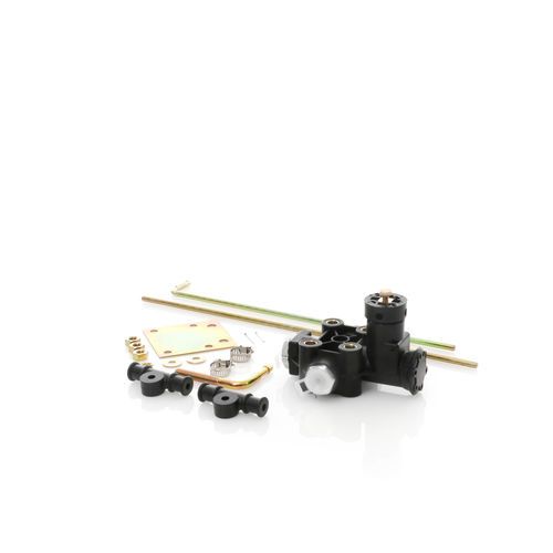
Find many great new & used options and get the best deals for Kenworth Clutch Linkage Arm Rod Assembly T800 W900 K037-153 K186-2341 at the best online prices at eBay! Free shipping for many products!
Clutch 308925-82. Clutch Eaton 308925-82. Eaton Fuller 15-1/2 in. (380mm) Pull-Type Easy Pedal 2000 2 in. Spline 7 Spring 4 Ceramic Super Button Mack Clutch Set
[DOC] Kenworth Clutch Linkage Diagram Bjpics When somebody should go to the ebook stores, search opening by shop, shelf by shelf, it is essentially problematic. This is why we give the book compilations in this website. It will definitely ease you to look guide kenworth clutch linkage diagram bjpics as you such as.
Elite Truck Parts. Elite Truck Parts Clutch Rod End, Lh - Kenworth ID: ETP-K124-402-1. ETP-K124-402-1. $42.98. Add to Cart. This item ships in 3-5 business days.
kenworth-clutch-linkage-diagram-bjpics 1/1 Downloaded from dev.endhomelessness.org on November 16, 2021 by guest Download Kenworth Clutch Linkage Diagram Bjpics If you ally dependence such a referred kenworth clutch linkage diagram bjpics books that will give you worth, acquire the totally best seller from us currently from several preferred ...
7. 0. Nov 10, 2017. 0. I am working on a 2007 W900 Kenworth and going to replace the linkage from the clutch pedal down to the other linkage and replace the ball joints on the other linkage. Just wondering what is the best way to get at them. The reason I am changing them is the clutch pedal wont return to home position, was told that this ...
Get exclusive offers from Kenworth in your inbox. Save on a wide selection of replacement parts and expert service. Sign up now! Be the first to know about exclusive savings. Sign up now. Thank you for signing up for Kenworth Parts & Service. You've entered an invalid email address. Please try again.
Step 7. Hold the handle of the clutch adjustment tool back toward the rear of the bell housing. Engage the tip of the tool between the bolt head and the notch on the clutch plate. Turn the clutch clockwise to adjust the clutch. Make one complete turn of the clutch with the tool and then check the free travel of the clutch pedal.
Early models have a bolt and lock. Remove lock and turn ring to adjust clutch. Proper adjustment will be achieved when you have 3/8"-1/2" clearance between the clutch brake disc and the clutch ...
That's why most home mechanics rely on a Jeep CJ7 clutch linkage diagram to guide them throughout the process. Using this simple map, you can locate and test each and every part of your clutch system to identify the origin of your current issues and get them fixed as soon as possible.
204. Dec 3, 2011. n.h. 0. The clutch adjustment should be set at 1/2 to9/16 gap between the release bearing & the clutch brake. Set this with the internal adjuster then adjust the external linkage if needed. ALWAYS set the internal gap 1st. pup, Dec 25, 2011. pup, Dec 25, 2011.











0 Response to "39 kenworth clutch linkage diagram"
Post a Comment