37 shear force and bending moment diagram solved examples
Static friction free body diagram. Free-body diagram s are diagram s used to show the rel at ive magnitude and direction of all forces acting upon an object in a given situ at ion. A free-body diagram is a special example of the vector diagram s th at were d is cussed in an earlier unit. The se diagram s will be used throughout our study of ... Draw shear force and bending moment diagram. Calculate the shear force and bending moment for the beam subjected to an uniformly distributed load as shown in the figure, then draw the shear force diagram (SFD) and bending moment diagram (BMD). 5 kN/m 3 m A B EXAMPLE 6 If we have bending moment diagram then just by differentiating the shear at ...
Reinforced Concrete Design Theory and Examples. × Close Log In. Log in with Facebook Log in with Google. or. Email. Password. Remember me on this computer. or reset password. Enter the email address you signed up with and we'll email you a reset link. Need an account? Click here to sign up. Log In Sign Up. Log In; Sign Up ...
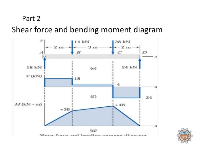
Shear force and bending moment diagram solved examples
Problem 4.5-3 Draw the shear-for ce and bending-moment diagram s.26 pages. Draw the shear diagram for the beam. assume that m0=200lb⋅ft, and l=20ft. Transcribed image text: Problem 6.13 Part A Draw the shear diagram for the beam. Assume that Mo 200 lb.ft, and L 20 ft. Begin by placing the lines of discontinuity. Aug 23, 2021 · Shearing force and bending moment diagram. To determine the magnitudes of the shearing force and the bending moment and draw their diagrams, apply the obtained redundant to the primary beam, as shown in Figure 10.4e. The shearing force and the bending moment diagrams are shown in Figure 10.4h and Figure 10.4i. Variation of shear force and bending moment diagram s S.N Point Load UDL UVL Shear Force Constant Linear Parabolic Bending Moment Linear parabolic Cubic WORKED EXAMPLES 1) A cantilever beam of length 2 m carries the point load s as shown in Fig. Draw the shear force and B.M. diagram s for the cantilever beam.
Shear force and bending moment diagram solved examples. Trapezoidal distributed load shear and moment diagram [email protected] w12 5w | 4 384El x) M max. 8kN329 6 1 Draw The Shear And Moment Diagrams For Aerostudents. 5 Shear-Force and Bending-Moment Diagrams 275. The cantilever beam is one of the most simple structures. Method of the Integrals. 1500 Mar 18, 2021 · Add Trapezoidal Load. Solution ... Bending Moment And Shear Force Diagram Calculator The First Easy To Use Customizable For Simply Supported Beams. Determine The Shear Force V And Bending Moment M At Midpoint Of Beam With Overhangs See Figure Note That One Load Acts Downward Other Upward Clockwise Moment s. Chapter 4 Shear Forces And Bending Moment Studocu. Boundary condition: Diagram s: fixed-fixed beam. Shear force at a cross section of beam is the sum of all the vertical forces either at the left side or at the right side of that cross section.. Bending moment at a cross section of beam is the sum of all the moments either at the left side or at the right side of that cross section.. Types of Rigid Supports. Simple Supports. Roller Support; Hinge Support (or) Pin Support Genre: eLearning | MP4 | Video: h264, 1280x720 | Audio: AAC, 48.0 KHz Language: English | Size: 2.19 GB | Duration: 9h 25mLearn structural analysis/ statics of civil engineering structures : Truss, Beam and Frame with practical examples. What you'll learn Concept of Force and Moment Basic...
Bmd bending moment diagram. For each beam shown draw the free body diagram and discuss the support reactions present. The cantilever is a beam which has one end free and the other is fixed. The following is the process for determining the reaction at the wall for a cantilever beam. And we have 14 inches from the point a to the right hand side. Apr 13, 2017 · Draw the diagrams of maximum bending moment and shear force. 15.What is meant by maximum shear force diagram in influence line? Due to a given system of rolling loads the maximum shear force for every section of the girder can be worked out by placing the loads in appropriate positions. STRUCTURAL ANALYSIS IN SPREADSHEET First of all we solved the problems of various members such as beam, truss and frame by using stiffness method in3-8 Continuous beam (II) 3-9 Concluding remarks Exercises III Chapter 4 PLANE TRUSS 4-1 General 4-2 Stiffness matrix of a member 4-3 Joint equilibrium equations 4-4 Member force 4-5 Examples 4-6 ... This program calculates the shear force and bending moment profiles, draw. the free body, shear force and bending moment diagrams of the problem. Under the free body diagram, the equations of each section is clearly. written with Latex. To use this program, you call the function placing the arguments in cells.
Academia.edu is a platform for academics to share research papers. Beams: Bending moment and shear force diagram, bending stresses and deflection of beam. CIVIL III STRENGTH OF MATERIALS 10CV33 NOTES Contact is one of the common positions for relationship existing between surfaces of mechanical components with line or point shape, which lead to different stress condition between them. Apr 17, 2021 · The bending moment is a reaction in a structural element that is subjected to an external force or moment, causing bending. Beams are a structural element, which are associated with bending moment diagrams and analysis.. When a load is applied to the beam which is large in magnitude, failure of the beam can occur. The three internal forces at the section are the axial force, N Q, the radial shear force, V Q, and the bending moment, M Q. The derivation of the equations for the determination of these forces with respect to the angle φ are as follows: Fig. 6.2. Three – hinged arch. Bending moment at point Q. where = moment of a beam of the same span as ...
Biblioteca en línea. Materiales de aprendizaje gratuitos. 1000 Solved Problems in Classical Physics Ahmad A. Kamal 1000 Solved Problems in Classical Physics An Exercise Book 123 Dr. Ahmad A. Kamal Silversprings Lane 425 75094 Murphy Texas USA [email protected][email protected]
They are composed of planar, bending- and shear-resistant shell elements and present an ideal situation for the constructional use of glass. The ridge-and-furrow principle developed by the English greenhouse pioneer J. C. Loudon and used to great success by J. Paxton with his Crystal Palace in 1851 is an early example of folded glass roof ...
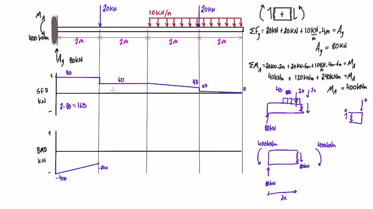
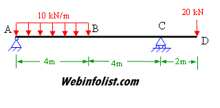
Calculating Shear Force Diagram - Step 2: Keep moving across the beam, stopping at every load that acts on the beam. When you get to a load, add to the Shear Force Diagram by the amount of the force. In this case we have come to a negative 20kN force, so we will minus 20kN from the existing 10kN. i.e. 10kN - 20kN = -10kN.
For example, users require to automate some aspects of Excel, such as repetitive tasks, frequent tasks, generating reports, etc. The user can create a VBA program (macro) within Excel that generates, that can generate shear force diagram, bending moment diagram, autocad drawings etc. 2.

Triangular Distributed Load Shear And Moment Diagram 16012019 16012019 6 Comments on Triangular Distributed Load Shear And Moment Diagram The first part of being able to calculate a beam problem is to be able to calculate the shear and moment diagrams and. W 60 x2Nm 240 Nm. R F 1 F 2 1320 2010.
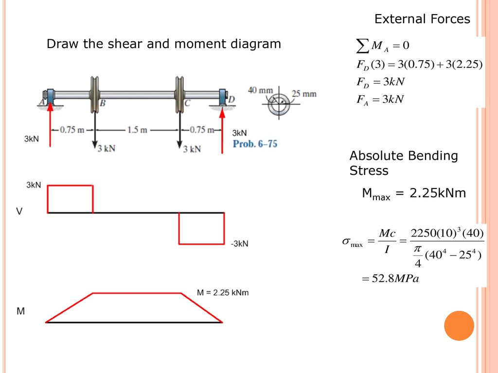
Construct The Shear Force And Bending Moment Diagrams For Beam Below Determine A Max B Location Of. Solved if the beam shown in figure is subjected to an internal bending moment of m 50 kn 15 mm determine maximum stress th course hero mechanics of materials bending normal stress slender structures boston if the beam is subjected to an internal ...
Solved Question 1 Portal Frames 20 Figure Shows A Chegg Com ... Frame Analysis Example 2 Part 1 Shear And Moment Diagrams Structural You ... pfh structural engineering general discussion eng tips beamguru com beam calculator and frame truss online draws bending moment shear force axial.

Aug 01, 2019 · 5.7 Normal and Shear Stresses. When a beam is bent by transverse loads, usually both a bending moment M and a shear force V act on each cross section. The distribution of the normal stress associated with the bending moment is given by the flexure formula, Eq.

Bending moment diagram (bmd) shear force diagram (sfd) axial force diagram. Sfd and bmd for a simple beam with a uniform load. Get the unknown sf and bm. Solved Draw The Bending Moment Diagram Bmd And The Sh Chegg Com from d2vlcm61l7u1fs.cloudfront.net Shear force and bending moment diagrams sfd & bmd. The calculator is fully customisable.

dubaiburjkhalifas. Images may be subject to copyright Lean More. Shear Force Bending Moment In Matlab Youtube. M = moment (x,order,vecdim) returns the central moment over the dimensions specified in the vector vecdim. for example, if x is a 2 by 3 by 4 array, then moment (x,1, [1 2]) returns a 1 by 1 by 4 array. each element of the output array ...

The influence of a certain force (or moment) in a structure is given by (i.e.it is equal to) the deflected shape of the structure in the absence of that force (or moment) and when given a corresponding unit displacement (or rotation) . Müller -Breslau Principle Example : Examples: ForceMethod Page 17
Therefore, a joint can be solved when there are one or two unknowns forces and at least one known force acting on it. Forces are transferred from joint to joint by the connecting members, so when unknown forces on a joint are found, the corresponding forces on adjacent joints are …
Draw the shear diagram for the beam. assume that m0=200lb⋅ft, and l=20ft.. Draw the shear diagram for the beam. Assume that M0=200lb⋅ft, and L=20ft. Begin by placing the lines of discontinuity. Place the appropriate function between the lines of discontinuity, ensuring the endpoints have the correct values. Note - Make sure you place only ...
Axial Force Shear And Bending Moment Diagrams Of Frames. reza November 26, 2021. Axial force shear axial force solved draw the shear bending moment 21 b example 18 for the given frame. The Free Body Diagram Of Frame Figures 2 29 And 30 Is Shown In Figure 3 18 Includes Four Reactions Determined Worked Example 5 Draw Axial Force Shear.

6) The reading was recorded. 7) Convert the mass in to load in (N) and the force reading in to a bending moment (Nm) . Bending moment at the cut in [Nm] = Displayed force X 0.125 RESULT : Mass (g) Load (N) Force (N) Problem 10: Bending Moment and Shear force A beam with a hinge is loaded as above. Draw the shear force and bending moment diagram.

Shear force and bending moment diagram of simply supported beam can be drawn by first calculating value . Being able to draw shear force diagrams (sfd) and bending moment diagrams (bmd) is a critical skill for any student studying statics, . Force and bending moment along the length of the beam. Shear force and bending moments.
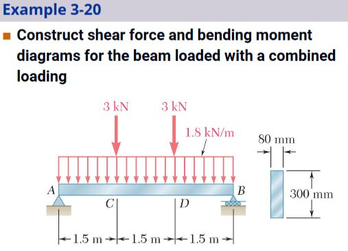
Total downwards load due the u. Shear and Moment Diagrams. We want to draw the necessary diagrams using the area method. Draw the Shear Force Diagram. bending and shear stresses for the beam SKN 10KN/m 12 KN/m B + Im 3m 2m 3m… 1] Draw the shear force and bending moment diagrams for the beam shown below.
Draw shear force and bending moment diagram. Calculate the shear force and bending moment for the beam subjected to an uniformly distributed load as shown in the figure, then draw the shear force diagram (SFD) and bending moment diagram (BMD). 5 kN/m 3 m A B EXAMPLE 6 If we have bending moment diagram then just by differentiating the shear at ...
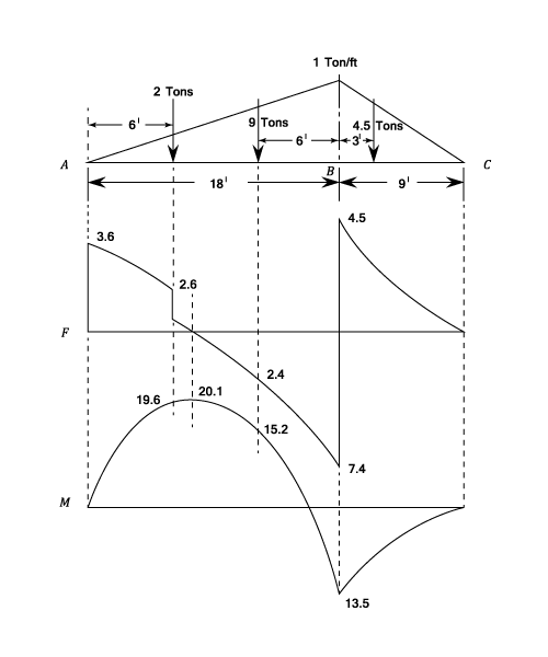
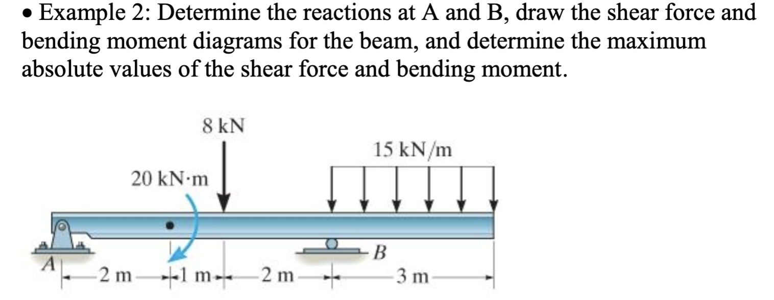
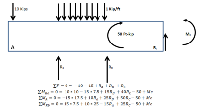
Example 1. A simply supported beam is loaded as shown in the diagram. Calculate the support reactions and draw the Bending Moment diagram, Shear Force Diagram, Axial Force Diagram. Determine the maximum bending moment.

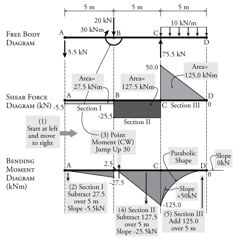
4.0 Building Shear and Moment Diagram s. In the last section we worked out how to evaluate the internal shear force and bending moment at a discrete location using imaginary cuts. But to draw a shear force and bending moment diagram, we need to know how these values change across the structure.Actions. Clear All Download Inputs File Upload from File Load Example Download Report.
Figure 1. / Mechanics of Materials 97 (2016) 48–58 49 conditions, which was dependent on the stress level (Kang et al. The lien exists for both real property and personal property. Determine the section’s moment of inertia Determine the maximum shear force V that the strut can support if the allowable stress for the material is allow = 50 ...
A shear diagram shows the shear force along the length of the beam, and a moment diagram shows the bending moment along the length of the beam. Shear And Moment Diagrams S B A Invent October 28, 2020 - Beast Academy is advanced math curriculum for your child at home.
Nov 02, 2017 · Bending moment diagram 20. ... Shear force diagram Fig.5.7. Displacement diagram ... Inclined planes are widely used to move heavy loads over vertical obstacles; examples vary from a ramp used to load goods into a truck, to a person walking up a pedestrian ramp, to an automobile or railroad train climbing a grade. ...

with tables) Chapter 10-Force Method for Beams Force method example #1: one degree indeterminate Shear force and bending moment diagram practice problem #1 Solving for Fixed End Moments of Beams (FEM Table Included) SA60: The Three-Moment Equation for the Analysis of Continuous Beams (Part I)beam deflection double integral-1
1. Determine the moment of a force of 25 N applied to a spanner at an effective length of 180 mm Calculate reactions, deflection, moments and shear forces in simply supported and cantilever beams. Reinforced Concrete Design Examples, Example 1 - Checking Shear Adequacy and Designing Shear Reinforcement for Simply Supported Beam.
Solved Calculate The Maximum Shear Stress Tau Max And Bending 1 Transtutors. How to calculate the maximum bending moment from a shear force diagram quora construct the shear force and bending moment diagrams for beam below determine a max b location of for beam ab a draw the shear stress and bending moments diagrams b determine location ...

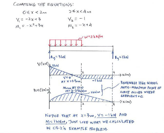
Finally calculating the moments can be done in the following steps: 2. From left to right, make "cuts" before and after each reaction/load. To calculate the bending moment of a beam, we must work in the same way we did for the Shear Force Diagram. Starting at x = 0 we will move across the beam and calculate the bending moment at each point.
Variation of shear force and bending moment diagram s S.N Point Load UDL UVL Shear Force Constant Linear Parabolic Bending Moment Linear parabolic Cubic WORKED EXAMPLES 1) A cantilever beam of length 2 m carries the point load s as shown in Fig. Draw the shear force and B.M. diagram s for the cantilever beam.

Aug 23, 2021 · Shearing force and bending moment diagram. To determine the magnitudes of the shearing force and the bending moment and draw their diagrams, apply the obtained redundant to the primary beam, as shown in Figure 10.4e. The shearing force and the bending moment diagrams are shown in Figure 10.4h and Figure 10.4i.

Problem 4.5-3 Draw the shear-for ce and bending-moment diagram s.26 pages. Draw the shear diagram for the beam. assume that m0=200lb⋅ft, and l=20ft. Transcribed image text: Problem 6.13 Part A Draw the shear diagram for the beam. Assume that Mo 200 lb.ft, and L 20 ft. Begin by placing the lines of discontinuity.


0 Response to "37 shear force and bending moment diagram solved examples"
Post a Comment