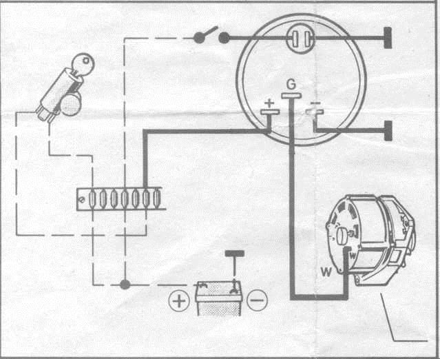
41 faria tachometer wiring diagram
For more information about the installation of and instructions on how to use our gauges we invite you to check out our website at www.FariaBeede.com/manuals.40 pages Diagram faria gauges wiring full version hd quality tachometer images nomor siapa beede fuel gauge with etec remote the hull truth boating and fishing forum installation instructions is0329 manualzz 29 niche analog kit replaces 2003 2005 gateway system plus supplementary for 2006 2007 mode magnetic proximity cruisers sailing photo gallery vdo boat marine instrumentation guide volume 1 ...
View wiring diagrams and schematics for hundreds of popular boats including Lowe, Larson, Alumacraft, Lund, and others. Files are fully down-loadable . Apr 08, · Re: Faria tach gauge wiring. The standard side mount remote control will have a three wire plug below the ignition switch for the the three wire tachometer harness.

Faria tachometer wiring diagram
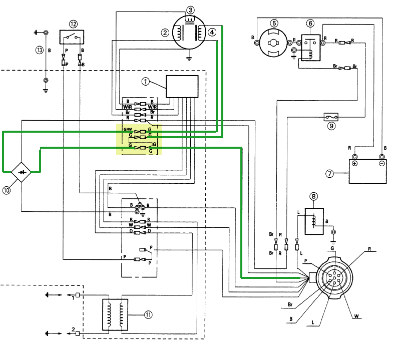
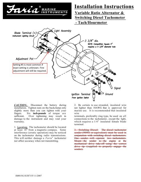
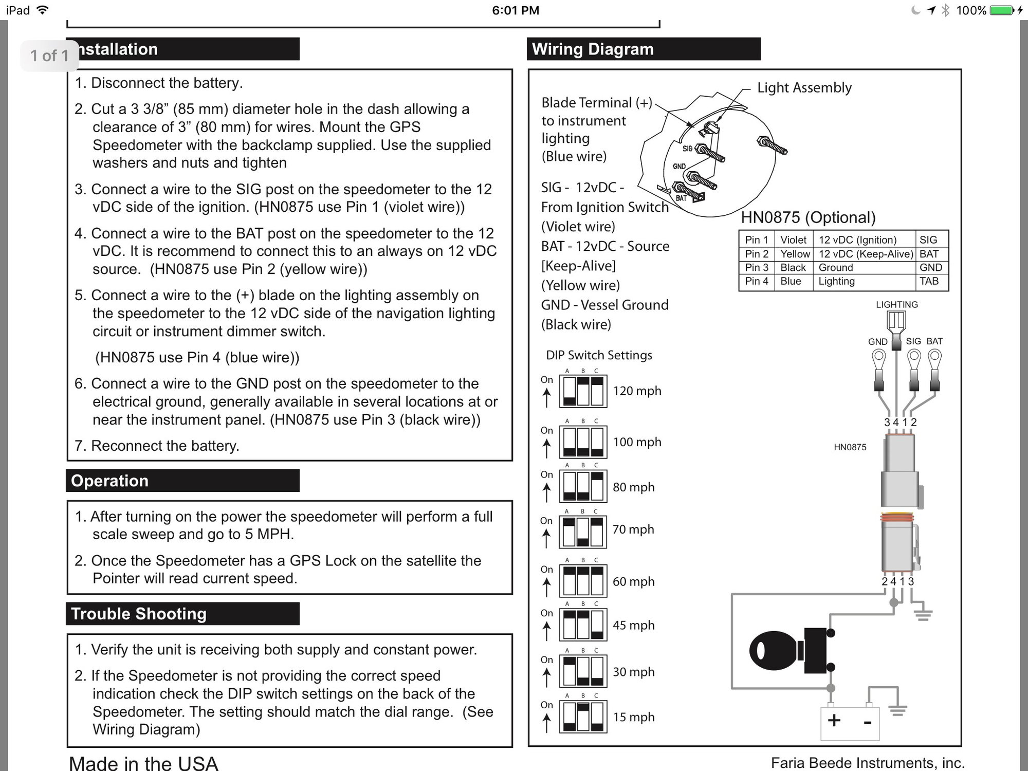
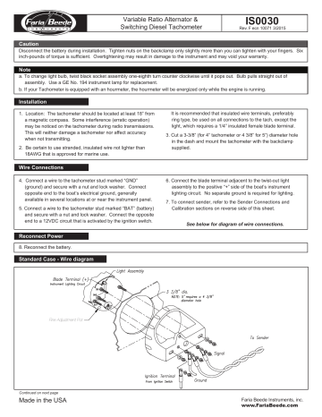
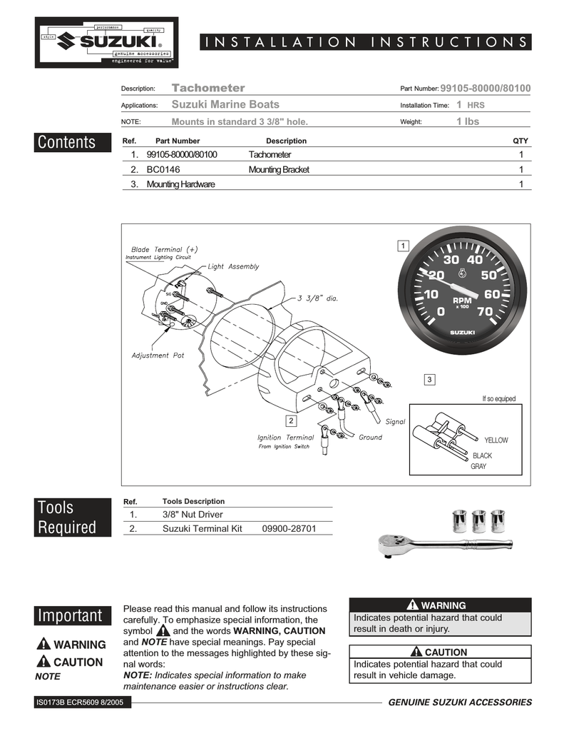
For technical assistance, contact Faria Beede Instruments - Customer Service between 8:30 AM and 5:30 PM Eastern time weekdays at (860) 848-9271 or (800) 473-2742. 3-3/8” dia. Notch Deutsch Connector Case IS0012 Standard Case - Wire diagram Connectorized Case - Wire diagram Fine Adjustment Pot IS0015, Tachometer - Diesel - Variable Ratio Alternator, Installation ... IS0398, FB-Sentry - WD300 - Wiring Diagram, Wiring Diagram. IS0399, Speedometer ... This will neither damage a Faria® tachometer nor affect accuracy when not transmitting. 2. Be certain to use stranded, insulated wire not lighter than 18AWG that is approved for marine use. It is recommended that insulated wire terminals, preferably ring type, be used on all connections to the tachometer, except the light,
Faria tachometer wiring diagram. Non destructive way to fix a common issue with these boat tachometers. Like and share. Thanks! ;-) FariaBeede.com ... by the Tachometer by attaching the analog trim wires from the engine to the back of the ... 7, 8) [See Wire Diagram on the next page].2 pages HN0355. 3. Large Connector Socket. Tachometer with Fuel Flow. Follow the wiring diagram at the end of this manual for wiring connections ...22 pages Speedometer Operations. Installation Instructions. 6. If Required - Connect the (Yellow) wire from pin 2/B to an external button.4 pages
If the number of poles is not known, consult the “Outboard Tachometer Application” chart or call Faria® Marine Instruments at. (860) 848-9271 with make, model, ...3 pages This will neither damage a Faria® tachometer nor affect accuracy when not transmitting. 2. Be certain to use stranded, insulated wire.2 pages View wiring diagrams and schematics for hundreds of popular boats including Lowe, Larson. If you have determined that the Faria Gateway box is defective, there is no direct replacement for Insert PP tach wire in the 2way connector supplied with the new Check for proper locations of gauge's ring terminals according to schematic. IS, A, FB-Sentry ... Faria Tachometer Wiring Diagram Source: i0.wp.com. Read electrical wiring diagrams from negative to positive plus redraw the signal as a straight collection. All circuits usually are the same – voltage, ground, individual component, and switches. Faria Tachometer Wiring Diagram Source: www.marineengine.com.
Figure 4 Tachometer Set-Up. Table 1 Tachometer Selection Table. Table 2 Fuel Sender Selection Table. HNO358 SystemCheck Wire Diagram.18 pages Apr 08, · Re: Faria tach gauge wiring. The standard side mount remote control will have a three wire plug below the ignition switch for the the three wire tachometer harness. Connect the blue lighting wire to one of the other blue lighting wires on a nearby gauge. Faria Synchronizer greatly simplifies the task of controlling the engine ... Faria beede fuel gauge wiring with etec remote the hull truth boating and fishing forum tachometer diagram images nomor siapa is0329 manualzz 2020 f70 la needed help controlling a resistive analog project guidance arduino installation instructions pdf pdf4pro yamaha trim sender ribnet forums llv dash gauges sema data co op smartcraft alarm ambient temperature ckt hi 2005 searay… Read More » This will neither damage a Faria® tachometer nor affect accuracy when not transmitting. 2. Be certain to use stranded, insulated wire not lighter than 18AWG that is approved for marine use. It is recommended that insulated wire terminals, preferably ring type, be used on all connections to the tachometer, except the light,
Wiring Problems Tachometer Mustang 73 Page 2 Introductions 7173mustangs Com
IS0015, Tachometer - Diesel - Variable Ratio Alternator, Installation ... IS0398, FB-Sentry - WD300 - Wiring Diagram, Wiring Diagram. IS0399, Speedometer ...

Installing Faria Gps Speedometer In 2009 212x Jetboaters Net The World S Largest Jet Boat Forum
For technical assistance, contact Faria Beede Instruments - Customer Service between 8:30 AM and 5:30 PM Eastern time weekdays at (860) 848-9271 or (800) 473-2742. 3-3/8” dia. Notch Deutsch Connector Case IS0012 Standard Case - Wire diagram Connectorized Case - Wire diagram Fine Adjustment Pot
Tach Install On 93 C40plrr Yamaha Outboard Parts Forum
1

Installing Faria Gps Speedometer In 2009 212x Jetboaters Net The World S Largest Jet Boat Forum
Instructions For Installing Calibrating Amp Troubleshooting

Johnson Outboard Tach Wiring Diagram Johnson Outboard Ignition Switch Wiring Diagram
First Boat Project And First Time Boat Owner All In One Long Post Boat Design Net
Tadiesels Com
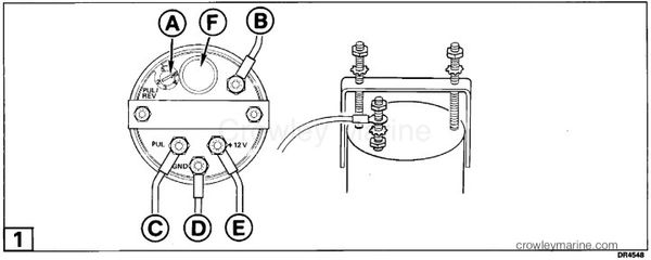
Installation Instructions Tachometer Kit Crowley Marine

Faria Boat Tach Wiring Basic Electronics Wiring Diagram Pdf

Faria Gauge Piifaria Fuel Gauge Tachometer Water Pressure Gauge Trim Meter Hour Meter Volt Meter Tachometer Selector Switch Setting Using A Small Screwdriver Pdf Document
Yanmar Tacho Query Cruisers Sailing Forums
Tadiesels Com

990c0 80001 Suzuki 4 Tachometer Precision Marine
Faria Gps Speedometer Wiring Question The Hull Truth Boating And Fishing Forum
Magnetic Pick Up Tachometer Installation Manualzz
Troubleshooting Boat Gauges Instruments And Meters Boatus

Two Wire Faria Tach In 65 Vintage Mustang Forums
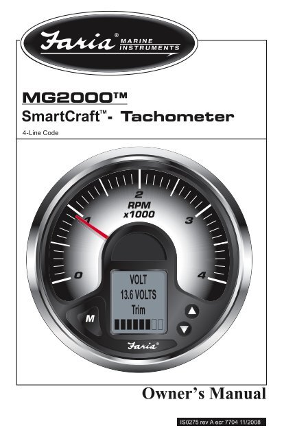
Mg2000 Smartcraft Faria Instruments
Connecting An Alternator To An Albacombi Calibration Albacombi Nmea2000 Converter

Smartcraft Alarm Ambient Temperature Ckt Hi 2005 Searay 32da Club Sea Ray
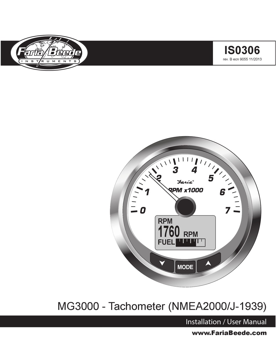
Faria Beede Mg3000 Installation User Manual Pdf Download Manualslib

Gm Tachometer Wiring Diagram Images Nomor Siapa

Faria Euro Black 4 Tachometer W Systemcheck Indicator 7 000 Rpm Gas Johnson Evinrude Outboard Tachometer Outboard Gas
Fiberglassics Tach Wiring Nj Triton Fiberglassics Forums

Vdo Performance Instruments

Aurora Instruments Custom Gauges Face Kits Installation Aurora Instruments Custom Gauges Amp Face Kits Installation Pdf Pdf4pro
Faria Gauge Replacement Planetnautique Forums

How To Install Wire Up A Tach Tachometer The Right Way Gm For Beginners Diy Youtube

Faria Boat Tach Wiring Basic Electronics Wiring Diagram Pdf
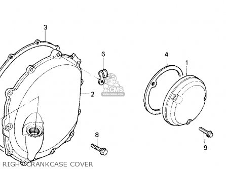
Gauge Oil Level For Cbr1000f Hurricane1000 1988 J Switzerland Order At Cmsnl
Faria Instruments Suzuki Automobile Parts User Manual Manualzz

Owner Acirc Euro Trade S Manual Faria Beede Instruments Inc Faria Digital Speedometer With Analog Appearance Pdf Document

Vdo Tachometer 0 515 012 037 Manualzz
Nautiqueparts Com

Manuals For Faria Marine Instruments Marine Diesel Basics
Rally Pac Schematic Ford Mustang Forum

Dash Tach Wiring Help Comet Performance

Boat Tachometer Wiring Diagram Wiring Diagram Images
Repair For Dead Gauges On 2003 2006 Nautiques Caused By Bad Faria Gateway Planetnautique Forums
0 Response to "41 faria tachometer wiring diagram"
Post a Comment