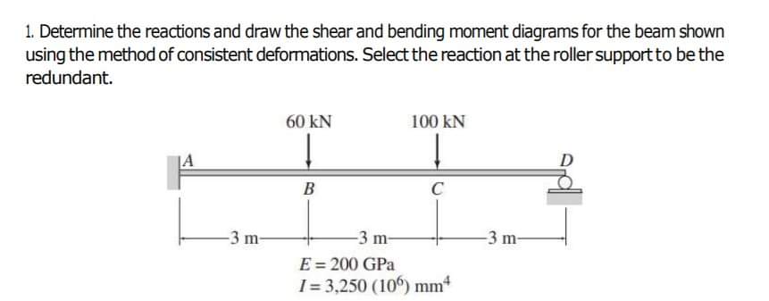
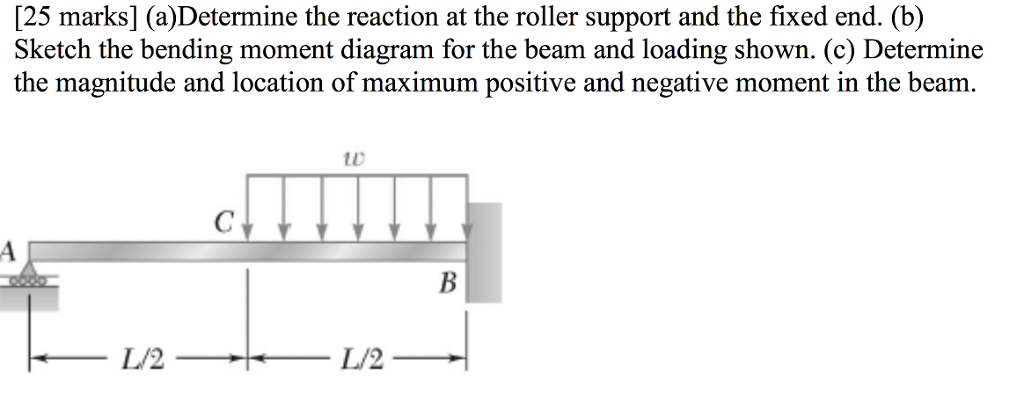
41 determine the reaction at the roller support and draw the bending moment diagram
a) Calculate the shear force and bending moment for the beam subjected to a concentrated load as shown in the figure, and draw the shear force diagram (SFD) and bending moment diagram (BMD). b) If P = 20 kN and L = 6 m, draw the SFD and BMD for the beam. P kN L/2 L/2 A B Using the Moment Area Theorems. The moment area theorems rely on the bending moment diagram, so at first this should have been determined. Secondly, drawing a rough sketch of the expected deflected shape of the structure proves quite helpful, because the methodology uses the the geometric relationships between slopes and deflections, that are specific to the examined structure.
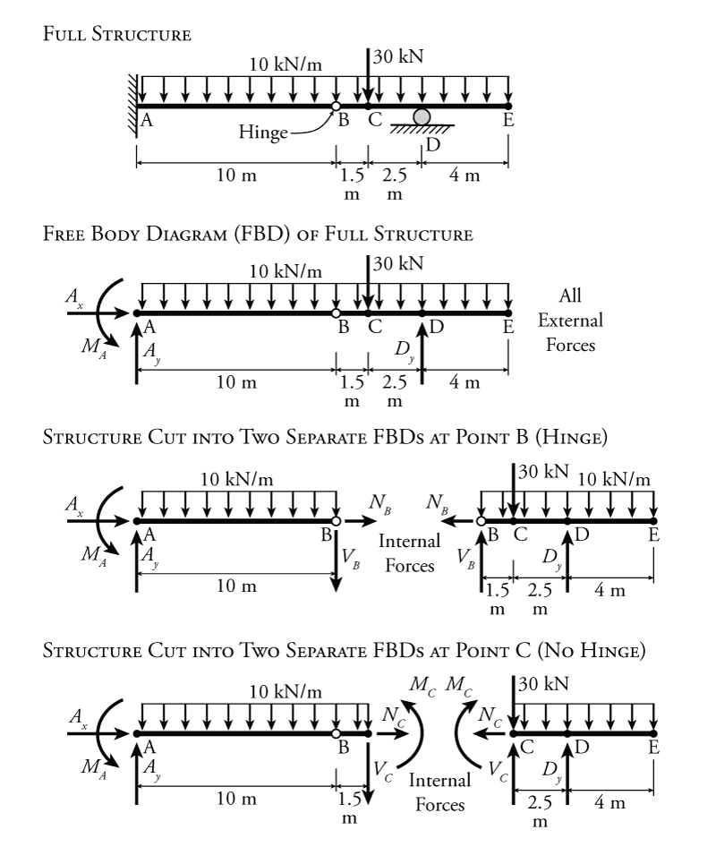
(1) Derive the shear and bending moment equations. And (2) draw the shear force and bending moment diagrams. Neglect the weight of the beam. The support reactions A and C have been computed, and their values are shown in Fig. (a). Solution Part 1 Due to the presence of the couple C 0, We must analyze segments AB and BC separately.

Determine the reaction at the roller support and draw the bending moment diagram
PDF_C8_b (Shear Forces and Bending Moments in Beams) Q6: A simply supported beam with a triangularly distributed downward load is shown in Fig. Calculate reaction; draw shear force diagram; find location of V=0; calculate maximum moment, and draw the moment diagram. 6k/ft 9 ft RA = (27k)(9-6)/9= 9k A B F = (0.5x6x9) = 27k x = (2/3)(9) = 6 ft Dr. M.E. Haque, P.E. Beam Reactions, Shear and Moment (Page 7 of 12) w L Sym. 2 / 8 - w x2 /2 w x2 /2 P 1 L / 4 P 2 x w L / 2 + P 1 / 2 MOMENT DIAGRAMS Fig. 1 Fig. 2 Fig. 3 Algebraic summation of coordinates of these three moment diagrams will produce the final moment diagram. simple support will develop a reaction normal to the beam, but will not produce a moment at the reaction. If either, or both ends of a beam projects beyond the supports, it is called ... equilibrium to determine the reactions. Figure 3.1 Example of a bent beam (loaded at its third points) ... obtain the bending moment, ...
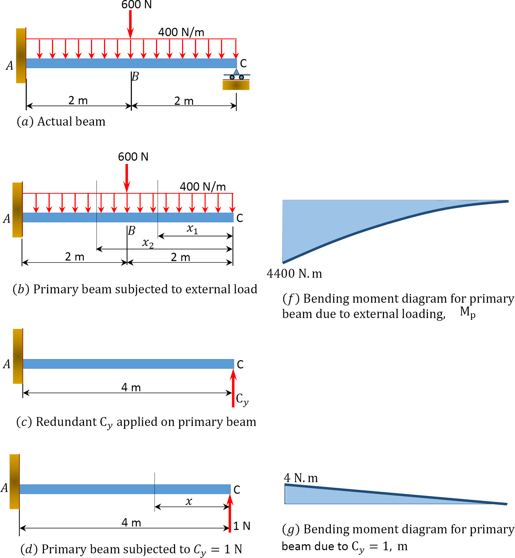
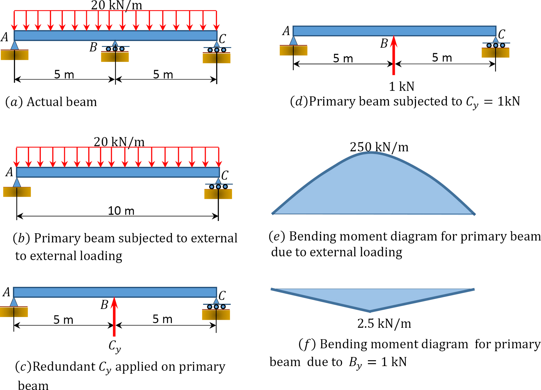
Determine the reaction at the roller support and draw the bending moment diagram. Determine the reaction at the roller support and draw the bending moment diagram for the beam and loading shown. SOLUTION Remove support at A and treat R A as redundant. Draw bending moment diagram by parts. A 1 = 1 2 4 5. R EI A F H I K (4.5) = 10125. This website is great; the best one that I have found so far to draw shear force and bending moment diagrams. Three ways in which it could be improved: 1) Allow a distributed load to be inputted as an equation i.e. more complex distributed load. 2) Calculate the shear force and bending moment diagrams for frames as well. Method to determine support reaction. For the estimation of loads and deformations, support reactions should be determined initially. There are a few basic steps to be followed to determine support reactions. Free-body diagram . The very first step in determining unknown reactions is to first draw a free-body diagram. Shear and bending moment diagrams depict the variation of these quantities along the length of the member. Proceeding from one end of the member to the other, sections are passed. After each successive change in loading along the length of the member, a FBD (Free Body Diagram) is drawn to determine the equations express-ing the shear and ...
Bending Moments Diagram: At the ends of a simply supported beam the bending moments are zero. At the wall of a cantilever beam, the bending moment equals the moment reaction. At the free end, the bending moment is zero. At the location where the shear force crosses the zero axis the corresponding bending moment has a maximum value. Determine The Reactions And Draw Shear Bending Moment Diagrams For Beams Shown In Figs P13 1 4 Using Method Of Consistent Deformations Select Reaction At Roller Support To. Solved S 1 Yze The Beam In Fig 5 21 By Method O Chegg. Solved Exle On Indeterminate Structure By Method Of Consistent Deformation. Chapter 13 Solutions Structural Ysis 6th ... determine the force in link DE and the components of the force exerted at C on member BCD. SOLUTION: • Create a free-body diagram for the complete frame and solve for the support reactions. • Define a free-body diagram for member BCD. The force exerted by the link DE has a known line of action but unknown magnitude. It is determined by summing .7—1. Determine the internal normal force and shear force, and the bending moment in the beam at points C and D. Assume the support at B is a roller. Point C is located just to the right of the 8-kip load. Suppon Reactions : FBD (a) B, = 1.00 kip A, +1.00-8-0 A, —700kip Internal Forces : Applying quadons Of to A C (FBD (b)), we have = O; 8 kip
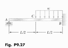
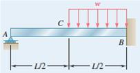
Setting the bending diagrams of beam. Calculate the reactions at the supports of a beam. Bending moment diagram (BMD) Shear force diagram (SFD) Axial force diagram. Invert Diagram of Moment (BMD) - Moment is positive, when tension at the bottom of the beam. Draw the SFD and BMD for the beam Solution: Draw FBD of the entire beam and calculate support reactions using equilibrium equations Reactions at supports: 2 wL R A R B w Develop the relations between loading, shear force, and bending moment and plot the SFD and BMD ME101 - Division III Kaustubh Dasgupta 10 Example 2. A simply supported beam is loaded as shown in the diagram. Calculate the support reactions and draw the Bending Moment diagram, Shear Force Diagram, Axial Force Diagram. Determine the maximum bending moment. Determine the reaction at the roller support and draw | Chegg.com. Engineering. Civil Engineering. Civil Engineering questions and answers. Determine the reaction at the roller support and draw the bending moment diagram for the beam and loading shown. to C A B 니 L/2 -L/2- > Use energy methods.
For He Beam Structures Shown Below Draw The Normal Force Nfd Shear Force Sfd And The Bending Moment Bmd Diagrams Study Com
4.0 Building Shear and Moment Diagrams. In the last section we worked out how to evaluate the internal shear force and bending moment at a discrete location using imaginary cuts. But to draw a shear force and bending moment diagram, we need to know how these values change across the structure.

Determine The Reactions At The Roller Support B Of The Beam Shown In Fig 12 44 A Then Draw The Shear And Moment Diagrams Ei Is Constant Holooly Com
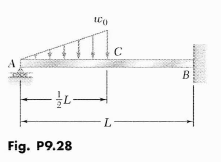
9.19 through 9.22 For the beam and loading shown, determine the reaction at the roller support. s 31-2 x +2L3) (L Problem 9.21 ) WOL 20. ... 9.33 and 9„34 Determine the reaction at A and draw the bending moment diagram for the beam and loading shown VI -I-wl-¾ O] Q +10 -B -h 43 o
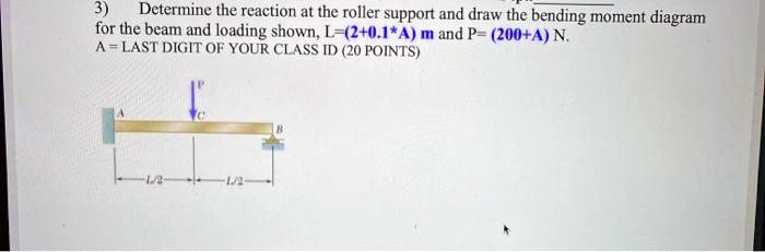
Solved Determine The Reaction At The Roller Support And Draw The Bending Moment Diagram For The Beam And Loading Shown L 2 0 1 4 M And P 200 4 N A Last Digit Of Your Class Id 20
- The force that results in bending is known as bending moment - Draw the shear force and bending moment diagrams ... roller at B. Calculate the reactions at both supports due to the loading. 20 kN 40 kN 2 m 3 m 4 m ... bending moment diagram (BMD). b) If P = 20 kN and L = 6 m, draw the SFD and BMD for the beam. P kN
Civilittee Hu Com
that "peaks" in the bending moment diagram frequently occur at concentrated loads or reactions, and these are not given by ; although they may in fact represent the greatest bending moment on the beam. Consequently, it is not always sufficient to investigate the points of zero shearing force when determining the maximum bending moment.

Use Castiglianos Theorem 10 Determine The Reaction At The Roller Support And Draw The Shear And Homeworklib
maximum shears and maximum bending moment develop. Determine these maximum values. 5. Derive the influence diagram for reactions and bending moment at any section of a simply supported beam. Using the ILD, determine the support reactions and find bending moment at 2m, 4m and 6m for a simply supported beam of span 8m subjected to three

Use Integration Method Determine The Reaction At The Roller Support And Draw The Bending Moment Diagram Homeworklib
Determine the reaction at the roller support, and draw the bending moment diagram for the beam and loading shown. Step-by-step solution. 84% (25 ratings) for this solution. Step 1 of 5. Free body diagram of the given beam is. Chapter 9, Problem 26P is solved.
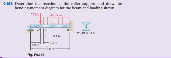
Solved 9 168 Determine The Reaction At The Roller Support Chegg Com
• Draw the influence lines for the shear -force and bending -moment at point C for the following beam. • Find the maximum bending moment at C due to a 400 lb load moving across the beam. Example
1 10 Force Method Of Analysis Of Indeterminate Structures Engineering Libretexts
Problem 6: Bending Moment Diagram Plot shear and bending-moment diagrams for a simply supported beam with a uniformly distributed load; see Figure. Figure Solution A section at a distance x from the left support is taken as shown in figure (b). The shear is found out by subtracting the load to the left of the section from the left upward reaction.
Solved Zux Analyze The Beam Shown On The Right 12k Using The Force Method The Structure A L D Is Subjected To Two Concentrated Loads B And A Small Course Hero
Determine the reaction at the roller support and draw the bending moment diagram for the beam and loading shown. Step-by-step solution: 94 % ( 17 ratings) for this solution. Chapter: CH1 CH2 CH3 CH4 CH5 CH6 CH7 CH8 CH9 CH10 CH11. CH9.

For The Beam Shown Below A Find The Support Reactions At A And C Note A Is Fixed B Is An Internal Hinge And C Is A Roller B Draw The Shear
Positive bending moment diagram drawn BELOW the beam; EXAMPLE 4. Calculate the shear force and bending moment for the beam subjected to a concentrated load as shown in the figure. Then, draw the shear force diagram (SFD) and bending moment diagram (BMD). If P = 20 kN and L = 6 m, draw the SFD and BMD for the beam. EXAMPLE 4 - Solution
3
This process is illustrated in Figure 6.7. Figure 6.7: Use of the Müller Breslau Principle for Vertical and Horizontal Reaction Influence Lines. In Figure 6.7, a full example structure is shown at the top. This example structure has two roller supports, one at point B and one at point D, and a fixed support at the right end at point F.
Ncet Co In
simple support will develop a reaction normal to the beam, but will not produce a moment at the reaction. If either, or both ends of a beam projects beyond the supports, it is called ... equilibrium to determine the reactions. Figure 3.1 Example of a bent beam (loaded at its third points) ... obtain the bending moment, ...
Solved 1 Through 12 21 Determine The Approximate Axial Forces Shears 1 Answer Transtutors
Dr. M.E. Haque, P.E. Beam Reactions, Shear and Moment (Page 7 of 12) w L Sym. 2 / 8 - w x2 /2 w x2 /2 P 1 L / 4 P 2 x w L / 2 + P 1 / 2 MOMENT DIAGRAMS Fig. 1 Fig. 2 Fig. 3 Algebraic summation of coordinates of these three moment diagrams will produce the final moment diagram.
Solved Determine The Reaction At The Roller Support And Draw The Chegg Com
PDF_C8_b (Shear Forces and Bending Moments in Beams) Q6: A simply supported beam with a triangularly distributed downward load is shown in Fig. Calculate reaction; draw shear force diagram; find location of V=0; calculate maximum moment, and draw the moment diagram. 6k/ft 9 ft RA = (27k)(9-6)/9= 9k A B F = (0.5x6x9) = 27k x = (2/3)(9) = 6 ft

Problem 11 Determine The Reaction At The Roller Support And The Deflection At Point C Fig Homeworklib
Shear Force And Bending Moment Diagram For Simple Supported Beam

Moment Diagrams Constructed By The Method Of Superposition Mo Civil Engineering
Engr Uky Edu
1 10 Force Method Of Analysis Of Indeterminate Structures Engineering Libretexts
Propped Beam Mathalino Reviewers Tagged With Propped Beam
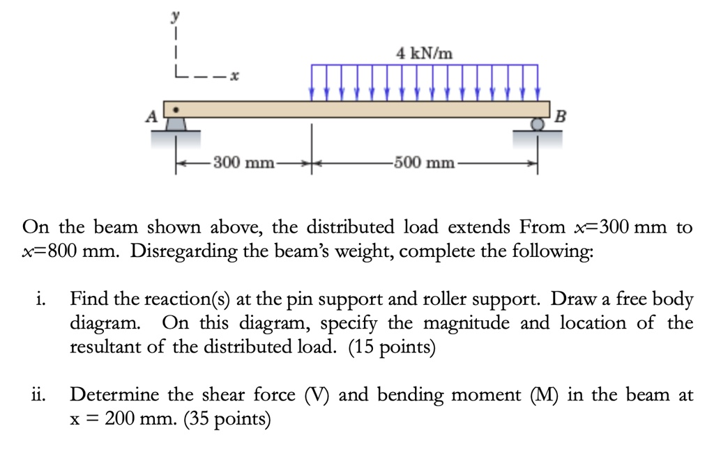
Solved 4 Knim Ct 300 Mm 500 Mm On The Beam Shown Above The Distributed Load Extends From X 3 300 Mm To X 800 Mm Disregarding The Beam S Weight Complete The Following Find

Plot The Shear And Moment Diagrams For The Beam Loaded With Both The Distributed Load And The Couple At X 1 8 5 2 8 3 11 3 What Is The Shear Force And The
Solved Determine The Reaction At The Roller Support And Draw The Chegg Com
Problems Bending Of Beams Informit
Solved Determine The Reaction At The Roller Support And Draw The Chegg Com
Reactions Of Propped Beam Mathalino Reviewers Tagged With Reactions Of Propped Beam
4 Shear Forces And Bending Moments
A 6 M Long Beam Ab Is Hinged At End A Roller Supported At End B Carries Udl Of 6kn M Over Ac 3 M And A Point Load Of 12kn Sarthaks Econnect
Answered 1 Determine The Reactions And Draw The Bartleby
1 6 External And Internal Forces Directions And Notation Learn About Structures
Solved Determine The Reaction At The Roller Support And Draw The Chegg Com

Roller Support An Overview Sciencedirect Topics
Solved A Determine The Reaction At The Roller Support And Chegg Com

Shear Force Bending Moment With Triangular Load On Beam Youtube
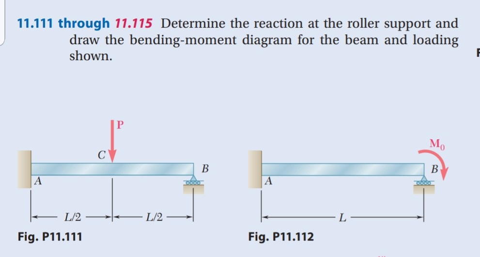
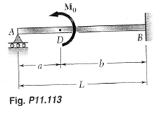
Solved 11 111 Through 11 115 Determine The Reaction At The Chegg Com
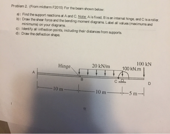
Solved For The Beam Shown Below A Find The Support Reactions At A And C 1 Answer Transtutors
1 10 Force Method Of Analysis Of Indeterminate Structures Engineering Libretexts
1

Determine The Reaction At The Roller Support And Draw The Shear And Bending Moment Diagrams For The Beam And Load Shown Study Com
Web Ncyu Edu Tw
Ncet Co In
0 Response to "41 determine the reaction at the roller support and draw the bending moment diagram"
Post a Comment