40 heat trace wiring diagram
Assortment of heat trace wiring diagram. A wiring diagram is a simplified traditional photographic depiction of an electrical circuit. It reveals the components of the circuit as simplified forms, and also the power and signal links in between the devices. Electric heat tracing systems are designed to make up for the heat lost from process system equipment through the thermal insulation. In some cases, the heat tracing system can be used for system heat-up at initial startup or after a power shutdown. The information in this design guide will allow the
INSTALLATION AND WIRING 2.1 INTRODUCTION This section includes information regarding the initial inspection, preparation for use, and storage instructions for the C910-485 Heat Trace controllers. 2.2 INITIAL INSPECTION Inspect the shipping container for damage. If the shipping container or cushioning

Heat trace wiring diagram
19 May 2021 — Check out the diagram below to see what a completed heat trace system ... You'll need a pair of wire cutters and an insulation resistance ... Heat Trace Wiring Diagram Gallery. heat trace wiring diagram - A Newbie s Overview of Circuit Diagrams An initial take a look at a circuit representation might be confusing, but if you could check out a subway map, you can review schematics. The function is the exact same: obtaining from factor A to direct B.… Installation And Maintenance Manual Ga 2129 Cm 1 Heat Trace Circuit Management System R11. Chromalox Thermostat Wiring Diagrams For Hvac Systems Installation Instructions. Intech 21 Inc Hccm 2100 Heater Cable Control And Monitoring System Installation Manual Addressing Procedure.
Heat trace wiring diagram. Use of the Manual. This manual covers the basics of installation and maintenance for nVent RAYCHEM Series Resistance. (SC) heat-tracing systems. DOWNLOAD. Wiring Diagram Sheets Detail: Name: heat trace wiring diagram – Heat Trace Wiring Diagram Unique Stunning Lennox Ac Wiring Diagram Ideas Electrical Circuit. File Type: JPG. Source: kmestc.com. Size: 128.18 KB. Dimension: 685 x 612. See also Honeywell Rm7840l1018 Wiring Diagram Sample. DOWNLOAD. HEAT TRACING PRODUCT - Training Manual. CHROMALOX.. TRAINING. Chapter 1: Heating Fundamentals. Before plunging headfirst into a myriad of heat trace ...76 pages Maintenance of electric heat tracing systems shall conform to all IEC requirements for the use of electrical equipment and with the requirements of the relevant heat tracing standard, usually either IEC 62395 Electrical resistance trace heating systems for industrial and commercial applications or IEC 60079-30 Explosive atmospheres - electrical
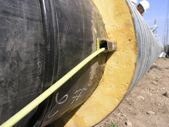
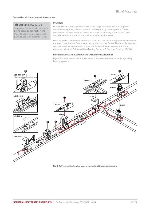
isometric system diagrams (if provided). • Lay out the trace heater on the pipe, at the 4 or 8 o’clock position (Illustration B), securing it tightly against the pipe with attachment tape. Wrap bands of tape around the trace heater and pipe at intervals of 12” (30 cm) or less, keeping the trace heater in close contact with the pipe. Specify nVent RAYCHEM for Buildings and Infrastructure. Specify nVent RAYCHEM for your projects to bring maximum winter protection and optimum safety for plumbing, HVAC, and fire suppression pipes, or roof, pathway, and ramp surfaces. Download our specifications from MasterSpec today. Visit MasterSpec. arrow-right. Refer to Pentair Thermal Management product literature and the TraceCalc software to select the proper heating cable for each thermal, chemical, electrical and ...36 pages These wiring diagrams are located at the back of the manual. The PLT-CMD is used to monitor bus continuity on a parallel type heating.24 pages
heat trace pipes, valves and flanges. Alternate Voltages RSCC 240 VAC self-regulatingheating cables can be operated at alternative voltages. The chart below compares heating cable power output with prod-uct rating. Power Adjustment Factor Part No. 208 Volts 277 Volts 2703-2 .75 1.28 2705-2 .86 1.16 Applications, Systems, Heat Tracing, Documents, Learning Centre, About URECON ... Wiring Diagram. NGUTC-2030 & NGUTC-2230. Wiring Diagram. NGUTC-VPAA. describe the installation of Thermon trace heating ... High-temperature limit switch activated • May require manual reset to re-enable trace heating circuit.16 pages Installation And Maintenance Manual Ga 2129 Cm 1 Heat Trace Circuit Management System R11. Chromalox Thermostat Wiring Diagrams For Hvac Systems Installation Instructions. Intech 21 Inc Hccm 2100 Heater Cable Control And Monitoring System Installation Manual Addressing Procedure.
Heat Trace Wiring Diagram Gallery | Wiring Collection
Heat Trace Wiring Diagram Gallery. heat trace wiring diagram - A Newbie s Overview of Circuit Diagrams An initial take a look at a circuit representation might be confusing, but if you could check out a subway map, you can review schematics. The function is the exact same: obtaining from factor A to direct B.…

How to Re-Wire Your Car (Replacing the Wiring Harness): Part 2
19 May 2021 — Check out the diagram below to see what a completed heat trace system ... You'll need a pair of wire cutters and an insulation resistance ...

AMP and Head Unit Wiring Diagram - Land Rover Forums ...

Скачать Trane Heat Pump Wiring And Air Handler Diagram ...

International Comfort Products Wiring Diagram

Tempstar Heat Pump Wiring Diagram - Wiring Forums

Famous Lennox Thermostat Wiring Diagram Image Collection ...
Descargar Elegant Heat Trace Wiring Diagram Di 2020 ...

Télécharger Heat Pump First Stage Heat Wiring Diagram ...

Schluter Ditra Heat Thermostat Wiring Diagram

Heat Pump With Aux Heat Wiring Diagram - Database - Wiring ...
Trane Air Conditioning Wiring Diagrams - Ekocraft Apple Leaf
![[DIAGRAM] Installing New Head Unit Wiring Diagram FULL ...](https://blogger.googleusercontent.com/img/b/R29vZ2xl/AVvXsEixz4ZFz4vB47QaoBcDDlRW4DsvXWW8q9G9lmylV4rYNSGvKF19TG-kDS0Unw8JViHxV4jNNdKT98p5Dyc1X7acI7r1QN7z6sLaNdWQ7rn8ZCLJ7aCKk_d2za9PDmb4EaKQLyQ4XBMN8qVY/s1600/%25E7%2594%25B5%25E6%25BA%2590%25E7%25BA%25BF%25E3%2580%2582%25E9%259F%25B3%25E9%25A2%2591%25E7%25BA%25BF%25E9%2593%25BE%25E6%258E%25A5%25E5%259B%25BE.png)
[DIAGRAM] Installing New Head Unit Wiring Diagram FULL ...

Trane Heat Pump Wiring Diagram | Heat pump compressor Fan ...

The Quintessential Guide: Troubleshooting Electrical Heat ...
Raychem Heat Trace Wiring Diagram
/1943LED(0601943739)-bosch-PB.png)
Heat Gun Schematic Diagram - FLY-UP-UP-HERE-WE-GO
Trane Air Conditioning Wiring Diagrams - Ekocraft Apple Leaf
![[DIAGRAM] Wiring Diagram For Heat Pump System pdf Download ...](https://pascol.biz/wiring-diagram-for-heat-pump-system.jpg)
[DIAGRAM] Wiring Diagram For Heat Pump System pdf Download ...

Tracing Panel Wiring Diagram Of An Alternator

Goodman 10kw Heat Strip Wiring Diagram
Wiring Diagram Rv Dometic 15000 Heat Pump - Database ...
Heat Tracing
![[DIAGRAM] Minn Kota Wiring Diagram Photo Album Wire Images ...](https://headcontrolsystem.com/wp-content/uploads/2018/08/minn-kota-wiring-diagram-manual-minn-kota-wiring-diagram-12-volt-solidfonts-5t.jpg)
[DIAGRAM] Minn Kota Wiring Diagram Photo Album Wire Images ...

Get Heat Trace Wiring Diagram Sample
Self Regulating Heat Trace Guide

Harmony

Honeywell Heat Pump Thermostat Wiring Diagram - U Wiring

Lennox Nest Wiring Diagram | Nest Wiring Diagram
Heat Trace Wiring Diagram

Is Your Process Right for Heat Tracing? | 2007-01-01 ...

Nest T3007Es Wiring Diagram With Heat Pump | Nest Wiring ...
Thermostat Wiring Diagram For Goodman Heat Pump - Database ...

S Plan Central Heating System Lively Heat Trace Wiring ...

Arcoaire Thermostat Wiring Diagram Fantastic Pictures Of ...
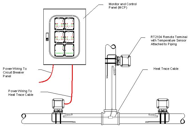
Intech 21, Inc. Design Guide 1
Wireing Multple Basebords On One thermostat Best Of ...

Carrier Heat Pump Wiring Diagram thermostat Download

Heat Tracing Cable and Electrical Panels Manufacturer ...

Heat Trace Wiring Diagram
0 Response to "40 heat trace wiring diagram"
Post a Comment