39 log splitter hydraulic circuit diagram
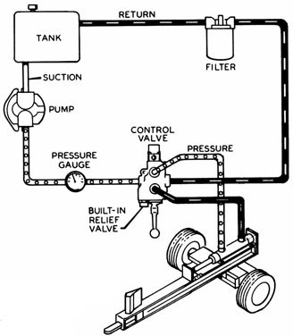
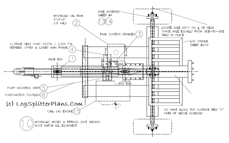
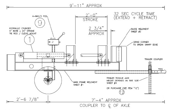
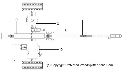
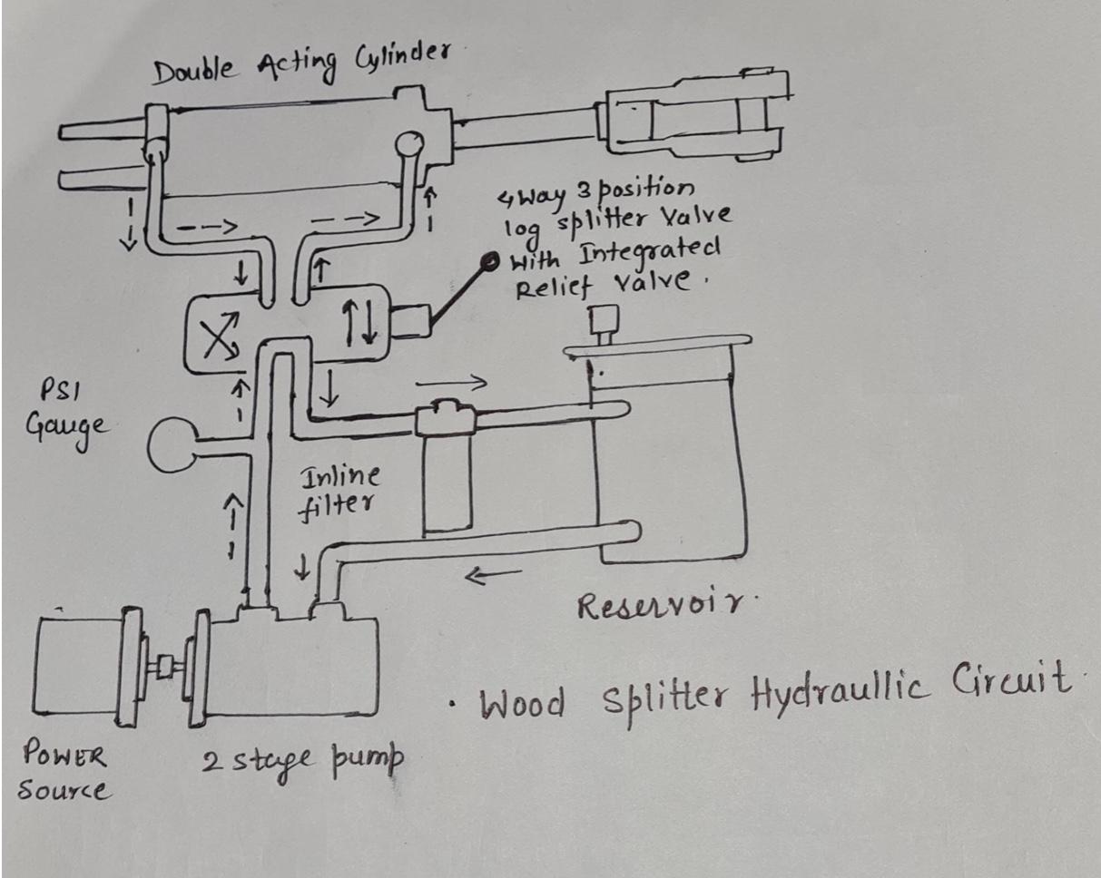
Sep 27 2016 image result for log splitter hydraulic circuit diagram. A log splitter is a machine with several components that make short order work of splitting firewood quickly and with much less effort. A hydraulic circuit 21 30 38 42 44 46 46 48 having a predetermined maximum design pressure rating. If you have a wood burning fireplace or ... The Log Splitter Hydraulic Circuit. Most log splitters use a hydraulic cylinder ( like these) to push a cut piece of log into a sharpened wedge, which splits it. The cylinder is driven by hydraulic oil, under pressure, produced by a hydraulic pump. An engine, or electric motor, drives the pump shaft, and supplies the power for the system.
Page 5 • NEVER use this log splitter for any other purposes than splitting wood.It is designed for this use only.Any other use can cause serious injury or death. • BEFORE operating this log splitter, make sure that you wear safety gear such as goggles or safety glasses, steel toed shoes and tight fitting gloves (without loose cuffs or draw strings).
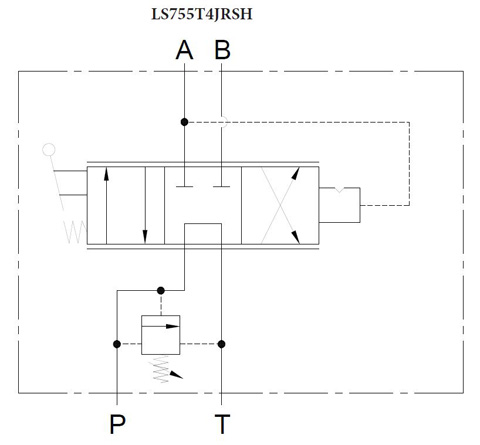
Log splitter hydraulic circuit diagram
Freeing a Jammed Log 9 Replacing Hydraulic Oil 10 Sharpening the Wedge 10 Troubleshooting 11 Wiring Diagram 11 Plumbing Diagram 11 ... Your log splitter will do a better and safer job at its design ... Check that the electric circuit is grounded, adequately protected, and that it corresponds with the power, voltage, and frequency of ... 1 Find the diagram. Find the diagram of the detent valve set up. There will be input valves for the pressurized and un-pressurized hose connections, and the diagram will show you which ones go on which side of the detent valve and in what order. If the hydraulic hoses are hooked up incorrectly, then the valve won't be able to function properly. INSTRUCTIONS FOR REPLACEMENT OF SEALS IN THE LOG SPLITTER KICKOUT VALVE ASSEMBLY **NOTE** these instructions apply to replacing the seals in the ENERGY DSKCVA-200 series log splitter valves. 1. It is possible to replace the seals without removing the valve from the hydraulic system. Be certain the valve is clean and dry. If you prefer, dismount
Log splitter hydraulic circuit diagram. Description : Speeco S390406Sc Log Splitter Valve - Omni Mfg Llc with regard to Huskee Log Splitter Parts Diagram, image size 500 X 380 px, and to view image details please click the image. Here is a picture gallery about huskee log splitter parts diagram complete with the description of the image, please find the image you need. The log splitter changes all of that! A log splitter is a machine with several components that make short order work of splitting firewood quickly and with much less effort. Before you shell a whole bunch of cash to buy or build a log splitter, lets review the wood splitter hydraulic components that make up this wood chopping machine. Hydraulic Oil Reservoir Log Splitter Valve Auto Cycle Valve . Open Center hydraulic Valve: There are two basic valve systems used on log splitters: They come with different options . 1-Log splitter valve - You have to hold the valve lever on the splitting stroke & on the return stroke, there is a detent to The diagram shows the pusher assembly for the J-Model SuperSplit unit. Each of the two side guides on the J-Model require one (and only one) bearing (part # 063).If you have a J-Model, you may order parts according to the part numbers shown in the diagram.
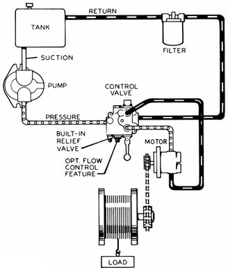
The diagram shows a winch powered by a hydraulic motor. The directional control valve with built-in relief features optional flow control to control the speed of the winch . The hydraulic pump and motor must be matched to the torque requirements of the winch. Logsplitter. to ensure the log splitter works under pressure no more than is listed in the specifications. The setting was made by a qualified mechanic with professional instruments. Unauthorised resetting will reduce the performance of the hydraulic pump or RESULT IN SERIOUS INJURY AS WELL AS DAMAGE TO THE MACHINE. WIRING DIAGRAM HYDRAULIC DIAGRAM g) Always check the oil level of the hydraulic reservoir before operation. Operating the log splitter without an adequate oil supply will cause severe damage to the pump. h) Keep handles free of oil, grease and resin. i) Before starting work, hydraulic pipes and hoses shall be inspected and the stopping devices should be tested. Circuit idea: two-speed log splitter. Feb. 18, 2014. If you have a wood-burning fireplace or stove, this long, cold winter may have depleted your stockpile of firewood. And if you're like most fluid-power aficionados, you've dreamt of applying your knowledge to build your own hydraulic log splitter.
Hydraulic Two-Stage / Log Splitter Pumps Model Specs 815.397.4701 // SALES@MTEHYDRAULICS.COM We're experts at hydraulic pumps, motors and power units, and pride ourselves in our ability to address your needs - whether a special prototype or high production unit. ONLY operate the log splitter from the operator zone as shown in the diagram. Operating the log splitter in another location can result in serious injury or death. • ALWAYS chock the wheels to prevent movement of the log splitter while in operation. • KNOW how to stop the log splitter and disengage the controls before operating it. The USA's most popular log splitter valve. Specified by Spring centered in one direction, and pressure released detent in the other direction. Automatically. The detent valve in a log splitter is the central assembly where the the diagram will show you which ones go on which side of the detent valve. Fig. 2 is a side schematic diagram of the log splitter shown in Fig. 1 Fig. 3 is a cross sectional side elevational view of the hydraulic control valve, cylinder and ram of the present invention. Fig. 4 is an enlarged fragmentary cross sectional View of the control valve of Fig. 3 in which the valve is in a neutral position.
Fig. 2 is a side schematic diagram of the log splitter shown in Fig. 1 Fig. 3 is a cross sectional side elevational view of the hydraulic control valve, cylinder and ram of the present invention. Fig. 4 is an enlarged fragmentary cross sectional View of the control valve of Fig. 3 in which the valve is in a neutral position.
Parts Lists, Schematic Diagrams And Warranty Parts List - DR 5-TON ELECTRIC LOG SPLITTER. NOTE: Part numbers listed are available through DR Power Equipment. Ref# Part# Description 2. 33483 Ram Cap & Shaft 3. 33484 Upper Nylon Cushion 4. 33485 Lower Nylon Cushion 6. 33486 Flat Washer, M8*1 7. 33487 Spring Washer, M8*2.3 17. 33488 Nut , M14 18. 33489 Lock Nut , M14

Hbs Integrated Block With Spool Valve Regenerative System For Wood Splitter 1 2 G Standard Ovc1 20bar Standard Valv 4 240bar Standard Valv5 180bar
Gas Log Splitter Operator's Manual ... Assembly 12 Parts Diagram 25 ... Pay attention to all cautions and warnings. This unit is a gasoline engine driven hydraulic log splitter. It is designed to split wood logs for use as firewood for a stove or fireplace. This log splitter will only split logs lengthwise with the grain.

Numerical And Experimental Investigation On Rock Breaking Performance With Hydraulic Splitter Sciencedirect
GENERAL SAFETY ALWAYS keep the operator's manual nearby for reference.Reread the manual periodically. ALWAYS keep all bystanders and pets a minimum of 10 feet away from your work area when operating this log splitter. Only the operator is to be near the log splitter during use. NEVER allow adults lacking proper instructions and understanding to operate this log splitter.
The hydraulic system of your log splitter requires careful inspection along with the mechanical parts. Be sure to replace frayed, kinked, cracked or otherwise damaged hydraulic hose and components. ... STEP 2: Attach the tongue (3) to the tank/axle (2) as shown in the diagram using the two 1/2 in. NC x 4-1/2 in. hex cap screws (75), 1/2 in.
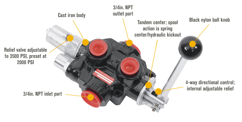
LOGSPLITTER VALVES WITH HYDRAULIC KICK-OUT! The log splitter valve is a four-way hydraulic directional control valve designed to operate a two-way hy-draulic circuit from a single hydraulic source in an open center system. Pull handle out to extend cylinder. Handle is spring loaded, and will return to neutral when released.
An engine, normally a small four-stroke gasoline engine, provides the power for the system.The engine is attached to a hydraulic oil pump. The hydraulic oil pump creates a stream of high-pressure oil, which runs to a valve.; The valve lets the operator actuate the hydraulic cylinder to split a log.; There is also a tank to hold the hydraulic oil that feeds the pump and usually a filter to keep ...
Oct 13, 2009. #1. I need a hydraulics diagram for building my own wood splitter, it will have two cylinders, one for splitting and one for a lifting tray to lift bigger pieces onto the splitter. the hydraulic pump I got has three ports one large port that comes from the oil reservoir [ this I know ] and the two other smaller ports are located ...
Hydraulic hoses are hooked up incorrectly. Find the diagram of the detent valve set up. There will be input valves for the pressurized and un-pressurized hose connections, and the diagram will show you which ones go on which side of the detent valve and in what order. Check for leaks. If the hoses aren't connected completely
A hydraulic pump produces liquid movement or the flow necessary to develop pressure, a function of resistance to fluid flow in the system. non-positive-displacement. Most pumps used in hydraulic systems are positive-displacement. In a positive-displacement pump, slippage is negligible compared to the pump's volumetric output flow.
Directional control valve - Log splitter Model P81 ... 1 0 2 Hydraulic scheme for P81 A2 S10 2/7 Sep 2013. Port type (S - UN-UNF, G - BSP, N-NPTF) Spool detent - detent with hydraulic release (70 to 140 bar) Spool type (A) Directional control valve (80 l/min) Order Code: P81 A 2 G 12
INSTRUCTIONS FOR REPLACEMENT OF SEALS IN THE LOG SPLITTER KICKOUT VALVE ASSEMBLY **NOTE** these instructions apply to replacing the seals in the ENERGY DSKCVA-200 series log splitter valves. 1. It is possible to replace the seals without removing the valve from the hydraulic system. Be certain the valve is clean and dry. If you prefer, dismount
1 Find the diagram. Find the diagram of the detent valve set up. There will be input valves for the pressurized and un-pressurized hose connections, and the diagram will show you which ones go on which side of the detent valve and in what order. If the hydraulic hoses are hooked up incorrectly, then the valve won't be able to function properly.
Freeing a Jammed Log 9 Replacing Hydraulic Oil 10 Sharpening the Wedge 10 Troubleshooting 11 Wiring Diagram 11 Plumbing Diagram 11 ... Your log splitter will do a better and safer job at its design ... Check that the electric circuit is grounded, adequately protected, and that it corresponds with the power, voltage, and frequency of ...

Buy Ruggedmade 30 Gpm Hydraulic Directional Control Valve Log Splitter Auto Return Detent Kick Off Control Valve Adjustable Relief Lever Handle 3500 Psi 3 4 Npt Work Ports Online In Indonesia B07fdhnjjd














0 Response to "39 log splitter hydraulic circuit diagram"
Post a Comment