38 using the isothermal transformation diagram
Alloy steel is steel that is alloyed with a variety of elements in total amounts between 1.0% and 50% by weight to improve its mechanical properties.Alloy steels are broken down into two groups: low alloy steels and high alloy steels. The difference between the two is disputed. Smith and Hashemi define the difference at 4.0%, while Degarmo, et al., define it at 8.0%. For an isothermal process PV = constant, dU = dQ - dW = 0. dQ = dW = PdV. Details of the calculation: 1 2 PdV = (nR) ∫ 1 2 (1/V)dV = nRln(V 2 /V 1). Problem: Calculate the entropy change of 1 mole of an ideal gas that undergoes an isothermal transformation from an initial state of pressure 1.5 atm and a volume of 500 cm 3 to a final state of ...
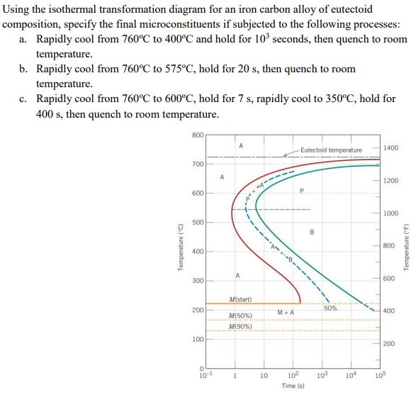
10.18 Using the isothermal transformation diagram for an iron–carbon alloy of eutectoid composition. (Figure 10.22), specify the nature of the final ...12 pages

Using the isothermal transformation diagram
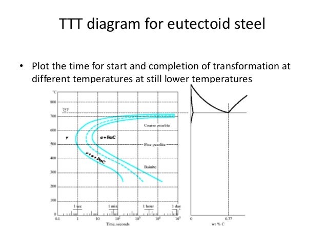
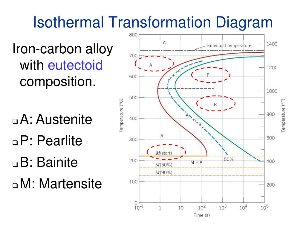
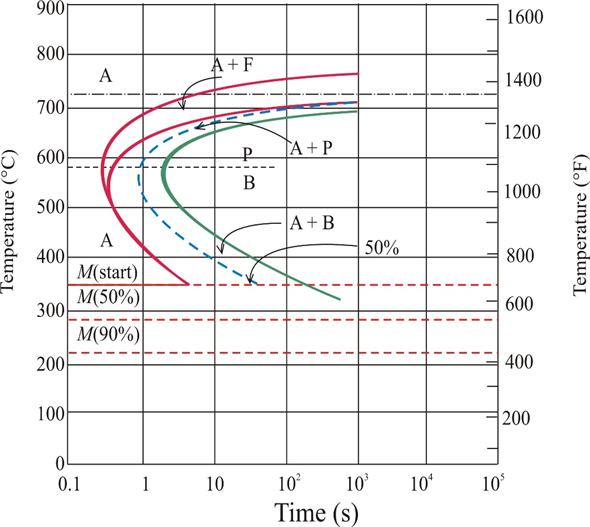
Time-Temperature-Transformation (TTT) diagram or S-curve refers to only one steel of a particular composition at a time, which applies to all carbon steels.This diagram is also called as C-curve isothermal (decomposition of austenite) diagram and Bain’s curve.The effect of time-temperature on the microstructure changes of steel can be shown by the TTT diagram. Using the isothermal transformation diagram for an iron-carbon alloy of eutectoid composition (see Figure 10.22 below), specify the nature of the final ... Isothermal transformation (IT) diagram or the C-curve is associated with mechanical properties, microconstituents/microstructures, and heat treatments in carbon ...
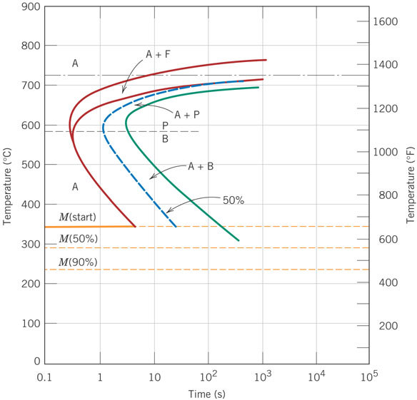
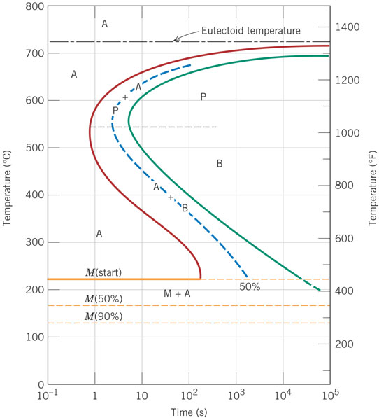
Using the isothermal transformation diagram. Sample records for isothermal transformation diagrams ... Shape of CCT diagram developed with use of isochronal cooling is different from conventional one. If we talk according to the iron-carbon equilibrium diagram the cementite will be converted to the spherical form. Isothermal Annealing. The isothermal process is done for the low carbon steels and alloy for improvement of their machinability. 10.18 Using the isothermal transformation diagram for an iron–carbon alloy of eutectoid composition (Figure 10.22), specify the nature of the final microstructure (in terms of microconstituents present and approximate percentages of each) of a small specimen that has been subjected to the following time–temperature treatments. In Local softening deformation and phase transformation induced by electric current in electrically-assisted micro-compression of Ti–6Al–4V alloy. ... the Joule heat induced deformation is not the same as the isothermal deformation. ... Schematic diagram of α→β→αʹ phase …
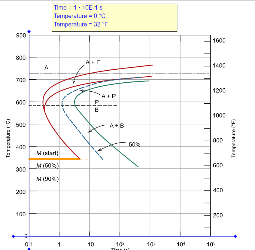
In thermodynamics, an isothermal process is a type of thermodynamic process in which the temperature of the system remains constant: ΔT = 0. This typically occurs when a system is in contact with an outside thermal reservoir , and the change in the system will occur slowly enough to allow the system to continue to adjust to the temperature of the reservoir through heat exchange (see quasi ... Isothermal transformation diagrams (also known as time-temperature-transformation (TTT) diagrams) are plots of temperature versus time (usually on a ... This is the second of three Coursera courses that mirror the Introduction to Materials Science class that is taken by most engineering undergrads at Georgia ... The work done in the cycle is equal to the area enclosed on a p V diagram. Therefore dw= ( v l)de s (3) Also, q h = l v, therefore, l v T = ( v l)de s dT (4) Which can be re-written as de s dT = l v T( v l) (5) Which is the Clausius-Clapeyron Equation 1a. Proof of Clausius-Clapeyron using Gibbs Function or Gibbs Free Energy For any two phases ...
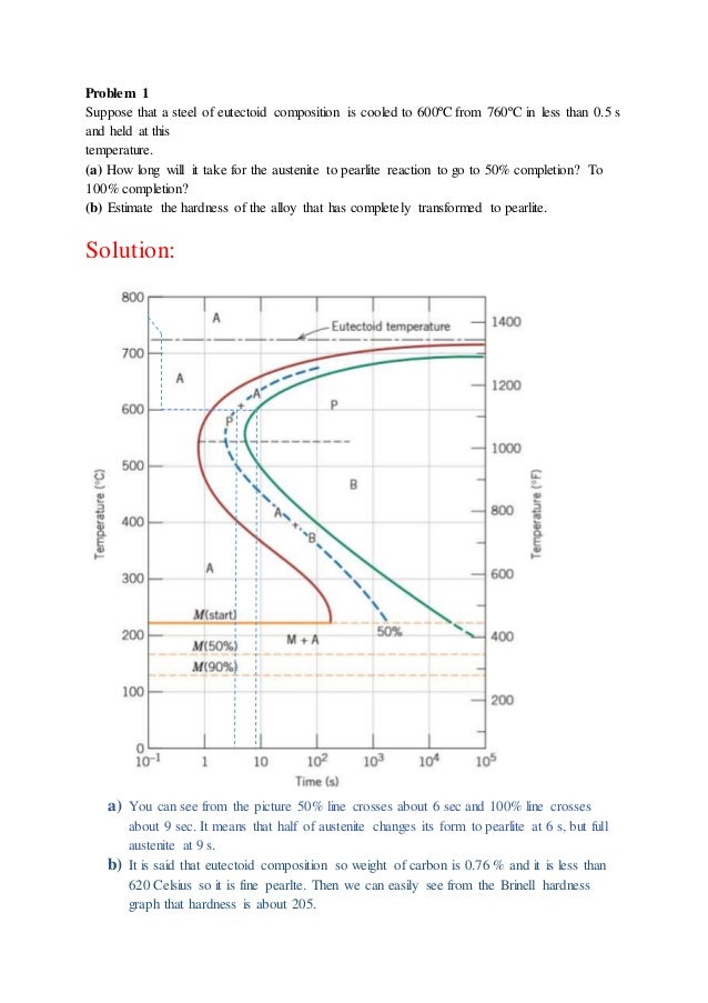
The Schmidt theory is one of the isothermal calculation methods for Stirling engines. It is the most simple method and very useful during Stirling engine development. This theory is based on the isothermal expansion and compression of an ideal gas. 2. ASSUMPTION OF SCHMIDT THEORY The performance of the engine can be calculated using a P-V diagram. This behavior is quantified in Figure 14.14. 140 Figure 14.14 is called an isothermal transformation diagram, and it represents the behavior of a eutectoid steel, or a steel with about 0.80% carbon. As an example, suppose that the steel is very rapidly cooled from 800 to 600 ... FREE Answer to Using the isothermal transformation diagram for an alloy steel (type 4340) specify the nature of the final microstruct...1 answer · 0 votes: but e es:duol Stressa preseal *o b) AAr ブ" 5% 10 . เจ. 5 Sinde he inside whan expoged to cons ;ση madium 10.18 Using the isothermal transformation diagram for an iron–carbon alloy of eutectoid composition. (Figure 10.22), specify the nature of the final ...27 pages
Isothermal transformation (IT) diagram or the C-curve is associated with mechanical properties, microconstituents/microstructures, and heat treatments in carbon ...

Using The Isothermal Transformation Diagram For An Iron Carbon Alloy Of Eutectoid Composition Figure 11 23 Specify The Nature Of The Final Microstructure In Terms Of Microconstituents Present And Study Com
Using the isothermal transformation diagram for an iron-carbon alloy of eutectoid composition (see Figure 10.22 below), specify the nature of the final ...

Atlas Of Isothermal Transformation And Cooling Transformation Diagrams American Society For Metals 9780412653407 Amazon Com Books
Time-Temperature-Transformation (TTT) diagram or S-curve refers to only one steel of a particular composition at a time, which applies to all carbon steels.This diagram is also called as C-curve isothermal (decomposition of austenite) diagram and Bain’s curve.The effect of time-temperature on the microstructure changes of steel can be shown by the TTT diagram.
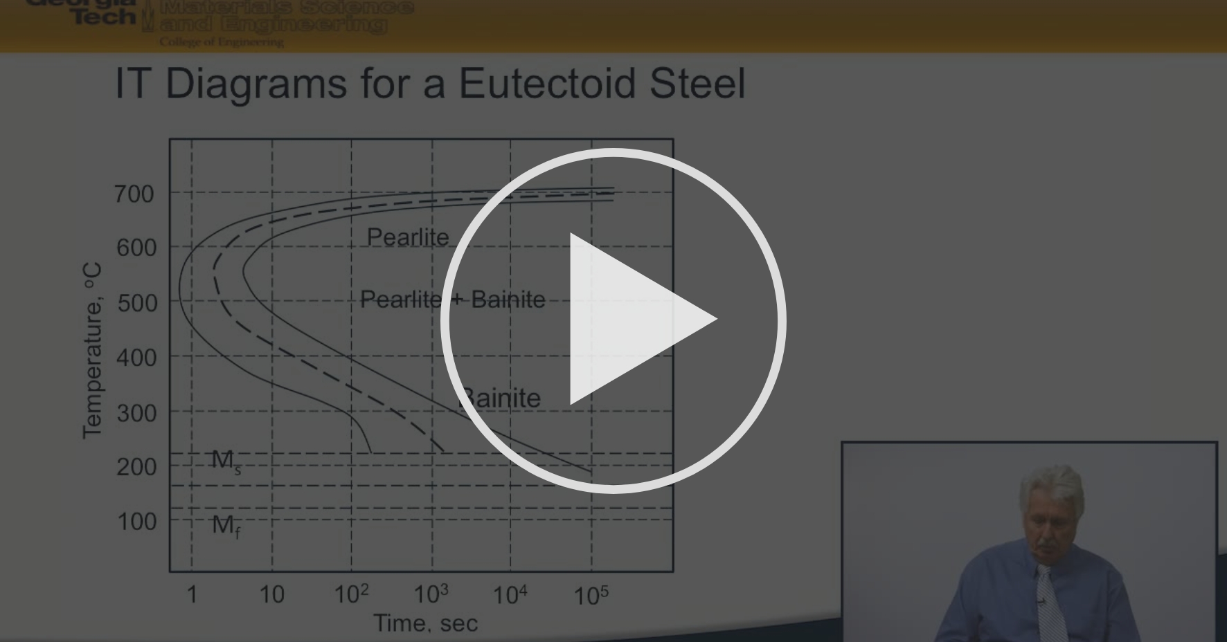
2 25 Isothermal Transformation It Diagrams For A Eutectoid Steel Kinetics Of Structural Transformations Coursera

Question 4 10 Points A Using The Isothermal Transformation Diagram For Iron Carbon Alloy Of Eutectoid Homeworklib

Using The Isothermal Transformation Diagram For An Iron Carbon Alloy Of Eutectoid Composition Specify The Final Microstructure In Terms Of Microconstituents Present And Approximate Percentage Of Each Study Com

Using The Isothermal Transformation Diagram For An Alloy Steel Type 4340 Specify The Nature Of The Final Microstruct Homeworklib
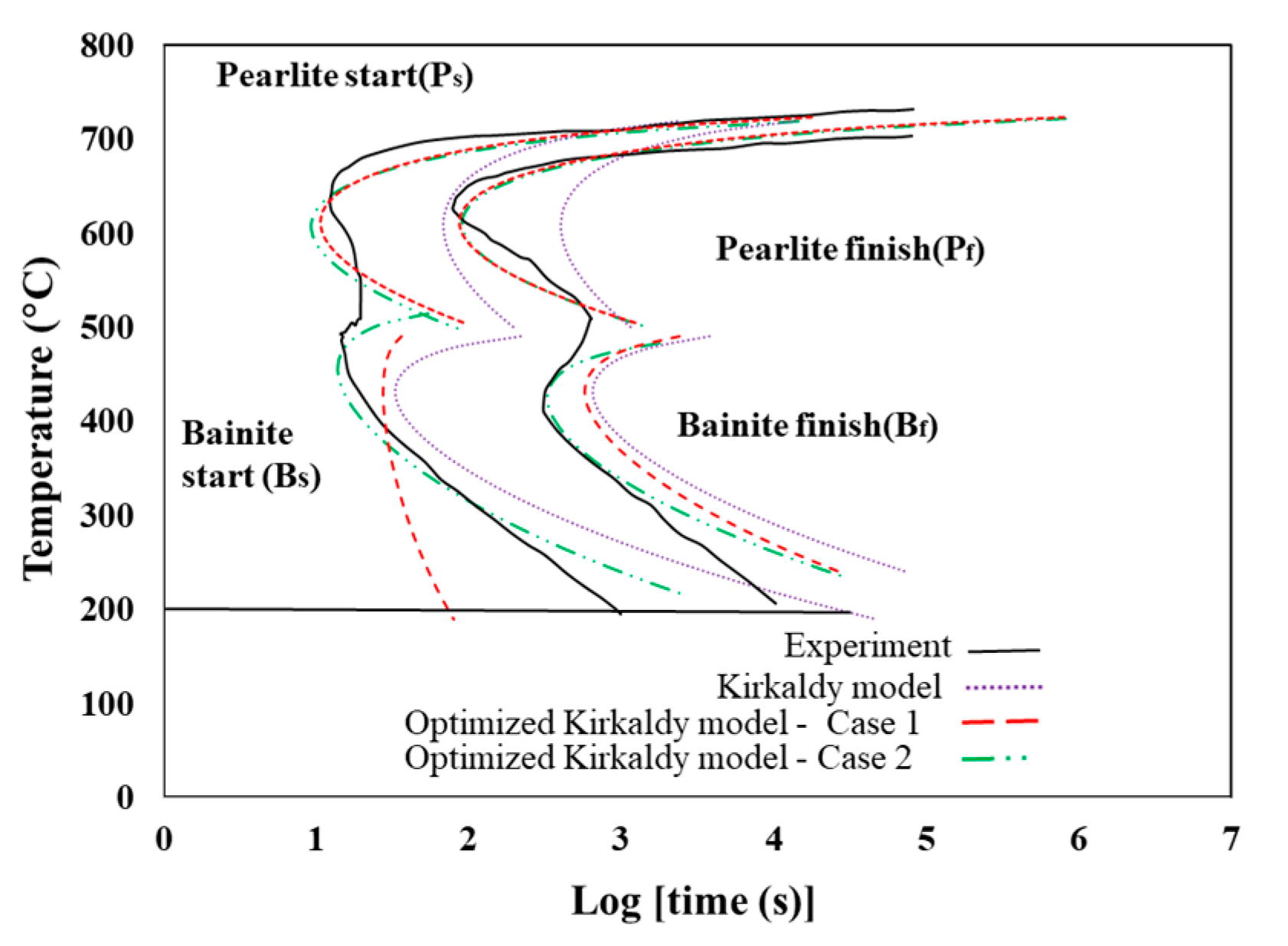
Metals Free Full Text Adjustment Of Isothermal Transformation Diagrams Using Finite Element Optimization Of The Jominy Test










0 Response to "38 using the isothermal transformation diagram"
Post a Comment