38 rf front end block diagram
Simplified Front -End Block Diagram From UMTS to LTE and beyond, the RF component technologies are developed not only to perform the radio conformance test but also to reduce LTE RFFE complexity. This is a unique circuit guide to creating "***Auto Turret Defense Pods***", the garage door protected base defense systems that are featured in many Youtube videos and which I consider essential for any mid to end of wipe base. The purpose of this circuit is to have an automated system to protect the turrets once they run out of ammo. I haven't seen this particular design elsewhere, but I apologize in advance if this is already a common and well publicized build. So let's get into it! Here is...
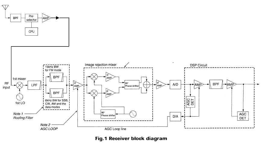
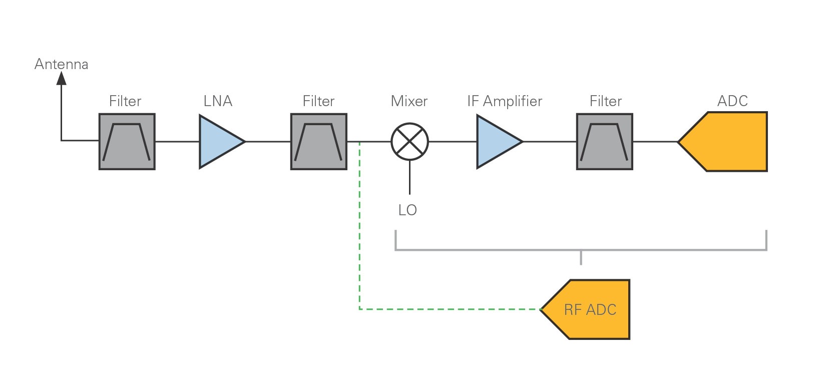
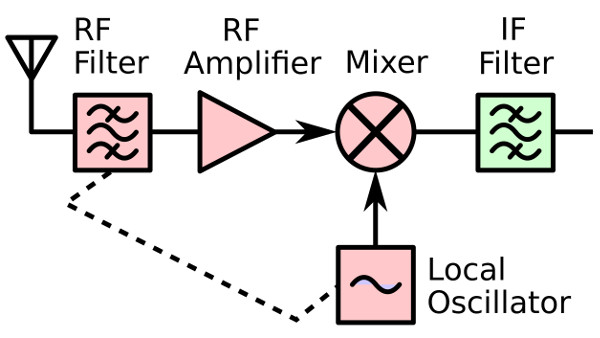
Block diagram of a superheterodyne receiver. The RF front end consists of the components on the left colored red. In a radio receiver circuit, the RF front end is a generic term for all the circuitry between a receiver's antenna input up to and including the mixer stage. It consists of all the components in the receiver that process the signal at the original incoming radio frequency (RF), before it is converted to a lower intermediate frequency (IF).

Rf front end block diagram
Download scientific diagram | The block diagram of RF front-end structure. from publication: Nested Hybrid Cylindrical Array Design and DoA Estimation for ... https://healthimpactnews.com/2018/cell-phone-and-wifi-exposure-to-the-eyes-causes-long-term-damage/ Cell Phone and Wifi Exposure to the Eyes Causes Long-Term Damage The eyes of ten-year-old children absorb five times more cell phone radiation than the eyes of adults, and the eyes of five-year-old children absorb 12 times more than adults. by John P. Thomas Health Impact News Microwave exposure to the eyes causes long-term damage regardless of whether it is coming from smartphones, tablets,... Download scientific diagram | (a) High-level block diagram of the overall RF front-end architecture, (b) a more detailed block diagram of a single RF chain, ...
Rf front end block diagram. The simplified block diagram of a Direct Conversion Receiver front-end is shown in Fig.1 It represents the process of 2.4GHz incoming RF signal frequency (f ... Download scientific diagram | Block diagram of the RF front-end module from publication: Embedded passives on multi-layer printed wiring board (PWB) for ... So I've been messing around with the LoRa technology for a while now, and I've been very impressed with the range these little chips are capable of achieving. To me, the trick to LoRa lies in the extremely sensitive receiver (for such a small and cheap package) as well as the modulation's ability to handle interference quite well. So an idea I've had for a while: Could the range be extended even further by simply designing an up/down converting RF front end for a LoRa IC such as the SX1261... [Here it is.](https://i.imgur.com/CxiNXKy.jpg) In 1986, Nintendo released an add-on called the Famicom Disk System. This allowed the Nintendo Family Computer (Famicom) to play games based from floppy disk. Not only could games be purchased, but so could blank disks which could be written at special kiosks. These kiosks were supported until 2003. If you were not aware, Famicom is the Japanese version of what we know in other parts of the world as the Nintendo Entertainment. The Twin Famicom i...
​ ​ "control" as for the amplifier that controls the signal strength, there are two main functions: 1. Control the signal strength to a certain extent: under normal circumstances, the signal strength received by the antenna cannot meet the needs of information processing, so the amplifier is required to increase the signal strength to a certain extent, the absolute signal strength The unit is DBM, 0 DBM is 1MW, 10 DBM is 10MW, which is logarithmic growth rela... 19 Jul 2020 — The RF front end consists of all circuitry needed to interface between antennas and the digital section in an RF system. The digital block ... So Skyworks is local to me. I have a BSEE... but it seems they only want applicants pursuing a Masters degree/PHD. I've been toying with the thought of learning some of this but it seems like a ton to learn.. especially in 2 years back at a university. Did anyone here get a Masters / PHD and fully understand any of this? The only job I'm somewhat knowledgeable about is the RF ENGINEERING TECHNICIAN. Analog Design was definitely not my strong suit. Neither was RF. But then again I work with RF ... Figure 1. M-MIMO RF front-end block diagram. Wide Operation Bandwidth. ADRF5545A/ADRF5547/ADRF5549 gain characteristics of each device and their respective frequency coverage is shown in Figure 2. Parts are optimized for commonly used cellular bands and aligned with other tuned components used in the same design, such as power amplifiers and filters.
Download scientific diagram | RF front-end schematic. from publication: A 900-MHz transceiver chipset for two-way paging applications | A 900-MHz ... Fig. 1. 4G/5G RF front end diagram. • Improve the power efficiency for mmWave FR2 radios; most probably FR2 will be used mainly for downlink in mobile applications [10, 11]. • Increase the number of antennas to 6-8 with the requirement to reach these antennas from different 4G/5G LTE radios which have to coexist with multiple Download scientific diagram | (a) Simplified block diagram of the RF front-end. (b) Frequency plan. from publication: A 900-MHz transceiver chipset for two-way paging applications | A 900-MHz ... Front End Block Diagram Smartphone 2, 3, and 4G 14 + Bands Typ. –LB 699 to 960 MHz –MB 1428 to 2170 MHz –HB 2300 to 2690 MHz Assumes High Band Module is Separate, but Could be Integrated B8 2, 3, 4G Module LB GGE MB GGE B1 B4 B25 B3 B20 B26 B12 PA Bias and Control MIPI Interface Switch Bias and Control Load Line Match Load Line
SO i just dropped off my car at a shop that will be installing my 280 amp singer alternator today as well as upgrading the stock wires. Real anxious about the whole thing considering how hard I had to look to find someone willing to do this kind of work to this car(a surprising amount of mechanics AND audio installers refused to do one job the other or both due to the complexity of the systems under the hood) and worried about the cost in the end. To help with that I decided to type a rough dr...
Hi everyone, I've translated a Chinese Wild report by Hearth Friends Society, first published 6 March 2021. ####[Decklists and codes](https://imgur.com/a/MHIajZa) ####[Charts](https://imgur.com/a/NnWYiOR) ####[Original source](https://lushi-app.gameyw.netease.com/xiaomei/fetch_news/316144.html) ------------------------ Hello everyone, I am Bing Shuai (冰帅) from Suzhi Jicha (素质极差). The meta this week differs little from last week. Cancer still runs amok at the start of the month, Warlock and...
This guide should hopefully direct you on the right path to getting your Hivemind Mount. Why do we need ***Another*** guide!? Well, sometimes people like to see clarification on certain points where they're unsure on, and sometimes seeing a guide written differently can help! Video if you prefer to watch guides: [https://youtu.be/ju7ZvVUNZb0](https://youtu.be/ju7ZvVUNZb0) Or written guide below: # Points of consideration: * You need a group of 5 people complete this, you cannot solo it. * Yo...
I'm looking for a schematic for RSP1. I looked thru several pdfs on the sdruno site but didn't find one. Just functional block diagrams Mine all of a sudden quit working. From a software aspect it appears that all is good so I am suspicious that the rf front end device may have gotten zapped. Assuming that its a discrete part I was thinking/hoping I might be able to replace it but it would be best to have a look at a schematic to see if there is one there.
Block diagram of RF front end design ... Radio frequency fingerprinting (RFF) could provide an efficient solution to address the security issues in wireless ...
Fig.1 is a simplified block diagram of the proposed RF front-end that is based on the previous work presented in [1]. The first stage of ...
Download scientific diagram | (a) High-level block diagram of the overall RF front-end architecture, (b) a more detailed block diagram of a single RF chain, ...
https://healthimpactnews.com/2018/cell-phone-and-wifi-exposure-to-the-eyes-causes-long-term-damage/ Cell Phone and Wifi Exposure to the Eyes Causes Long-Term Damage The eyes of ten-year-old children absorb five times more cell phone radiation than the eyes of adults, and the eyes of five-year-old children absorb 12 times more than adults. by John P. Thomas Health Impact News Microwave exposure to the eyes causes long-term damage regardless of whether it is coming from smartphones, tablets,...
Download scientific diagram | The block diagram of RF front-end structure. from publication: Nested Hybrid Cylindrical Array Design and DoA Estimation for ...
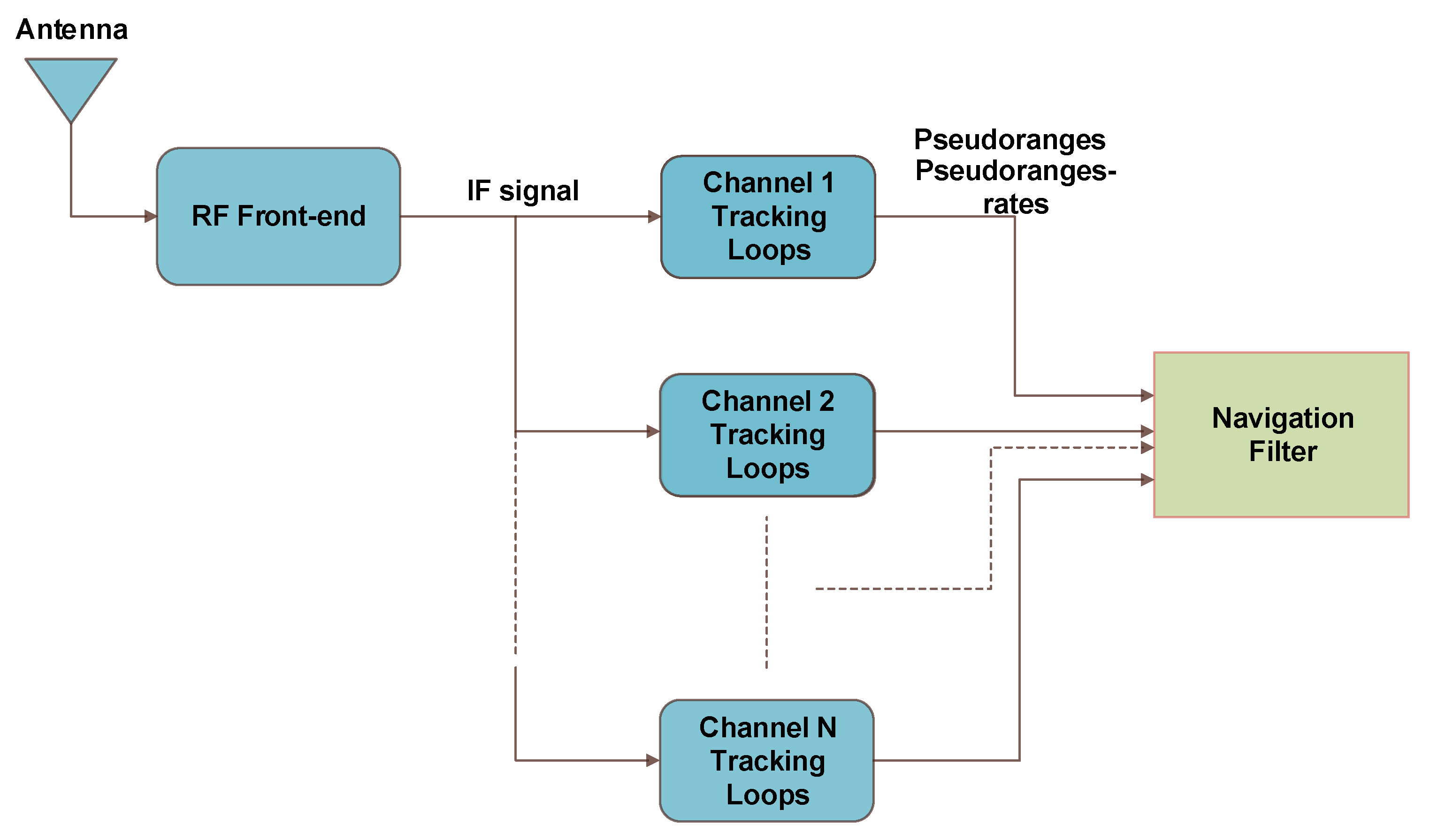
Applied Sciences Free Full Text An Efficient Ultra Tight Gps Riss Integrated System For Challenging Navigation Environments Html

Figure 15 Analysis Of Rf Front End Performance Of Reconfigurable Antennas With Rf Switches In The Far Field
Emb2538pa Ieee 802 15 4 Zigbee Radio Frequency Module Block Diagram Embit Srl Embedded Wireless Solutions

Figure 1 From A 0 25 Spl Mu M Cmos Rf Front End With A Low Cost Patch Antenna For Gps Receivers Semantic Scholar

Figure 1 From Highly Integrated Rf Frontend Module For High Shf Wide Band Massive Mimo In 5g And Switching Mode Amplifiers Beyond 4g Semantic Scholar

Figure 1 Implementation Of Low Cost Uhf Rfid Reader Front Ends With Carrier Leakage Suppression Circuit

Sensors Free Full Text Toward Realization Of 2 4 Ghz Balunless Narrowband Receiver Front End For Short Range Wireless Applications Html
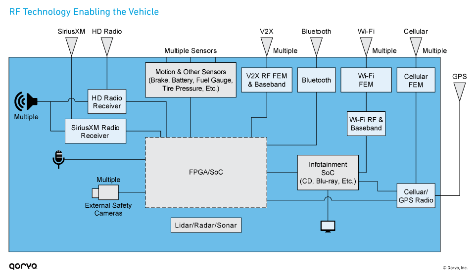

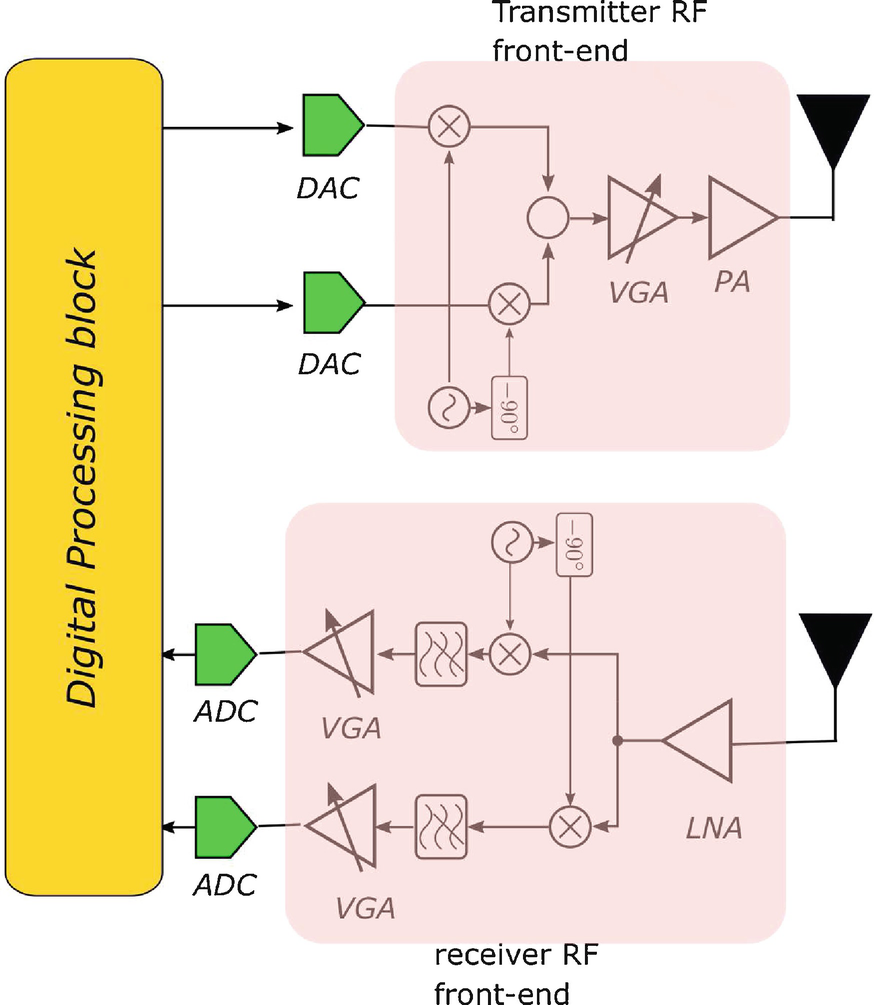


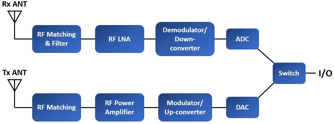








0 Response to "38 rf front end block diagram"
Post a Comment