38 paragon defrost timer 8145 20 wiring diagram
How to test Paragon 8145-20 defrost timer. Timer dial rotates continuously, and keeps good time. X-3596 Trippers are attached to edge of dial. When.1 page Find solutions to your paragon defrost timer 20 wiring diagram question. Get free help, tips & support from top experts on paragon defrost timer Adjustable Defrost Cycle Duration: 4 to minutes in S and Paragon Wiring Diagrams Electric Heat Defrosting S & S Series. how to test paragon 20 defrost timer rh waterheatertimer org Paragon 20 Wiring Schematic Paragon Time Clock tors, Paragon ...
Paragon 8145 20 Wiring Diagram – wiring diagram is a simplified gratifying pictorial representation of an electrical circuit. It shows the components of the circuit as simplified shapes, and the knack and signal connections amongst the devices. A wiring diagram usually gives opinion very nearly the relative point and settlement of devices and ...

Paragon defrost timer 8145 20 wiring diagram
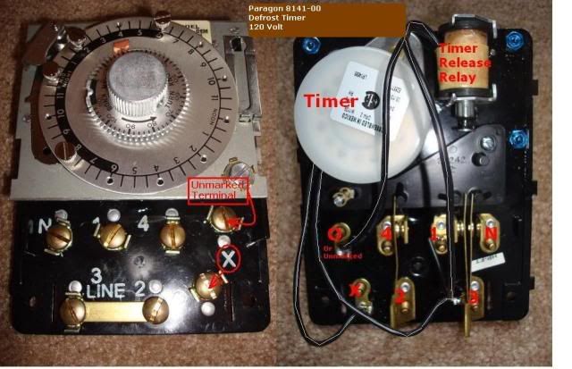
8145 20 Timer Wiring Diagram. S and Paragon Available in 6-pack display. Wiring Diagrams Electric Heat Defrosting S & S Series. COMP. HEATER. FAN. L N. The Paragon® defrost and the Tork® electric timers offer versatility and unbeatable Electric Heat,. Hot Gas or Compressor Shutdown. Paragon 8145 20 defrost timer wiring diagram. It reveals the elements of the circuit as simplified forms and also the power and also signal connections between the tools. Collection of paragon defrost timer 8145 20 wiring diagram. 8047 20 208 240 for electric heat defrosting auxiliary contact models 50 hz available open open closed 4 110 min. Description: Paragon Defrost Timer Wiring Diagram Paragon Defrost Timer Wiring regarding 8145 20 Wiring Diagram, image size 577 X 600 px, and to view image details please click the image.. Here is a picture gallery about 8145 20 wiring diagram complete with the description of the image, please find the image you need. We hope this article can help in finding the information you need. 8145 20 ...
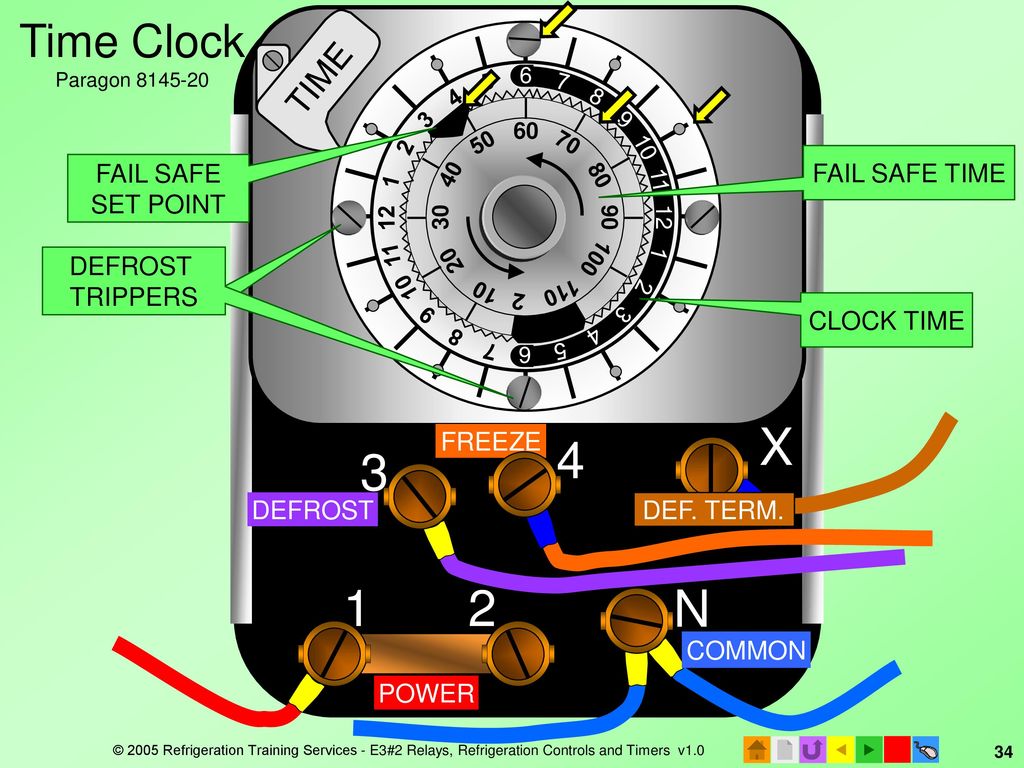
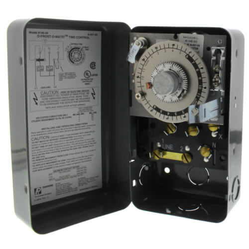
Paragon defrost timer 8145 20 wiring diagram. The Paragon® 8000 Series Auto Voltage Defrost Timer is designed ... Wiring Diagrams. 8047-00 and 8047-20. Electric Heat Defrosting. 8145-AV. 8145-AV50. www.robertshaw.com. Customer Service 1.800.304.6563. REFRIGERATION. D4. Product Drawings. 8047-00 and 8047-20. Electric Heat Defrosting. 8145-AV.3 pages I cant seem to find a wiring diagram on how to wire this correctly Link below has wiring diagrams and wiring manuals for V Paragon - /V Defrost Timer - Designed for commercial freezers and refrigerators, Paragon commercial defrost controls provide automatic defrost capability. Paragon 20 Wiring Diagram - Wiring Diagram Pdf Free Paragon 20 ... The DTAV40 may also be used to replace Paragon and Precision series time terminated defrost . Paragon Defrost Timer Wiring Walk In Freezer Car Diagrams. Grasslin defrost timer wiring diagram book of paragon 20 dia arcnx paragon defrost timer wiring diagram clock and freezer to 20 paragon defrost timer wiring diagram fresh 20 questions answers with.
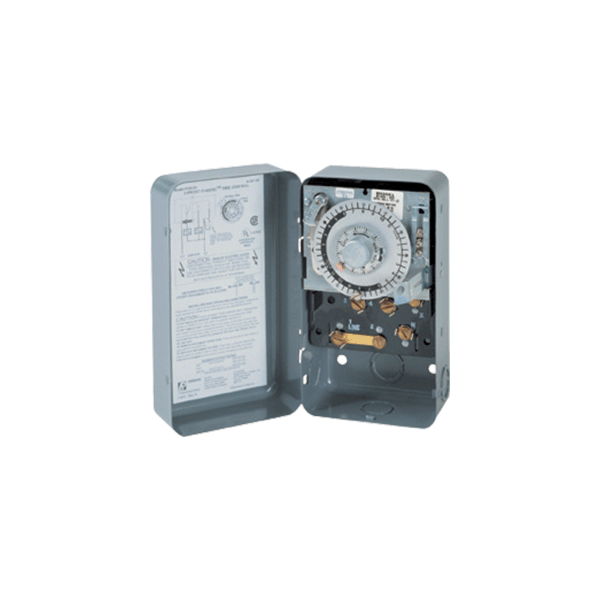
28 Jan 2010 — wiring diagram for paragon defost timer 8145-20 & 8145-10 - Paragon 8145-20 Defrost Timer question. 8047-20 208-240 For Electric Heat Defrosting (Auxiliary Contact Models), 50 Hz available Open Open Closed 4-110 Min. MECHANICAL DEFROST TIMER 8000 Series Defrost Duration Solid Copper Contacts Line Voltage – 120/208-240V AC 40 Amp, 2 HP Pins Indicate Defrost Start Time Time of Day Model Number Time Initiated, Time Terminated Time Initiated ... Aviation History magazine is an authoritative, in-depth history of world aviation from its origins to the Space Age. Aviation History offers air enthusiasts the most detailed coverage of the history of manned flight, with action-packed stories and illustrations that put the reader in the cockpit with pilots and military (Army, Navy, and Marines) aviators to experience aviation’s greatest dramas. Collection of paragon defrost timer 8145 20 wiring diagram. A wiring diagram is a simplified traditional photographic depiction of an electrical circuit. It reveals the elements of the circuit as streamlined shapes, and also the power as well as signal links in between the tools.
A diagram showing how to switch wires from. 6 days ago november 22nd i have a paragon 20 defrost timer do you wire the compressor to the timer i cant seem to find a wiring diagram on. Here is a picture gallery about 8145 20 wiring diagram complete with the description of the image please find the image you need. P PARAGON. 8000. Series. MECHANICAL. DEFROST. TIMER ... 8141-20. SLINE 2. 8143-00. 8143-20. 8145-00. 8145-20. Solid Copper. Contacts. Line Voltage -.4 pages Description: Paragon Defrost Timer Wiring Diagram Paragon Defrost Timer Wiring regarding 8145 20 Wiring Diagram, image size 577 X 600 px, and to view image details please click the image.. Here is a picture gallery about 8145 20 wiring diagram complete with the description of the image, please find the image you need. We hope this article can help in finding the information you need. 8145 20 ... Paragon 8145 20 defrost timer wiring diagram. It reveals the elements of the circuit as simplified forms and also the power and also signal connections between the tools. Collection of paragon defrost timer 8145 20 wiring diagram. 8047 20 208 240 for electric heat defrosting auxiliary contact models 50 hz available open open closed 4 110 min.
Heating Air Refrigeration Discussion Hvac Talk
8145 20 Timer Wiring Diagram. S and Paragon Available in 6-pack display. Wiring Diagrams Electric Heat Defrosting S & S Series. COMP. HEATER. FAN. L N. The Paragon® defrost and the Tork® electric timers offer versatility and unbeatable Electric Heat,. Hot Gas or Compressor Shutdown.
2

Solved Paragon 8141 00 Defrost Timer Wont Turn Fixya
8145 20 Paragon 8145 20 208 240v Defrost Timer
2
2
E3 Hvacr Controls And Devices Ppt Download
2
2

Paragon 8145 20 Wiring Diagram Nicolstalker

Timers Paragon Electrical
8145 20 Paragon 8145 20 208 240v Defrost Timer

Paragon Part 8145 20m Paragon Defrost Timer Model 8145 20 Mechanism Only Refrigerator Freezer Repair Parts Home Depot Pro
2
Paragon 8145 20 8145 20 Paragon Electric Co Field Controls Defrost Cntrl Temp Press Robertshaw Paragon Defrost Time Time Clock Meier Supply Co Inc
Robertshaw Com

Paragon 8000 Series English Pdf Switch Timer
Paragon

Wiring Diagram With Timer Ztxxxx
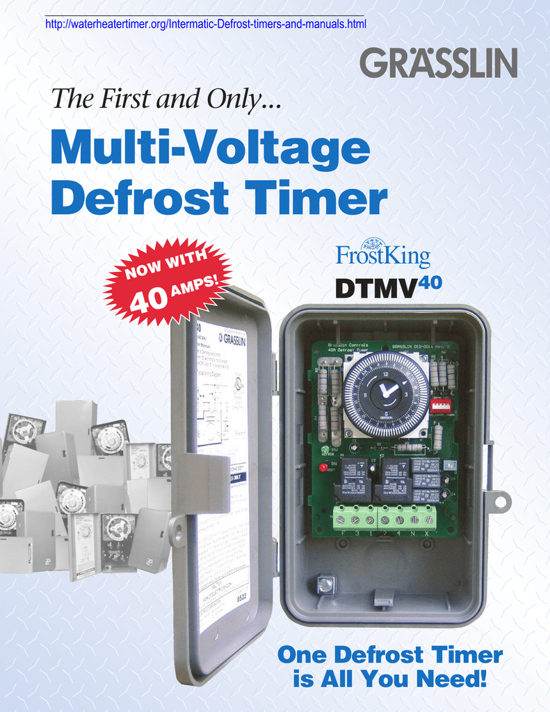
Multi Voltage Defrost Timer 40 The First And Only

Paragon 8145 20b 208 240v Defrost Timer W Bracket Pg 8145 2
2

Freezer Follow Up Youtube
2

Solved Hi Would Like To Put Timer In Service Mode To Fixya

Paragon Replacement

Intermatic Product Catalog Pages 101 150 Flip Pdf Download Fliphtml5

Answered Paragon 8145 20 Defrost Timer Questions Issues Page 2 Fixya

Mcquay Calc Resist Evap Pdf

Paragon 8145 20b Defrost Control 208 240v

Klv Low Velocity Evaporators Product Data Amp Applications Manualzz
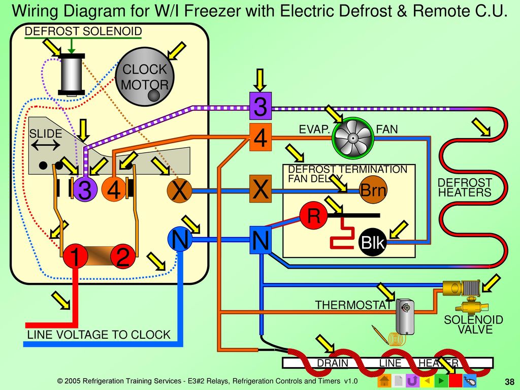
E3 Hvacr Controls And Devices Ppt Download
2

Supco S8145 00 Complete Commercial Defrost Timer Replaces Paragon 8145 00 Timers Electrical Fcteutonia05 De
2

Paragon Defrost Timers 8145 And 9145 Overview By Mike Shelton
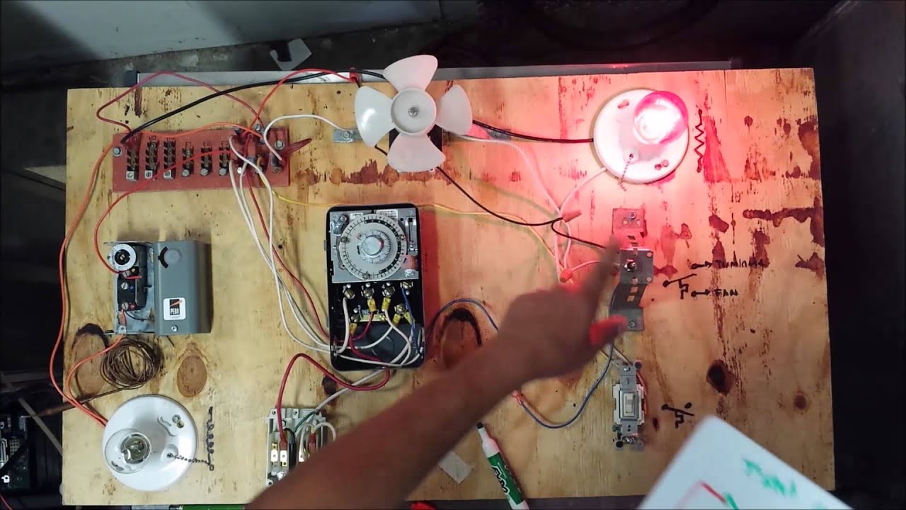
Freezer Defrost Timer Live Operation Youtube
2
0 Response to "38 paragon defrost timer 8145 20 wiring diagram"
Post a Comment