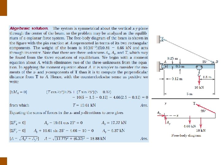
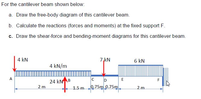
38 draw the free-body diagram for the cantilevered beam. a is the a fixed support.
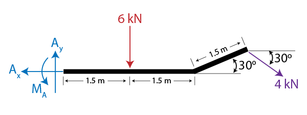
The cantilevered beam is embedded into a fixed vertical wall at \(A\text{.}\) Draw a neat, labeled, correct free-body diagram of the beam and identify the knowns and the unknowns. ... The wall at \(A\) is a fixed support which prevents the beam from translating up, down, left or right, ... To draw the free body diagram, ... In the last decade, an enormous amount of attention has been paid to piezoelectric harvesters due to their flexibility in design and the increasing need for small-scale energy generation. As a result, various energy review papers have been presented by many researchers to cover different aspects of piezoelectric-based energy harvesting, including piezo-materials, modeling approaches, and ...
Angular for Material Design Leverage Angular Material and TypeScript to Build a Rich User Interface for Web Apps
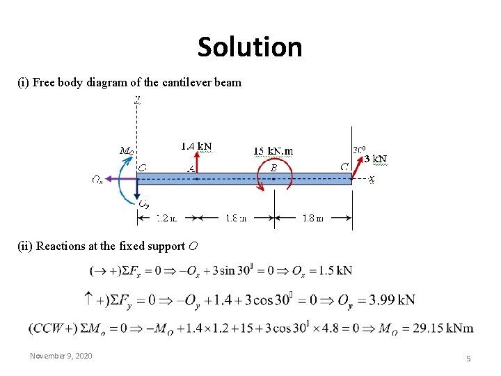
Draw the free-body diagram for the cantilevered beam. a is the a fixed support.
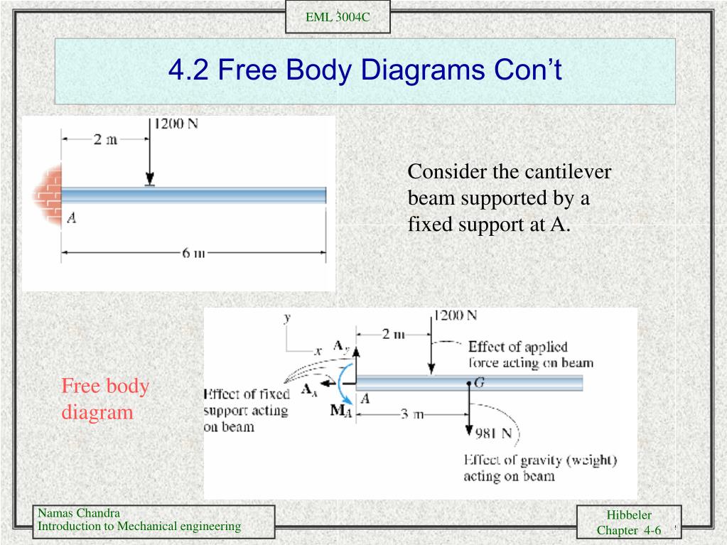
DRAW THE FREE BODY DIAGRAM (FBD) 4) wi fa em +। 30 450 5. mi it m2 m3 m4 4 0 answers (b) Forced harmonic displacement may be represented by the steady state component as: *(t) = (xsto sinut Where: (Xst), is the maximum static deformation w is the frequency of the forcing function Wy i The beam shown in the figure below (figure 1) is subjected to a moment of m 30 knm . L is the span for calculating the beam moment. 33 Flexural Stress ENES 220 ©Assakkaf Flexural Normal Stress – The resisting moment M r that can be develop by the normal stress in a typical beam with loading in a plane of symmetry but arbitrary cross section (Fig. Figure 1. 0 m to the left hand support is ... Nov 20, 2021 · This is done using a free body diagram of the entire beam. 7-51 Complete Problem 7-51 from your Hibbeler textbook with all of the following modifications: (A) Replace the support reactions (pin at A and roller at B) with a single fixed support at point A (B) Determine the equations for internal shear (V) and 7. 23 (c) 40.
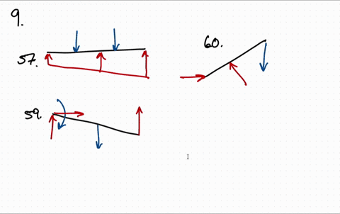
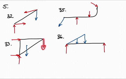
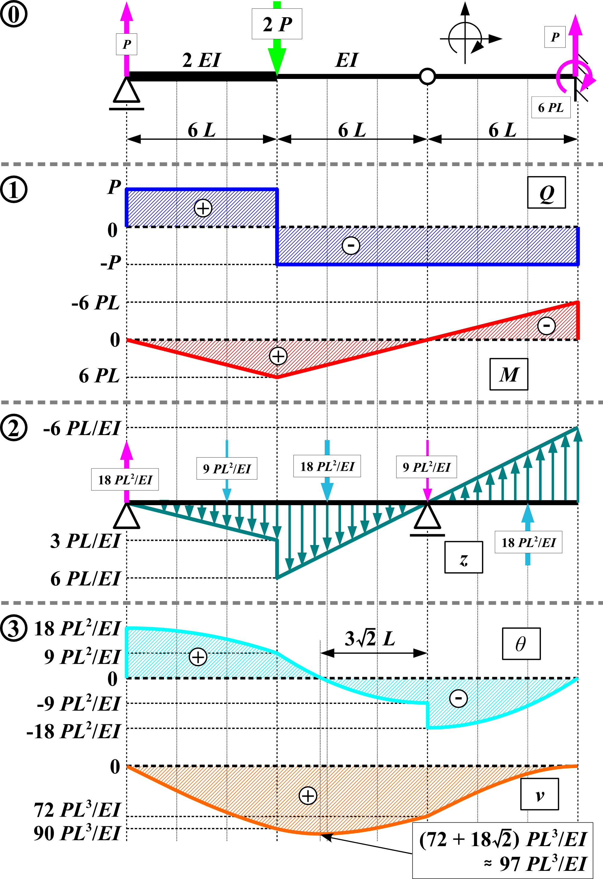
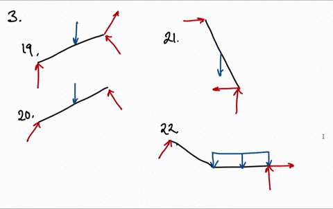
Draw the free-body diagram for the cantilevered beam. a is the a fixed support.. 11、If you want to put out a fire, you may draw water from a _____ in the street. A、hydrant B、thermos C、spittoon D、basin 12、We have stored a lot of _____ vegatables for the winter. A、counterfeit B、sightly C、dehydrated D、sour 13、Most of the children are in favor of going to the _____, for they are interested in living fish ... When drawing the moment diagram, one of two sign conventions is. ... free-body diagrams of each member are drawn, F ig. 4-18 c.T h e. ... diagram for each cantilevered beam is drawn, Fig. 4-21 b, the superposition. of these diagrams yields the resultant moment diagram for the simply. Draw the moment diagram for the cantilevered beam. ... The beam in the figure is fixed at A, simply supported (roller support) at C and contains a frictionless pin at B. ... For the beam shown, (a ... Cantilever beam calculation example
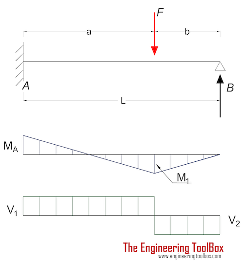
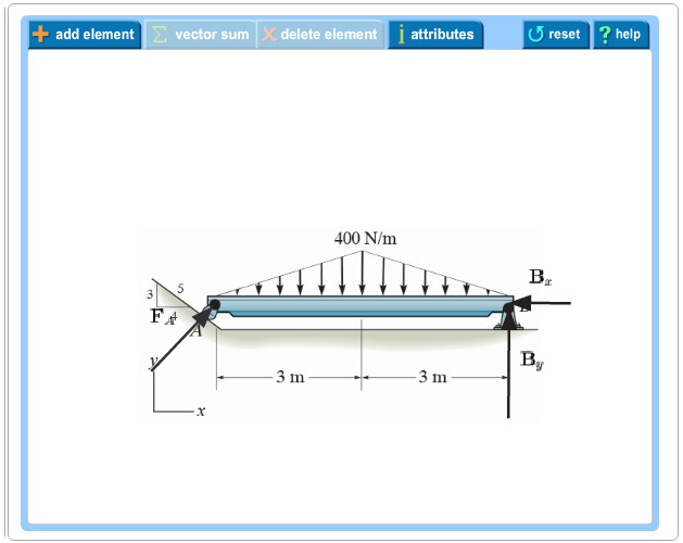
Nov 19, 2021 · Find the moment diagram for this beam as in Figure 1-31(c). BEAMS DEFLECTION. You either need to have fixed support or have a back span and check for the uplift of the far support. Determine theCantilever Beam Analysis through APDL: Perform static structural finite element analysis of cantilever beam as shown in figure 1. Determine the components of the support reactions at the fixed support a on the cantilevered beam Determine the components of the support reactions at the fixed support a on the cantilevered beam ... provide graphical descriptions of how the internal shear and moment vary throughout the beams length. 4 m Determine the smallest diameter of the shaft using the maximum-shear-stress theory, with 10 PROBLEM-4 Support reactions are calculated and shown on the free-body diagram of the shaft. Draw the shear force and bending moment diagrams for ... Cerca nella rete #adessonews. carca in questo sito. Generic selectors
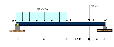
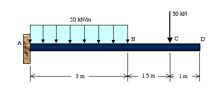
Author Gravatar is shown here. Clickable link to Author page. Article by: fojon Authors link to author website or other works. fojon Opened on May 24, 1883, the Brooklyn Bridge was the first fixed crossing of the East River. It was also the longest suspension bridge in the world at the time of its opening, with a main span of 1,595.5 feet (486.3 m) and a deck 127 ft (38.7 m) above mean high water. Mar 05, 2021 · Free-body diagram. The free-body diagram of the beam is shown in Figure 4.10a. Support reactions. The reactions at the support of the beam can be computed as follows when considering the free-body diagram and using the equations of equilibrium: Shearing force and bending moment functions of beam BC. 0 < x 1 < 3. V = 0. M = 0. 3 < x 2 < 6. V ... Draw the free body diagrams of the major shaft and parts in the problem. If the load is not defined in the problem, use the maximum bearin inn WA 由 Jot WN DER Rotary kilns for cement production can extend over a length of 150 m or more. The support rollers are spaced at about 30 m intervals. shaft can be displaced relative to the hou
Problem 9 1 Two Beam Segments Ac And Cd Are Connected Toge the r At C By A Frictionless Pin Segment Is Cantilevered From R. 329 6 1 Draw The Shear And Moment Diagram s For Shaft Bearings At A B Exert Only Vertical Reactions On. A beam is shown in the figure below. (Figure 1) Part A : Draw the shear diagram for the beam.
Draw the shear and moment diagrams for the beams shown below . x 0. Calculate the support reactions and draw the Bending Moment diagram, Shear Force Diagram, Axial Force Diagram. Problem 3 3. Jan 06, 2021 · Shear and Bending Moment diagrams are drawn as shown below.
Nov 20, 2021 · This is done using a free body diagram of the entire beam. 7-51 Complete Problem 7-51 from your Hibbeler textbook with all of the following modifications: (A) Replace the support reactions (pin at A and roller at B) with a single fixed support at point A (B) Determine the equations for internal shear (V) and 7. 23 (c) 40.
The beam shown in the figure below (figure 1) is subjected to a moment of m 30 knm . L is the span for calculating the beam moment. 33 Flexural Stress ENES 220 ©Assakkaf Flexural Normal Stress – The resisting moment M r that can be develop by the normal stress in a typical beam with loading in a plane of symmetry but arbitrary cross section (Fig. Figure 1. 0 m to the left hand support is ...
DRAW THE FREE BODY DIAGRAM (FBD) 4) wi fa em +। 30 450 5. mi it m2 m3 m4 4 0 answers (b) Forced harmonic displacement may be represented by the steady state component as: *(t) = (xsto sinut Where: (Xst), is the maximum static deformation w is the frequency of the forcing function Wy i


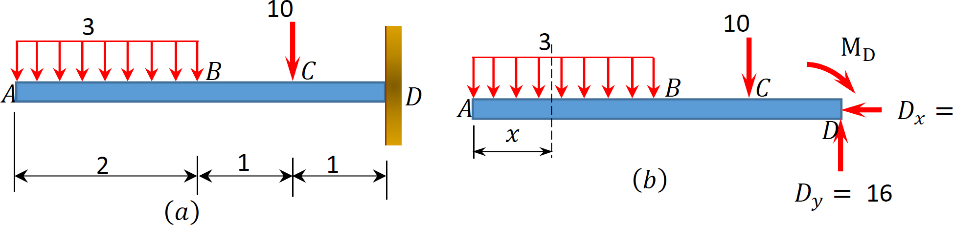


0 Response to "38 draw the free-body diagram for the cantilevered beam. a is the a fixed support."
Post a Comment