37 ge shunt trip breaker wiring diagram
Variety of ge shunt trip breaker wiring diagram. A wiring diagram is a simplified traditional pictorial depiction of an electric circuit. It reveals the elements of the circuit as simplified forms, as well as the power and signal connections in between the gadgets. April 12, 2020. · Wiring Diagram. by Anna R. Higginbotham. shunt trip breaker wiring diagram - You'll need an extensive, skilled, and easy to understand Wiring Diagram. With this kind of an illustrative manual, you are going to be able to troubleshoot, prevent, and complete your assignments easily. Not merely will it help you accomplish ...
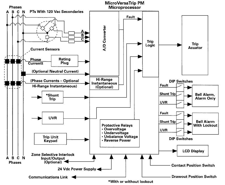
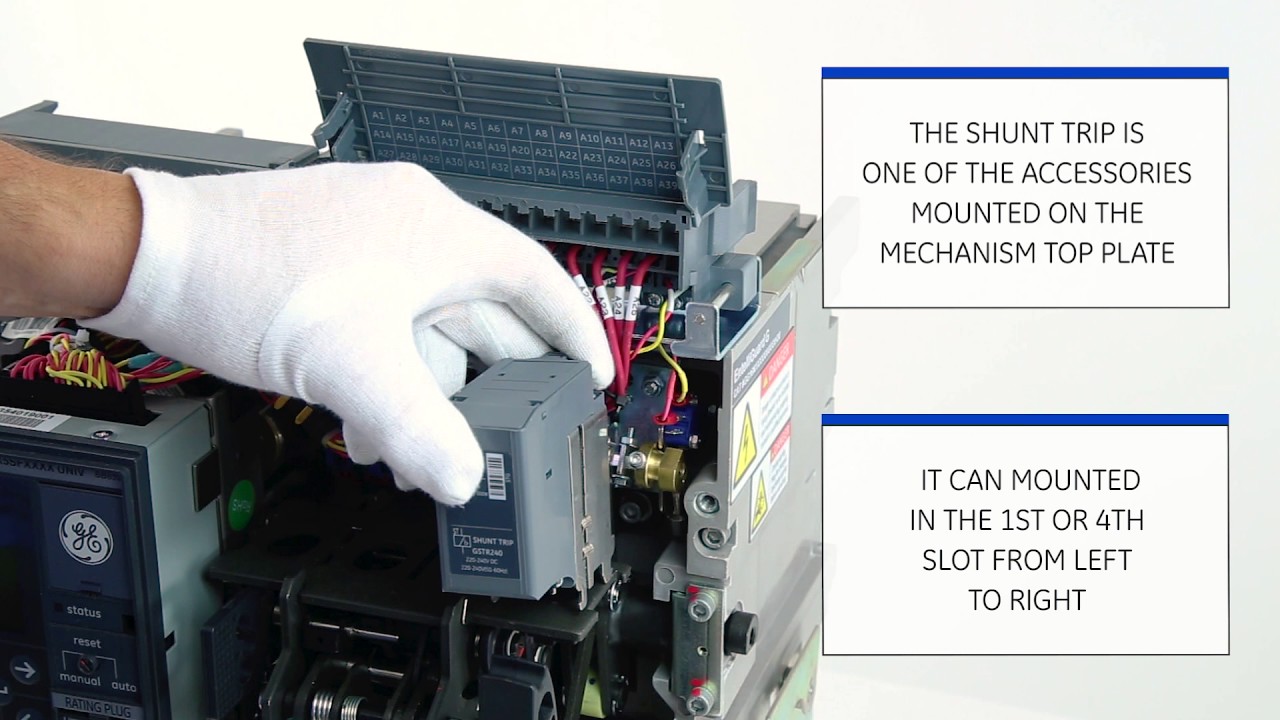
The SAST1 shunt trip provides remote tripping of the breaker when used with a momentary close contact. Not recommended for use with a latching relay contact since electronics in the shunt trip will pulse power to the coil if continuously energized, and breaker shunt tripping upon reclosure will be delayed 1-2 seconds at rated control voltage.
Ge shunt trip breaker wiring diagram
Trip currents of 5-60, 30-360, or 100-1200 A. Time delay from 0.10 to 1 second. (Adjustable) Input Power 2 VA plus shunt coil requirements. Rated @ 120 Vac. Input Withstand 200,000 Amp. RMS for 3 cycles, 50/60 Hz Model BGFL (Relay) Ground Fault Current Detection Systems Trip Currents 5- 60, 30- 360, or 100 -1200 A Internal Circuit Options Shunt Trip Breaker Wiring Diagram For Ansul System - You almost certainly already know that square d shunt trip breaker wiring diagram has become the hottest topics over the internet today. Based on the information we took from google adwords, square d shunt trip breaker wiring diagram has very much search online web engine. Wiring Diagram 2 Pole Gfci Breaker Fresh Circuit Breaker Diagram Fresh Wiring Diagram Shunt Trip Breaker. We collect a lot of pictures about Square D Shunt Trip Breaker Wiring Diagram. and finally we upload it on our website. Many good image inspirations on our internet are the best image selection for Square D Shunt Trip Breaker Wiring Diagram ...
Ge shunt trip breaker wiring diagram. (3) this drawing depicts standard wiring diagram only. (4) definitions: e/o-electrically operated circuit breaker; m/o-manually operated circuit breaker. (5) m/o bkrs with remote close option (with one shunt trip device) and all e/o (with one shunt trip device only) require a 4-stage (minimum) auxiliary switch. (6) two shunt trip devices ... Ge Shunt Trip Breaker Wiring Diagram. Assortment of ge shunt trip breaker wiring diagram. A wiring diagram is a streamlined standard photographic representation of an electrical circuit. It shows the elements of the circuit as simplified shapes, as well as the power as well as signal connections in between the gadgets. A wiring diagram normally offers… Eaton Cutler Hammer Ch290st Type Ch Breaker 90a 2 Pole 120 240v 10k W Shunt Trip. Cheap Shunt Trip Circuit Breaker Wiring Diagram Find Deals On Line At Alibaba Com. Eaton Ch320st Breaker 20a 3p 120 240v 10 Kaic Type Ch Shunt Trip Rexel Usa. Madcomics shunt trip breaker wiring br120st eaton type br brkr 20a 1 pole circuit breakers thermal ... A shunt trip device is an optional accessory in a circuit breaker that mechanically trips the breaker when power is applied to the shunt trip terminals. The power. In this video i complete explain the shunt trip breaker wiring diagram or In the shunt trip breaker diagram i control the shunt trip coil breaker.
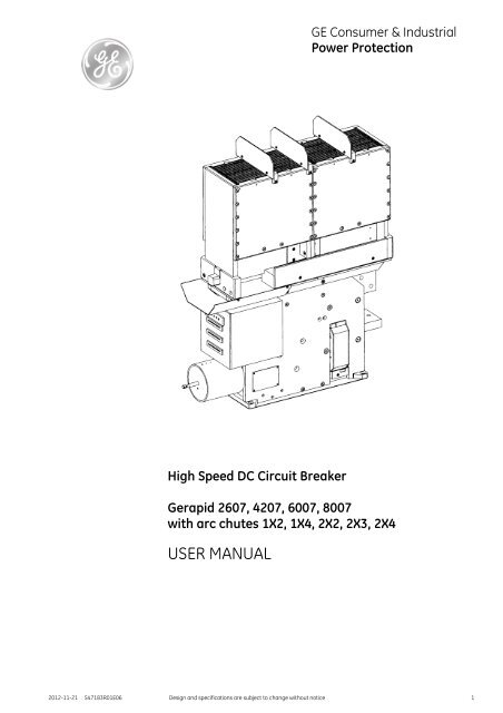
Ansul System Wiring Diagram . Freezer wiring diagram ansul system wiring diagram pdf hood and ansul wiring schematic for rtus ktm duke 125 wiring diagram ansul shut down wiring-diagram shunt trip breaker wiring diagram for hood pt100 3 wire wiring diagram microswith ansul system wiring diagram 1.2.infection-nl.de Collection of ge shunt trip breaker wiring diagram. A wiring diagram is a streamlined traditional pictorial representation of an electrical circuit. It shows the elements of the circuit as streamlined forms, and the power as well as signal connections between the devices. If it is a shunt trip you apply power to trip the breaker. Most X-ray manufacturers spec a control transformer fed off of the breaker you are controlling. That way your emergency shutoff will work without worry that the control circuit has been shutoff. If it is a Ge X-ray room they provide a breaker with the control transformer included. II Circuit Breakers. Basic Configuration. In 1965 GE pioneered the design of insulated case circuit breakers when it introduced the original Power Break circuit breaker . Now, GE introduces Power Break II insulated case circuit breakers, the vanguard of a new age in reliable, flex-ible and easy-to-use circuit protection .
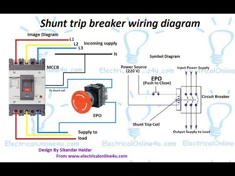
Diagram shunt breaker wiring circuit trip madcomics ge mini qo 20a 1 pole fastest define on a edb eaton br thermal magnetic motor mechanism how to wire. Qob1201021 Mini Circuit Breaker Qo 20a 1 Pole 120 240vac 10ka Bolt On Mount Ac Shunt Trip Schneider Electric Canada. Shunt Breaker Wiring Diagram Shunt Trip Circuit Breaker Wiring Diagram Luxury Ge Shunt Trip. Shunt Breaker Wiring Diagram- wiring diagram is a simplified usual pictorial representation of an electrical circuit. It shows the components of the circuit as simplified shapes, and the capacity and signal contacts amongst the devices. ... Ge Shunt Trip Breaker Wiring Diagram- wiring diagram is a simplified pleasing pictorial representation of an electrical circuit.It shows the components of the circuit as simplified shapes, and the faculty and signal contacts in the company of the devices. Shunt Trip Breaker Wiring Diagram with EPO Button. In this post i am just tell you about wiring of single EPO button with shunt trip MCCB breaker. In industrial state, Electric operator duty is to operate the machinery and his duty is on the front of Main panel board.
Series G Circuit Breakers Molded Case Circuit Breakers Eaton
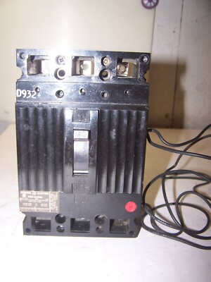
Shunt Trip Breaker. Shunt 120V Operating Voltage. 20 Amps. 3 Pole. 120/240V. Thermal Magnetic Type. 3 Inch W X 2 3/8 Inch D X 3 9/32 Inch H Size. Al/Aq/Alc/Aqc/Spectra Series Panelboard, Residential Load Center Used On. 14 To 8 Awg (Copper), 12 To 8 Awg (Aluminum) Wire Size.
Ge Consumer Amp Industrial G E Power Controls
CASService explains how to wire a shunt trip breaker or contactor to an exhaust hood control package. For questions, please contact CASService at 1-866-784-6...

Step 1 Unpack And Inspect Step 2 Breaker Status Step 3 Installation Ge Industrial Solutions Record Plus Shunt Trip And Undervoltage Release User Manual Page 2 4
From the other side of the "dry" contact, connect a wire to another circuit breaker in the electrical panel to supply power for the trip circuit. What happens here is: From the separate circuit breaker you are feeding power through the ""dry" contact (auxiliary) on the Ansel system to the trip coil located inside the shunt circuit breaker.

Internal Shunt Wiring Diagram Auto Electrical Wiring Diagram
In the above MCCB shunt trip breaker wiring diagram. The incoming 3 phase 4 wire system supply shown. The shunt breaker is 3 pole. Which is used for the 3 phase system. But the coil of the shunt is 220 VAC. So neutral is required also. The neutral wire is connected to the shunt coil. And line wire is controlled with a kill switch.
Power Break Ii Get 8052c 1000486169 Catalog
A wiring diagram is a simplified traditional pictorial depiction of an electric circuit. 1 A shunt trip breaker is a breaker with a solenoid to trip when power is applied to the solenoid. Variety of ge shunt trip breaker wiring diagram. If it is a Ge X-ray room they provide a breaker with the control transformer included.
Library E Abb Com
shunt trip, and overcurrent trip switch warning (1)only qualified electrical personnel should be permitted to work on the equipment. (2)always de-energize primary and secondary circuits if a circuit breaker cannot be removed to a safe work location. (3)drawout circuit breakers should be levered (racked) out to the disconnect position.

Wiring Diagrams For Masterpact Nt Circuit Breakers The Bypass Circuit Through Terminal C2 A2 Is
Shunt Trips Trip Circuit Breakers Relectric. S29386 Circuit Breaker Shunt Trip 110 130v Ac Schneider Electric Canada. Motor Mechanism. Diagram 25 Amp Breaker Wiring Full Version Hd Quality. Diagram Dodge Dart Shunt Wiring Full Version Hd Quality. China Shunt Release Trip Sht For Molded Case Circuit Breaker Mccb.
Ge General Electric 60 Amp Circuit Breaker 480 Vac 3p Ted134060 With Shunt Trip 783164063882 Ebay
This circuit breaker wiring diagram illustrates installing a 20 amp circuit breaker for a 240 volt circuit. The 12/2 gauge cable for this circuit includes 2 conductors and 1 ground. The white wire is used for hot in this circuit and it is marked with black tape on both ends to identify it as such. A neutral wire is not used in this circuit.

35 Trends For Shunt Trip Breaker Wiring Diagram Schneider Stephan Fuchs
Shunt-trip circuit breakers can be used to automatically disconnect a Install the breaker in the panel and wire up the three phases to the three. Need direction to wire a GE TQSTA1 shunt-trip breaker for anselll system - Answered by a verified I will draw up a simple diagram and scan to my computer.Apr 06, · Now I have a GE 20 amp v snap in ...

Wiring Diagrams For Masterpact Nt Circuit Breakers The Bypass Circuit Through Terminal C2 A2 Is
Shunt Trip Breaker Wiring Diagram. Oleh Anonim Maret 28, 2020 Posting Komentar. Ge Shunt Trip Wiring Diagram Catalogue Of Schemas Square D Kal36200 W Shunt Trip Circuit Breaker Circuit Diagram Software Mac Fresh Wiring Program Freeware 6f33e 2 Wire Thermostat Wiring Diagram Shunt Trip Breaker 128 Best Auto Manual Parts Wiring Diagram Images ...
.JPG)
0209b8104g002 Ge General Electric 125vdc Shunt Trip Coil Assembly 5 Cycle For Vb1 With Ml 18
The ones I've used take an extra breaker space, so a single pole 15A breaker shunt trip breaker takes the same space as a 2 pole breaker, a 2 pole takes the space of a 3 pole and so on. Also, in the applications I use them for, the breaker with the circuit that feeds the shunt coils are normally locked on so they can't be turned off ...

Shunt Trip Breaker Wiring Youtube
Wiring Diagram 2 Pole Gfci Breaker Fresh Circuit Breaker Diagram Fresh Wiring Diagram Shunt Trip Breaker. We collect a lot of pictures about Square D Shunt Trip Breaker Wiring Diagram. and finally we upload it on our website. Many good image inspirations on our internet are the best image selection for Square D Shunt Trip Breaker Wiring Diagram ...
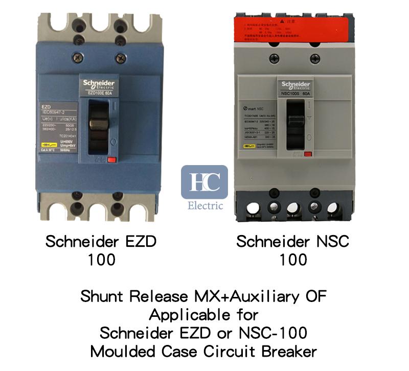
Shunt Trip Resistor 35 Images Mx Shunt Trip Release Applicable For Easypact Squared Ezd Mx Shunt Trip Release Applicable For Abb S Series S1 S2 Mx Shunt Trip Release Applicable For
Shunt Trip Breaker Wiring Diagram For Ansul System - You almost certainly already know that square d shunt trip breaker wiring diagram has become the hottest topics over the internet today. Based on the information we took from google adwords, square d shunt trip breaker wiring diagram has very much search online web engine.
Eaton Com
Trip currents of 5-60, 30-360, or 100-1200 A. Time delay from 0.10 to 1 second. (Adjustable) Input Power 2 VA plus shunt coil requirements. Rated @ 120 Vac. Input Withstand 200,000 Amp. RMS for 3 cycles, 50/60 Hz Model BGFL (Relay) Ground Fault Current Detection Systems Trip Currents 5- 60, 30- 360, or 100 -1200 A Internal Circuit Options

Is There A Contactor That Will Hold Open On Its Own Without Uaing A Relay To Control The Coil
Installing The Closing Coil Undervoltage Release And Shunt Trip Youtube

Wiring Diagram For Shunt Trip Breaker Diagram Breakers Trip

How To Wire A Gfci Breaker
1

House Wiring Diagram Wire Shunt Trip Breaker Diagramwire Shunt Trip Breaker Diagram

Shunt Trip Resistor 35 Images Mx Shunt Trip Release Applicable For Easypact Squared Ezd Mx Shunt Trip Release Applicable For Abb S Series S1 S2 Mx Shunt Trip Release Applicable For

Shunt Release Circuit Breaker Accessory China Circuit Breaker Accessory Shunt Trip Made In China Com
Br125st Eaton Br Thermal Magnetic Circuit Breaker Eaton
Shunt Trip Breaker Wiring Diagram In Urdu Hindi How To Install A Shunt Trip Breaker Youtube

Ge Thqb32050st1 N 50a 240v 3p 10k 120v Shunt Trip Amazon Com Tools Home Improvement

2 Wire Thermostat Wiring Diagram Shunt Trip Breaker

House Wiring Diagram Wire Shunt Trip Breaker Diagramwire Shunt Trip Breaker Diagram
1
Library E Abb Com

Wiring A Shunt Trip On Qo Circuit Breakers Schneider Electric Support Youtube
Ge Industrial Solutions Record Plus Shunt Trip And Undervoltage Release User Manual Page 3 4
1
Library Industrialsolutions Abb Com
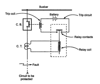
Trip Coil Of Circuit Breaker Under Repository Circuits 23149 Next Gr

130 Electrical Ideas In 2021 Diy Electrical Home Electrical Wiring Electrical Projects

Shunt Trip Breaker Wiring Diagram Explanation

Michael Lynn Walrus0910 Profile Pinterest
0 Response to "37 ge shunt trip breaker wiring diagram"
Post a Comment