36 draw the shear diagram for the compound beam which is pin connected at b.
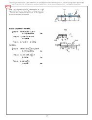
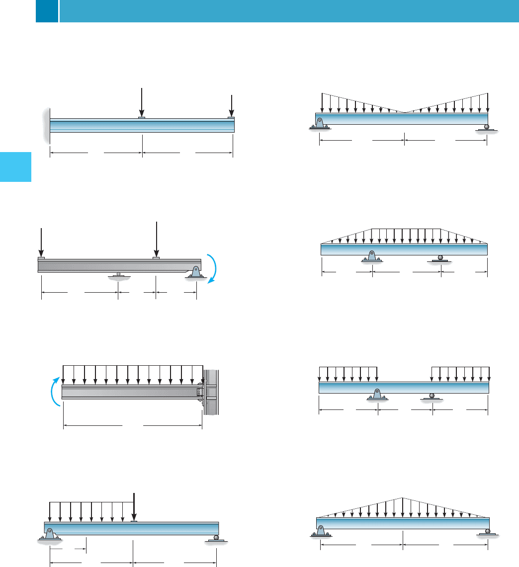
Analysis of Simple Diaphragm and Shear Wall Systems Problems ... pin-connected joint fixed support A B P actual beam L/2 L/2 torsional spring joint pin support torsional spring support idealized beam A B ... The compound beam is stable. It is also indeterminate to the second degree. Draw the shear diagram for the compound beam which is pin connected at b. 100 17 ratings or. In the frame shown determine the internal forces a in member acf at point j and in member bcd at point k. This structure is not fully stable. The beam consists of two segments pin connected at b.
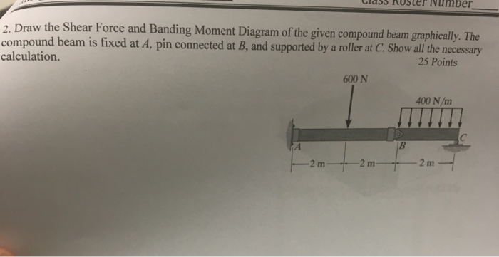
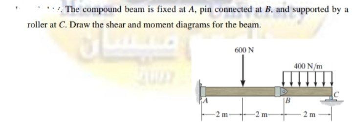
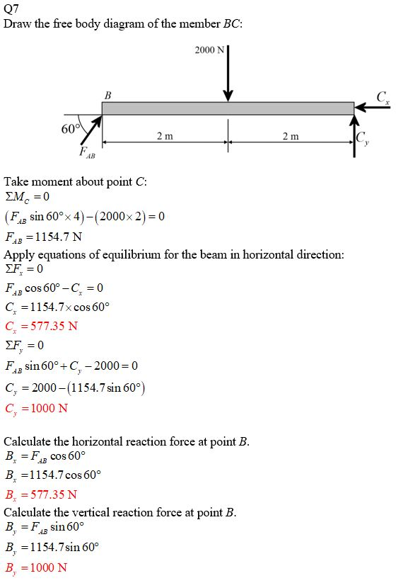
The compound beam is fixed at A, pin connected at B, and supported by a roller at C. Draw the shear diagram and the moment diagram for the beam.
Draw the shear diagram for the compound beam which is pin connected at b.
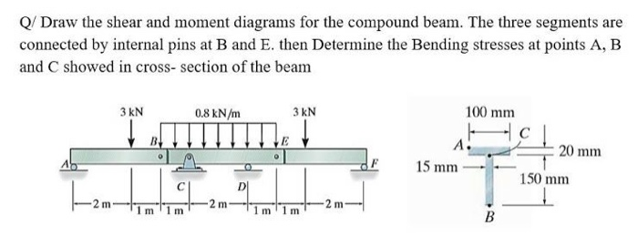
Topic: Figure 1 Part B Draw the moment diagram for the beam. The Pound Beam Is Fixed At A Connected At B And Supported A Roller At C Draw The Shear And Moment Diagrams For The Beam Holooly The Compound Beam Is Fixed At A: Content: Explanation: File Format: PDF: File size: 1.6mb: Number of Pages: 55+ pages: Publication Date: August 2020 The beam consists of three segments pin connected at B and E. Draw the shear and moment diagrams for the beam. The beam consists of three segments pin connected at B and E. Draw the shear and moment diagrams for the beam. Nov 11, 2021. SOLUTION.PDF. SOLUTION.PDF Get Answer To This Question. Drawing shear force and bending moment diagram for a compound beam#Engineering #civil_engineering #structuralengineering #structural_engineering#هندسة_مدنية#...
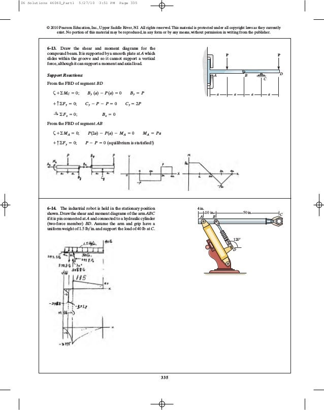
Draw the shear diagram for the compound beam which is pin connected at b.. Compound beams are structures composed of two or more elements connected by an internal connection. Think of it as two or more beams fastened together. Before proceeding, we highly recommend reading our basics guide in analysing beams as well as how to relate the load, shear, and moment for easy analysis. A short link at B is used to connect beams AB and BC to form the compound beam shown. Draw the shear and moment diagrams for the beam if the supports at A and B are considered fixed and pinned, respectively. Pin-Connected Frame. For rigid plane frames, there are three requirements for complete analysis: (1) finding the values of the reaction components, (2) modelling how the principal stresses (axial, shear, and moment) act on the structure, and (3) determining the deflected shape. An interesting feature of this problem is that we have an internal ... Mechanical Engineering. Mechanical Engineering questions and answers. The compound beam is fixed at A, pin connected at B, and supported by a roller at C. Draw the shear and moment diagrams for the beam. 800 N 500 N/m C A ІВ - 3m - 3m 3m.
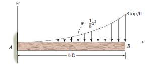
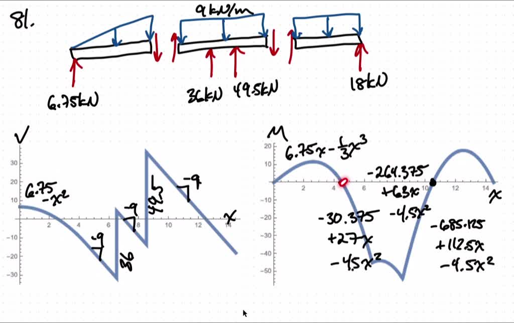
Problem 6: Bending Moment Diagram Plot shear and bending-moment diagrams for a simply supported beam with a uniformly distributed load; see Figure. Figure Solution A section at a distance x from the left support is taken as shown in figure (b). The shear is found out by subtracting the load to the left of the section from the left upward reaction. The compound beam is fixed at A, pin connected at B, and supported by a roller at C. Draw the shear and moment diagrams for the beam. 400 N/m \B -2 m- -2 m- 2 m check_circle Expert Answer Beams -SFD and BMD: Example (4) Draw the SFD and BMD for the beam Solution: Draw FBD of the entire beam and calculate support reactions using equilibrium equations Reactions at supports: 2 wL R A R B w Develop the relations between loading, shear force, and bending moment and plot the SFD and BMD ME101 - Division III Kaustubh Dasgupta 10 4.3 Shear- Moment Equations and Shear-Moment Diagrams The determination of the internal force system acting at a given section of a beam : draw a free-body diagram that expose these forces and then compute the forces using equilibrium equations. The goal of the beam analysis -determine the shear force V and
Step 1. 1 of 7. In this task, we need to draw the shear and moment diagrams for the beam. Also, we need to determine the values of the bending moment at point. B B B. . Step 2. 2 of 7. Free body diagram. The compound beam in the attachment is fixed at A, pin connected at B, and supported by a roller at C. (a) Draw the shear diagrams for the beam. (b) Draw the moment for the beam. The compound beam is fix supported at A, pin connected at B and supported by a roller at C. Draw the shear and moment diagrams for the beam. 3 ft 610 C B A 6 ft 7 Solutions 44918 1/27/09 10:39 AM Page 611 © 2010 Pearson Education, Inc., Upper Saddle River, NJ. The compound beam is fix supported at A, pin connected at B and supported by a roller at C. Draw the shear and moment diagrams for thebeam. Students also viewed these Civil Engineering questions Draw the shear and moment diagrams for beamCD.
Solved Draw The Shear And Moment Diagrams For The Compound Beam The Beam Is Pin Connected At E And F
The compound beam is fixed at A, pin connected at B, and supported by a roller at C. Draw the shear and moment diagrams for the beam. Results. See All Results. Question: Mechanics of Materials - Instructor Solutions Manual [EXP-4667]
329 6 1 Draw The Shear And Moment Diagrams For Aerostudents
A reinforced concrete pier is used to support the 60 kN 35 kN 35 kN 35 kN 60 kN stringers for a bridge deck. Draw the shear and moment 1 m 1 m 1.5 m 1.5 m 1 m 1 m diagrams for the pier when it is subjected to the stringer loads shown. Assume the columns at A and B exert only vertical reactions on the pier.

Tutorial 6a Pdf
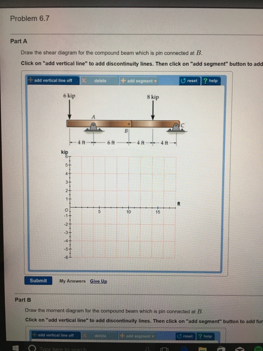
Transcribed image text: Draw the shear diagram for the compound beam which is pin connected at B. Click on "add vertical line" to add discontinuity lines. Then click on "add segment" button to add Draw the moment diagram for the compound beam which is pin connected at B. Click on "add vertical line" to add discontinuity lines.
Solved A The Compound Beam Is Fixed At A Pin Connected At B And 1 Answer Transtutors
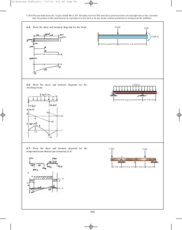
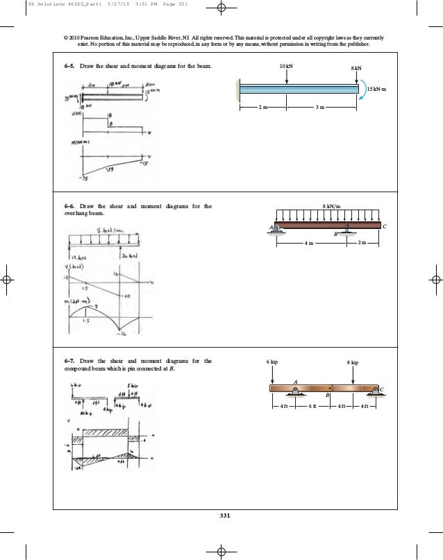
Draw the shear and moment diagrams for the beam. 2 m 3 m 10 kN 8 kN 15 kNиm 6-6. Draw the shear and moment diagrams for the overhang beam. A B C 4 m 2 m 8 kN/m 6-7. Draw the shear and moment diagrams for the compound beam which is pin connected at B. 4 ft 6 kip 8 kip A C B 6 ft 4 ft 4 ft 06 Solutions 46060_Part1 5/27/10 3:51 PM Page 331 5.

The Compound Beam In The Attachment Is Fixed At A Pin Connected At B And Supported By A Roller At C A Draw The Shear Diagrams For The Beam B Draw The
The compound beam is fixed at A, pin connected at B, and supported by a roller at C. Draw the shear and moment diagrams for the beam. Students also viewed these Sciences questions View Answer

Solved The Beam Consists Of Three Segments Pin Connected At B And E 1 Answer Transtutors
the compound beam in the attachnent is fixed at A, pin connected at B, and supported by a roller at C. part A. draw the shear diagram for the beam. part B. draw the moment for the beam. fullscreen Expand.
Solved Draw The Shear Force And Banding Moment Diagram Of The Given 1 Answer Transtutors
This is an example problem that will show you how to graphically draw a shear and moment diagram for a beam. In general the process goes like this:1) Calcul...
Solved The Compound Beam Is Fixed At A Pin Connected At B And Supported By A Roller At C Draw The Shear And Moment Diagrams For The Beam
Sketch the shear and moment diagrams for a compound beam shown. ... Draw the shear and moment diagrams for the frame shown. Assume A is a pin, C is a roller, ... that are pin connected at their ends C and supported by a pin at A and a rocker at B. Determine the maximum tension in the cable IH.
Answered The Compound Beam Is Fixed At A Pin Bartleby
F.1 (b), the positive sign convention is (a) tension axial force, (b) shear forces that produce clockwise moments and (c) bending moments that result in tension stresses in the interior frame fibers. The sign convention of F.1(b) can be seen to be equivalent to the beam sign convention rotating columns AB and CD to line up with beam BC.

Solved 7 56 Draw The Shear And Moment Diagrams For The Beam 7 57 Draw 1 Answer Transtutors
The beam shown below is supported by a pin at A and roller at B. Calculate the reactions at both supports due to the loading. 20 kN 40 kN 2 m 3 m 4 m ... Then, draw the shear force diagram (SFD) and bending moment diagram (BMD). b) If P = 20 kN and L = 6 m, draw the SFD and BMD for the beam. P kN L/2 L/2 A B EXAMPLE 4 .
Determine The Horizontal And Vertical Components Of Force Which The Pin At C Exerts On Member Bc Of The Frame In Fig 6 26a The Compound Beam Shown In Fig 6 27a Is Pin
The compound beam is fixed at a. Draw the shear diagram for the compound beam which is pin connected at b. 0 cv 400 n tef. The beam rests on a foundation that produces a uniformly distributed load over the entire length. Draw the shear and moment diagrams for the beam. The compound beam is fixed at a pin connected at b and supported by a roller ...
Hibbeler R C Structural Analysis
Drawing shear force and bending moment diagram for a compound beam#Engineering #civil_engineering #structuralengineering #structural_engineering#هندسة_مدنية#...
Solved Q Draw The Shear And Moment Diagrams For The Compound Chegg Com
The beam consists of three segments pin connected at B and E. Draw the shear and moment diagrams for the beam. The beam consists of three segments pin connected at B and E. Draw the shear and moment diagrams for the beam. Nov 11, 2021. SOLUTION.PDF. SOLUTION.PDF Get Answer To This Question.

The Compound Beam Is Fixed At A Pin Connected At B And Supported By A Roller At C Draw The Shear Diagram And The Moment Diagram For The Beam Study Com
Topic: Figure 1 Part B Draw the moment diagram for the beam. The Pound Beam Is Fixed At A Connected At B And Supported A Roller At C Draw The Shear And Moment Diagrams For The Beam Holooly The Compound Beam Is Fixed At A: Content: Explanation: File Format: PDF: File size: 1.6mb: Number of Pages: 55+ pages: Publication Date: August 2020
Ch06 07 Pure Bending Amp Transverse Shear
Solved Draw The Shear Diagram For The Compound Beam Which Is Chegg Com
Infobimbo Com
Ch06 07 Pure Bending Transverse Shear

The Compound Beam Is Fixed At A Pin Connected At B And Supported By A Roller At C Draw The Shear And Moment Diagrams For The Beam Holooly Com

Hibbeler R C Structural Analysis

Draw The Shear And Moment Diagrams For The Compound Beam Shown In Fig 4 15a Assume The Homeworklib
.PNG)
Solved The Beam Consists Of Two Segments Pin Connected At B Draw The Shear A Solutioninn

The Compound Beam Is Fixed At A Pin Connected At B And Supported By A Roller At C Draw The Shear And Moment Diagrams For The Beam Holooly Com

7 81 The Beam Consists Of Three Segments Pin Connected At B And E Draw The Shear Homeworklib
.PNG)
Solved The Compound Beam Is Pin Supported At B And Supported By Rockers At A Solutioninn

The Compound Beam Is Fixed At A Pin Connected At B And Supported By A Roller At C Draw The Shear And Moment Diagrams For The Beam Holooly Com
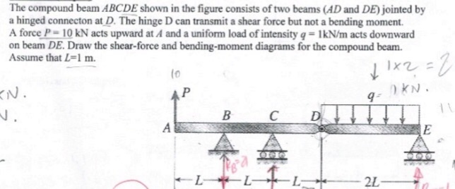
Solved The Compound Beam Abcde Shown In The Figure Consists Of Two Beams 1 Answer Transtutors
Ch06 07 Pure Bending Amp Transverse Shear
Solved Draw The Shear And Moment Diagrams For The Compound Beam The Beam Is Pin Connected At E And F
1 4 Internal Forces In Beams And Frames Engineering Libretexts
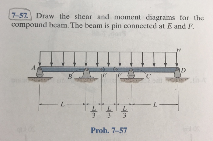
Solved 7 57 Draw The Shear And Moment Diagrams For The Chegg Com
Solved Draw The Shear And Moment Diagrams For The Compound Beam The Beam Is Pin Connected At E And F
Solved The Compound Beam Is Fixed At A Pin Connected At B And Supported By A Roller At C Draw The Shear And Moment Diagrams For The Beam

Internal Forces Compound Beam Spr18 Youtube

Hibbeler Statics 12 Ed Cap 7 2

The Compound Beam Is Fixed At A Pin Connected At B And Supported By A Roller At C Draw The Shear And Moment Diagrams For The Beam Holooly Com
0 Response to "36 draw the shear diagram for the compound beam which is pin connected at b."
Post a Comment