41 how to draw bending moment diagram
PDF CIVL 3121 Shear Force and Bending Moment Diagrams for ... Shear and Moment Diagrams for Frames Next, solve the equations of equilibrium for member CD. M C 0 Fy 0 11.84k Cy C y= 11.84 k MC= 0 Fx 0Cx Cx= 0 11.84 k 16 ft. Cy Cx MC MC Shear and Moment Diagrams for Frames Now, let's draw the shear and moment diagram (remember to draw the diagram on the compression side of the member). PDF Structural Axial, Shear and Bending Moments (Free Body Diagram) is drawn to determine the equations express- ing the shear and bending mo- ment in terms of the distance from a convenient origin. Plotting these equations produces the shear and bending moment diagrams. 7 V and M are in the opposite directions of the positive beam sign convention 8 Shear and Bending Moment Diagrams Zero Shear
Shear Force and Bending Moment Diagram for simply ... Shear Force and Bending Moment Diagram for simply supported beam version 1.0.0.0 (3.44 KB) by Sajeer Modavan This Matlab code can be used for finding Support reaction, Maximum Bending Moment, SFD and BMD

How to draw bending moment diagram
Easy Way to Draw Shear Force Diagram and Bending Moment ... This is a tutorial to make shear force diagram and bending moment diagram easily for a simply supported beam loaded with concentrated loads. the method indic... Mohr’s Circle Calculator for Plane Stress and Plane Strain ... Oct 22, 2014 · The first free, easy to use customizable Bending Moment Diagram and Shear Force Diagram Calculator for simply supported Beams Main menu. Skip to primary content. Skip to secondary content. Home; ... if we want to draw it graphically. Axial, Shear & Moment Diagrams - StructNotes There is zero bending moment at a hinge. All AFDs, SFDs, and BMDs follow these basic rules. We will refer to them as we go through the following main steps in each example: Find the support reaction forces/moments. Determine axial/shear forces. Draw axial/shear force diagrams. Determine bending moment. Draw bending moment diagram. Example 1
How to draw bending moment diagram. Learn How To Draw Shear Force And Bending Moment Diagrams ... Shear Force and Bending Moment Diagrams: This website is useful because it explains point loads and point moments. It also explains step by step equilibrium moments and forces, and it gives you a brief example of them and how to derive/draw shear forces and bending moment diagrams. Answered: Prob. 1. Draw the shear force and… | bartleby Question. Transcribed Image Text: Prob. 1. Draw the shear force and bending moment diagram due to the applied load for the given simple beam 3t 3t 3t 2 -3- -3-3- Prob. 2 For the given simple beam in Fig. 3.9, draw the normal force, shear force and bending moment diagram due to the applied load. 20 t 4 -. Bending Moment and Shear Force Diagram Calculator | The ... Bendingmomentdiagram.com is a free online calculator that generates Bending Moment Diagrams (BMD) and Shear Force Diagrams (SFD) for most simple beams. The calculator is fully customisable to suit most beams; which is a feature unavailable on most other calculators. ... The calculations are only set to draw the shear force and bending moment of ... 6.2 Shear/Moment Diagrams – Engineering Mechanics: Statics Since the function for the bending moment is parabolic, the bending moment diagram is a curve. In addition to the two principal values of bending moment at x = 0 m and at x = 5 m, the moments at other intermediate points should be determined to correctly draw the bending moment diagram. The bending moment diagram of the beam is shown in Figure ...
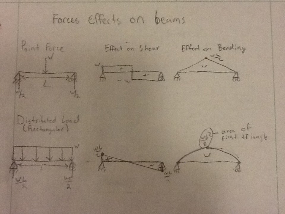
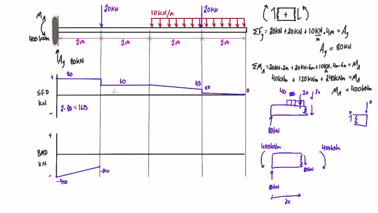
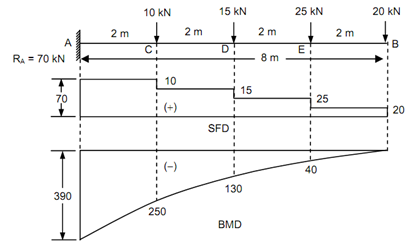
How to draw the shear-force and bending-moment diagrams ... Answer: Start with the shear force diagram. Starting from the unsupported end of the cantilever you would start with zero shear force at the point where you first encounter applied load as you move today the fixed support. The shear force will increase linearly as you continue to move toward the ... PDF 4. Bending Moment and Shear Force Diagram Bending Moment at XX is obtained by treating the load to the left of XX as a concentrated load of the same value (w.x) acting through the centre of gravity at x/2. S.F and B.M diagram Therefore, the bending moment at any cross-section XX is .2 .. x 22 x wx Mwx Therefore the variation of bending moment is according toparabolic law. How to Calculate and Draw Bending Moment and Create BMD ... BM @ E: Me = BM due to the 20KN force + BM due to the 10KN \ M UDL + BM due to the reaction force Rc. = - 20 * (1+1+1+1) - (10*2X2) + (60*2) = 0. Step-4: Plot the Bending Moments: Just now you have calculated the BM values at different points of the beam, now plot the values and you will get the bending moment diagram like below: BMD of the ... Shear Force and bending moment diagram - ExtruDesign Steps to draw Shear force and Bending moment diagrams In SFD and BMD diagrams Shear force or Bending moment represents the ordinates, and the Length of the beam represents the abscissa. Consider the left or the right portion of the section. Add the forces (including reactions) normal to the beam on the one of the portion.
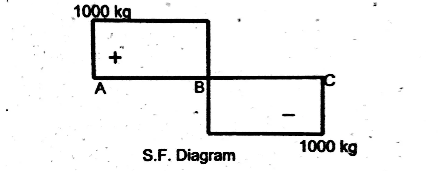
Python Code for Drawing BMD and SFD (Bending Moment and ... The code, given below, is created using Python and using Numpy and Matplotlib libraries. It can draw the bending moment diagram (BMD) and Shear Force Diagram (SFD) for a Simply Supported Beam (SSB) with a point load at any location on that beam. The solution code when run will ask for the following inputs: Bending Moment Diagram - an overview | ScienceDirect Topics Fig. 13.31 shows bending moment diagrams of the frame under vertical loads: three bending moment diagrams are provided for the cases of rigid-jointed frames, frame A, and frame B, respectively. All three frames are subjected to the same vertical load. While the magnitude of this vertical load is not important, as the analysis is elastic and it is the relative differences in bending moments ... statics - Drawing Bending Moment Diagrams - Engineering ... The fastest, most reliable way of finding the maximum bending moment, especially for simple cases, would be to use established beam design formulas such as: DA 6 - Beam Design Formulas with Shear and Moment Diagrams. If you knew where the location of maximum bending moment was, you could take a cut at that location and calculate it directly as ... How to Draw Shear Force & Bending Moment Diagram | Simply ... Draw shear force and bending moment diagram of simply supported beam carrying uniform distributed load and point loads. As shown in figure. Solution First find reactions R1 and R2 of simply supported beam. Reactions will be equal. Since, beam is symmetrical. R1 = R2 = W/2 = (600 +600 + 200 x4)/2 = 1000kg Hence, R1 = R2 = 1000 kg. Shear Force
Structural Design: Drawing Bending Moment Diagram for ...
How to Calculate and Draw Shear and Bending Moment ... These instructions will help you to calculate and draw shear and bending moment diagram, as well as draw the resulting deflection. Knowing how to calculate and draw these diagrams are important for any engineer that deals with any type of structure because it is critical to know where large amounts of loads and bending are taking place on a beam so that you can make sure …
Bending Moment Diagram - BrainDuniya
Shear And Bending Moment Diagrams For Frames ... Draw the shear and moment diagrams for the following frame: First, find as many external reactions as possible. Second, cut the frame into its component members and find the internal reactions Next, solve the equations of equilibrium for each member. Let's start with member AB. Next, solve the equations of equilibrium for member CD.

SHEAR FORCE AND BENDING MOMENT DIAGRAM FOR OVERHANGING BEAM ...
Ultimate Guide to Shear Force and Bending Moment Diagrams ... Being able to draw shear force diagrams (SFD) and bending moment diagrams (BMD) is a critical skill for any student studying statics, mechanics of materials, or structural engineering. ... Shear force and bending moment diagram example #1: single point load; Shear force and bending moment diagram example #2: multiple point loads ...
How to Draw Shear Force & Bending Moment Diagram | Simply ...
How to Draw Bending Moment & Shear Force Diagrams - Simply ... This video explains how to draw shear force diagram and bending moment diagram with easy steps for a simply supported beam loaded with a concentrated load. S...
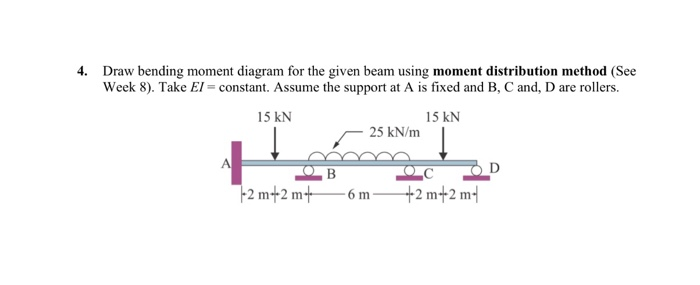
Solved: 4. Draw bending moment diagram for the given beam
1.12: Moment Distribution Method of Analysis of Structures ... Aug 03, 2021 · Draw one bending moment and one shearing force diagram for the given beam by combining the diagrams in step 9. Example 12.1 Using the moment distribution method, determine the end moments and the reactions at the supports of the beam shown in Figure 12.6a .

Solution: a draw shear force diagram sfd and bending moment ...
The Ultimate Guide to Shear and Moment Diagrams ... 💡 The internal bending moment , is the bending moment we represent in a bending moment diagram. The bending moment diagram shows how (and therefore normal stress) varies across a structure. If we know the state of longitudinal or normal stress due to bending at a given section in a structure we can work out the corresponding bending moment.

Drawing Shear Force, Bending Moment Diagram » File Exchange ...
Drawing Bending Moment Diagrams Effectively - MD - Engineering First, you need to calculate the left side bending moment situation of the singular force, by placing 'x' to the left side of the singular shear force. Then calculate the bending moment at that point, from the left side of the point. Then place the 'x' on the right side, make your calculation again. For Uniformly Distributed Shear Forces
Mechanics of Materials Chapter 4 Shear and Moment In Beams
PDF A Practical Graphical Approach for Drawing Shear Force and ... The ability to draw shear force and bending moment diagrams on beam-like components is an important skill for mechanical engineering students. We found that some students had difficulty to draw effectively the shear force and bending moment diagrams during the course and even in their senior year. Although the method of sections can produce all ...

Drawing Shear Force, Bending Moment Diagram » File Exchange ...
a) Draw the bending moment (M) diagram due to t = +20 ... Civil Engineering questions and answers. a) Draw the bending moment (M) diagram due to t = +20 C uniform temperature change. b) Draw the bending moment (M) diagram due to ∆t = +15 C relative temperature change. c) Draw the bending moment (M) diagram due to the prescribed support settlements (EI = 1.800.000 kNm2 , ε = 10^ (−5) 1/ C).

Moment Diagrams Constructed by the Method of Superposition ...
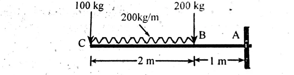
[Solved] a) Draw shear force diagram and bending moment ... a) Draw shear force diagram and bending moment diagram of the beam. b) Calculate deformation of the beam and deflection at both ends of beam (where the 100kg loads are) Please dont leave answer incomplete :) Thank you. Image transcription text. 20kg 1310.mm 100kg 100kg - 445mm - -445mm- VVV V V 420mm 415mm HAND A. HAND B 30mm 3cm 2200mm 2.2 M...
The Ultimate Guide to Shear and Moment Diagrams ...
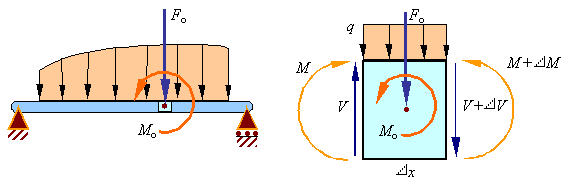
Lecture 2 - Shear and Bending Moment and Review of Stress 3.2 - Shear Force & Bending Moment Diagrams What if we sectioned the beam and exposed internal forces and moments. This exposes the internal Normal Force Shear Force Bending Moment ! What if we performed many section at ifferent values Of x, we will be able to plot the internal forces and bending moments, N(x), V(x), M(x) as a function Of position!
1.4: Internal Forces in Beams and Frames - Engineering LibreTexts
How To Draw Bending Moment Diagram For Continuous Beam ... How to draw shear force bending moment diagram simply supported beam exles ering intro solved determine the reactions and draw shear bending moment 1 transtutors problem 853 continuous beams with fixed ends strength of materials review at mathalino solved yze the continuous beam shown in figure below using moment distribution method draw shear ...
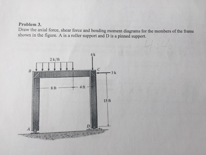
Solved) - Draw the axial force, shear force and bending ...
How To Find The Maximum Bending Moment In A Beam - New ... Feb 29, 2020 · Solved determine the maximum bending moment for beam please 1 and 2 with plete solution exercise beam flexure for the cantilever homeworklib shear force and bending moment materials ering reference with worked exles problem 6 58 the beam is made from three boards nailed together as shown if moment acting on cross section m 1 kip ft determine ...
How to Draw Shear Force & Bending Moment of Cantilever With ...
How to Calculate Bending Moment Diagram? | SkyCiv Finally calculating the moments can be done in the following steps: 2. From left to right, make "cuts" before and after each reaction/load To calculate the bending moment of a beam, we must work in the same way we did for the Shear Force Diagram. Starting at x = 0 we will move across the beam and calculate the bending moment at each point. Cut 1

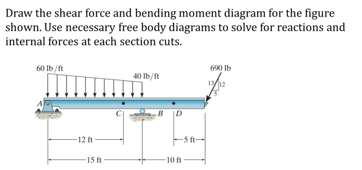
Draw the shear force and bending moment diagrams for the beam ...
How to Draw Moment Diagrams | ReviewCivilPE Put a dot at the end point ( 8.35 lbft) and draw a straight line to it ( this shear segment is also constant). The area for region 3 is 8.35 lb*ft and the shear is constant resulting in a linear moment. The moment at the end of this segment is 16.35 ft*lb. Region 4 is different from the others, it's a triangle instead of a rectangle.
How can draw bending moment diagram directly from loading of ...
HW 19 SOLUTIONS - University of Utah 6—25. Draw the shear and moment diagrams for the beam- The two segments are joined together at B. 8 kip 3 kip,ft 5 ft *6—20. Draw the shear and moment diagrams for the beam, and determine the shear and moment throughout the beam 10 kip 2 kip/ft g Kip 8 kip 40 kip.ft as functions of x. Support Reactions: As shown on FBD. Shear and Moment ...
Solved Draw the shear force and bending moment diagrams for ...
Axial, Shear & Moment Diagrams - StructNotes There is zero bending moment at a hinge. All AFDs, SFDs, and BMDs follow these basic rules. We will refer to them as we go through the following main steps in each example: Find the support reaction forces/moments. Determine axial/shear forces. Draw axial/shear force diagrams. Determine bending moment. Draw bending moment diagram. Example 1

Learn How To Draw Shear Force And Bending Moment Diagrams ...
Mohr’s Circle Calculator for Plane Stress and Plane Strain ... Oct 22, 2014 · The first free, easy to use customizable Bending Moment Diagram and Shear Force Diagram Calculator for simply supported Beams Main menu. Skip to primary content. Skip to secondary content. Home; ... if we want to draw it graphically.

Bending Moment Diagram - an overview | ScienceDirect Topics
Easy Way to Draw Shear Force Diagram and Bending Moment ... This is a tutorial to make shear force diagram and bending moment diagram easily for a simply supported beam loaded with concentrated loads. the method indic...

How to Draw Bending Moment and Shear Force Diagrams Without Equations - Example 2
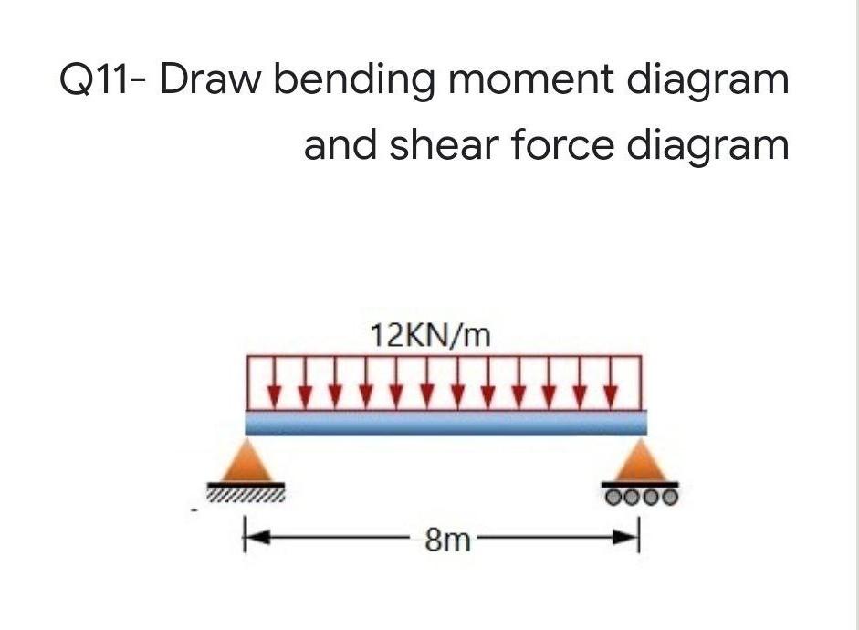
Solved Q11- Draw bending moment diagram and shear force ...
Shear Load and Bending Moment Diagrams
Solved Draw the shear force and bending moment diagram for ...
Solved Draw the shear force and bending moment diagram of ...

structural engineering - How to plot bending moment diagram ...

Shear Force and Bending Moment Diagrams - Wikiversity
Answered: 3. Draw the shear and bending-moment… | bartleby

Draw the shear force and bending moment diagrams for the beam ...

Shear Force and Bending Moment Diagrams - Wikiversity
How to Calculate and Draw Shear and Bending Moment Diagrams ...
6.2 Shear/Moment Diagrams – Engineering Mechanics: Statics
How To Draw Shear Force And Bending Moment Diagram In Case Of ...
Shear force and bending moment diagram practice problem #4

Draw the shear and bending moment diagrams and the ...
Solved] Draw the shear and bending-moment diagrams for the ...

Drawing Shear and Moment Diagrams for Beam
Draw the bending moment diagram and shear force diagram ...
Shear And Bending Moment Diagrams For Frames - Construction How

Drawing Bending Moment Diagrams Effectively - MD - Engineering

How to Calculate and Draw Shear and Bending Moment Diagrams ...
Solved Draw Shear Force and Bending Moment Diagram for the ...
0 Response to "41 how to draw bending moment diagram"
Post a Comment